 Open Access Article
Preparation and catalytic performance of active metal sintered membrane reactor anchored with Pt atoms
Xiaoliang Ren,
Shufang Wang *,
Xiaoshu Ding,
Dongsheng Zhang* and
Yanji Wang
 *
*
Hebei Provincial Key Lab of Green Chemical Technology and High Efficient Energy Saving, School of Chemical Engineering and Technology, Hebei University of Technology, Tianjin 300130, China. E-mail: wangshufang@hebut.edu.cn; zds1301@hebut.edu.cn; yjwang@hebut.edu.cn
First published on 13th January 2021
Abstract
In the chemical industry, reactors are typically designed and filled with supported catalyst particles. However, the intrinsic problems associated with the internal/external diffusion effect and catalyst separation/loss in these traditional reactors can be very challenging to mitigate. To address these issues, herein, an active metal sintered membrane reactor anchored with Pt atoms was successfully developed, and applied into continuous, liquid-phase, hydrogenation processes. The catalyzing reactions transpired on the active sites that were fastened onto the surface of the reactor's microchannels. As a result, the mass transfer at the gas–liquid–solid three-phase was greatly enhanced, and an incredibly high reaction efficiency was obtained. The novel, active reactor demonstrated a superior catalytic performance and stability to nitrobenzene (NB) hydrogenation at 120 °C and 0.5 MPa H2, which enabled an aniline (ANI) yield of 19.28 molANI h−1 L−1. This work opens a new window for the design of high-performance gas–liquid–solid reactor toward multiphase catalytic reactions.
Introduction
Multi-phase catalytic reactions, such as oxidation, hydrogenation, carbonylation, etc., are industrially crucial to many processes in the chemical field.1–6 The chemical processes typically involve gas and liquid reactants in the presence of a solid catalyst.7–11 For instance, fixed bed reactors (e.g. trickle-bed reactor, bubble column reactor) and stirred tank slurry reactors are usually employed for gas–liquid–solid, three-phase reaction systems.12–16 However, these traditional reactors possess a few intrinsic problems: (i) the diffusion of reactants and/or products is hindered by limited diffusion channels within the catalytic zone, which result in decreased reaction rates and poor product selectivity.17–20 (ii) poor thermal conductivity and mechanical strength in catalyst supports can lead to catalyst sintering and structural degradation during these reactions.21–23 (iii) the post-reaction, separation of the catalyst from the products increases the operational cost.24To address these issues, in our preliminary work,25 Pt-metal catalysts were successfully prepared by creating single-atom active sites on the surface of metallic catalyst supports. Due to the smooth metal surface and lack of micropores, the diffusion and mass-transfer limitations of the reactants on the catalyst surface were effectively reduced. By the foregoing method, catalytic active components were fastened onto the surface of metal internals (e.g. inner walls, stirring impeller, etc.) in a kettle reactor, resulting in an active kettle reactor with superior hydrogenation performance. Thus, the challenges of limited internal diffusion, poor catalyst separation and loss, were mitigated. It was found that the hydrogenation activity of the aforementioned reactor predominantly depends on the surface area of metal internals. Unfortunately, it is rather difficult to further improve the effective surface area of kettle reactor. If the reactor vessel was enlarged, the active surface area per unit reactor volume would significantly decrease, which lead to a diminished production efficiency. Furthermore, the reaction process was greatly affected by the mass transfer (external diffusion) of gas–liquid–solid three-phase in kettle reactor. In order to obtain a good mass transfer effect, vigorously stirring speed was required. But it is very difficult to achieve in large-scale industrial reactor.
Recently, metal sintered membrane was applied in the field of filtration and mixing.26–28 It retains the superior characteristics of metal substrates, while possessing abundant microchannel architectures, large surface areas for gas–liquid contact, and great mass-transfer rates.29,30 Considering the advantage of the metal sintered membrane, active Pt component was loaded into the microchannels of the metal sintered membrane, and the gas–liquid–solid catalytic reaction could transpire within the microchannels. It is anticipated that incorporation of active metal sintered membrane into the reactor will not only provide a large active surface area, but also enhance the mass transfer process, both of which could promote the multi-phase catalytic reaction. As far as we concerned, few works have been reported on loading Pt into metal sintered membranes for continuous gas–liquid–solid catalytic reaction.
Herein, a novel, active metal sintered membrane reactor anchored with Pt atoms was prepared. The performance of the active membrane reactor was assessed by continuous hydrogenation of nitro-compounds to anilines reaction. Various operating parameters were also investigated in the active membrane reactor.
Experimental methods
Materials
In this study, all chemicals were of analytical grade and used without further purification. Chloroplatinic acid hexahydrate and 2,4-dinitrotoluene were supplied from Sinopharm Chemical Reagent Co., Ltd. Nitrobenzene was purchased from Tianjin Fuchen Chemical Reagent Co., Ltd. o-Nitrotoluene, m-nitrotoluene and p-nitrotoluene were purchased from Shanghai Aladdin Reagent Co., Ltd. 4-Nitroanisole was supplied by TCI (Shanghai) Chemical Industry Development Co., Ltd. Ethanol was supplied by Tianjin Chemical Reagent Third Factory. The water used was distilled water obtained from an Ulupure UPR-II system.Preparation of active membrane reactor
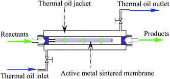
A tubular 316 L stainless steel sintered membrane (9 mm inner diameter, 11 mm outer diameter, 32 cm length, 30% porosity and 50 μm average pore size) was selected to prepare active membrane reactor. The metal sintered membrane was continuously treated with chloroplatinic acid aqueous solution of 0.80 ppm Pt concentration for 4 h under 155 °C and 0.45 Mpa H2. After that, the metal membrane was cleaned with deionized water, and naturally dried at room temperature. Then, an active metal sintered membrane anchored with Pt atoms was obtained, and used for fabricating the active membrane reactor. The configuration of the active metal sintered membrane reactor is depicted in Fig. 1.Characterizations
Scanning Electron Microscopic (SEM) image was recorded on a FEI Nano SEM450 microscope. The distribution of Pt active component was analyzed using energy-dispersive X-ray spectroscopy (EDS, Ametek Octane Plus). The XPS measurement was performed on Escalab 250Xi (Thermo Fisher Scientific, USA) using Al Kα radiation as the X-ray source. The C 1s peak at 284.8 eV, representing carbon contamination, was used as the reference for the spectra. Inductively coupled plasma atomic emission spectrometry (ICP-AES) analysis was performed on a PerkinElmer Optima 7300 V instrument.Performance evaluation
The reaction performance of the as-prepared membrane reactor was evaluated via the continuous, liquid-phase hydrogenation of nitroaromatic compounds into their corresponding anilines as the chosen model-reaction. Initially, both the gas and liquid enter the reactor through the inner cylinder of the tubular membrane, then radially proceed out through the microchannels of the membrane and along the exterior of the membrane (between the concurrent cylinders) until the products leave the reactor. Meanwhile, the heat generated in the reaction process was dissipated into the thermal oil flowing in the jacket.For comparison, an active trickle-bed reactor filled with metal θ-ring packing was prepared by the same method as active membrane reactor, enabling the hydrogenation of nitrobenzene (NB) to aniline (ANI). The inner tube diameter of the trickle-bed reactor is 18 mm, and 60 cm in length. The size of 316 L stainless steel θ-ring packing is 2 × 2 mm, with specific surface area of 3.7 m2 L−1. The loading capacity of θ-ring packing is 75 mL. During the hydrogenation process, the liquid phase was fed from the top of the reactor, while the gas was introduced at the bottom of the reactor, allowing the gas and liquid phases to flow concurrently in the trickle-bed reactor.
Lastly, the reaction products were quantitatively analyzed with a GC-2010plus (Shimadzu) gas chromatograph fitted with an FID detector.
Results and discussion
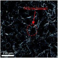
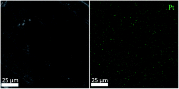
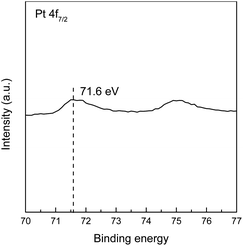
The SEM image of the active metal sintered membrane was displayed in Fig. 2. Abundant microchannel architectures could be clearly observed, the pore size was around 50 μm, such vigorously microchannel structure was able to induce the perturbation to the fluid flow.31 Moreover, the energy-dispersive X-ray spectroscopy (EDS) analysis of active metal sintered membrane (Fig. 3) confirmed the uniformly distribution of Pt active component on the metal membrane support. Additionally, our previous characterization result (HAADF-STEM) showed that Pt interacted on metal support was dispersed as single atoms.25 Therefore, it can be inferred that similar single atom was formed, when Pt was anchored on the metal sintered membrane support with the same way.The chemical state of Pt on the active metal sintered membrane was investigated by high-resolution XPS. The Pt 4f spectrum showed that Pt 4f7/2 located at 71.6 eV (Fig. 4). As compared to Pt0 of 71.1 eV,32 a positive shift in Pt binding energies of the active metal sintered membrane was observed. This result is consistent with our previous characterization result of Pt-metal catalyst prepared by the same method.25 Part of electrons of Pt was transferred to the carrier because of the strong interaction between Pt atoms and substrate. Thus positively charged Pt atoms were formed, and a positive shift in Pt binding energies was observed. Similar phenomena have been reported in literatures.33–36
Prior to the evaluation of the active membrane reactor, the blank test was conducted to check the activity of the bare metal sintered membrane (without loading Pt). It was found that no ANI was produced on the bare metal membrane. While in the active metal membrane reactor (loading Pt), the yield of ANI per unit membrane volume reached 19.28 molANI h−1 L−1 (see Table 1). This is consistent with characterization results (EDS and XPS) that active Pt component has been anchored on the metal sintered membrane after treated with chloroplatinic acid aqueous solution. Compared with the result of 1.04 molANI h−1 L−1 in conventional trickle-bed reactor with commercial 0.3% Pd/Al2O3 catalyst at similar reaction conditions,37 such high production efficiency of the membrane reactor brings great competitive advantage to the reactor in industrial application.
| Type of reactors | Liquid feed rate (mL min−1) | Gas feed rate (mL min−1) | Reaction temperature (°C) | H2 pressure (MPa) | ANI yield per unit membrane (packing) volume (molANI h−1 L−1) | Standard deviation | ANI yield per unit active surface area (molANI h−1 m−2) | Standard deviation |
|---|---|---|---|---|---|---|---|---|
| a Reaction conditions: 1.05 mol L−1 NB, ethanol as solvent. | ||||||||
| Active membrane reactor | 4 | 1700 | 120 | 0.5 | 19.28 | 0.460 | 0.80 | 0.019 |
| 5 | 1700 | 120 | 0.5 | 19.77 | 0.484 | 0.82 | 0.020 | |
| 6 | 1700 | 120 | 0.5 | 19.95 | 0.357 | 0.83 | 0.015 | |
| 4 | 2200 | 120 | 0.5 | 19.52 | 0.240 | 0.81 | 0.010 | |
| 4 | 1200 | 120 | 0.5 | 18.80 | 0.331 | 0.78 | 0.014 | |
| 4 | 1700 | 130 | 0.5 | 23.41 | 0.318 | 0.98 | 0.013 | |
| 4 | 1700 | 110 | 0.5 | 14.29 | 0.434 | 0.60 | 0.018 | |
| 4 | 1700 | 100 | 0.5 | 11.64 | 0.305 | 0.49 | 0.013 | |
| 4 | 1700 | 120 | 0.6 | 21.99 | 0.350 | 0.92 | 0.015 | |
| 4 | 1700 | 120 | 0.4 | 16.13 | 0.285 | 0.67 | 0.012 | |
| 4 | 1700 | 120 | 0.3 | 13.23 | 0.405 | 0.55 | 0.017 | |
| Active trickle-bed reactor | 4 | 1700 | 120 | 0.5 | 0.74 | 0.016 | 0.20 | 0.004 |
| 5 | 1700 | 120 | 0.5 | 0.89 | 0.028 | 0.24 | 0.008 | |
| 6 | 1700 | 120 | 0.5 | 1.01 | 0.030 | 0.27 | 0.008 | |
| 4 | 2200 | 120 | 0.5 | 0.81 | 0.034 | 0.22 | 0.009 | |
| 4 | 1200 | 120 | 0.5 | 0.63 | 0.018 | 0.17 | 0.005 | |
The effects of reaction temperature and H2 partial pressure on the catalytic activity of the membrane reactor were studied.
Table 1 shows the reaction results of NB hydrogenation on the membrane reactor at the H2 partial pressure of 0.3–0.6 MPa, the yield of ANI was ranged from 13.23 molANI h−1 L−1 to 21.99 molANI h−1 L−1. When increasing the reaction temperature from 100 °C to 130 °C, the ANI yield for the reactor was increased from 11.64 molANI h−1 L−1 to 23.41 molANI h−1 L−1. These results demonstrated that the reaction performance of the membrane reactor could be significantly improved by increasing reaction temperature and H2 pressure.
Moreover, the feed rates of the liquid and gas streams in the active membrane reactor were also investigated. As shown in Table 1, when changing the gas feed rates from 1200 mL min−1 to 2200 mL min−1, the ANI yield was changed from 18.80 molANI h−1 L−1 to 19.52 molANI h−1 L−1, which is a 3.83% yield increase. With increasing the liquid feed rates from 4 mL min−1 to 6 mL min−1, the yield of ANI was increased from 19.28 molANI h−1 L−1 to 19.95 molANI h−1 L−1. There is an increase of 3.48% ANI yield. These variations were not significant. The results indicated that the active membrane reactor possessed a superior multi-phase mixing and dispersion capacity. And interphase mass transfer was less influenced by the gas and liquid feed rates.
Another effective method to increase the active surface area per unit volume, is to attach the active Pt component to high surface-area metallic packing, then fill the active packing into reaction tube to prepare active trickle-bed reactor. The reaction performance of the trickle-bed reactor in NB hydrogenation was investigated, compared with that of membrane reactor at similar conditions. As can be seen from Table 1, when the liquid feed rates was changed from 4 mL min−1 to 6 mL min−1, the yield of ANI was increased from 0.74 molANI h−1 L−1 to 1.01 molANI h−1 L−1, which is a 36.5% yield increase. As the increasing of gas feed rates from 1200 mL min−1 to 2200 mL min−1, the ANI yield was varied from 0.63 molANI h−1 L−1 to 0.81 molANI h−1 L−1 (28.6% yield increase). These results showed that the reaction performance of the trickle-bed reactor was greatly affected by feed rates. The highest ANI yield per unit volume in the trickle-bed reactor was only 1.01 molANI h−1 L−1. The reaction performance of the membrane reactor (19.95 molANI h−1 L−1) was about 20 times as high as that of trickle-bed reactor. Hence the membrane reactor exhibited much higher production efficiency.
Furthermore, the reaction results per unit active surface area of the two reactors were given to compare the gas–liquid–solid mass transfer in the two reactors. It can be seen from Table 1 that the ANI yield per unit active surface area of membrane reactor was more than 3 times greater than that of the trickle-bed reactor under the same reaction conditions. And the influence of feed rates on the results of membrane reactor was obviously smaller than that of trickle-bed reactor, which demonstrated a superior mass transfer capacity of the membrane reactor. In fact, metal sintered membrane reactor possesses the characteristic of abundant microchannel architecture. And the mass transfer of gas–liquid–solid three-phase can transpire within the microchannels during the reaction. As a result, the diffusion distance from the reactants to the catalyst surface can be significantly shortened within the microscale range.38,39 Furthermore, microchannel structure is able to induce the perturbation to the fluid flow and enhance the mixing process.31,40 During the process, each individual microchannel can operate as a microreactor for carrying out the gas–liquid–solid catalytic reaction. It has been proved that continuous flow microreactor is beneficial for accelerating the reaction rate with enhanced mass transfer, as comparing to conventional reactors.31,41–43 Therefore, it was concluded that the active membrane reactor has a remarkable effect on enhancing gas–liquid–solid mass transfer and promoting the multi-phase catalytic reaction process. It was also a key factor for high production efficiency of the active membrane reactor.
A series of substituted nitroarenes were also assessed in the active membrane reactor to verify its substrate tolerance. As can be seen from Table 2, the membrane reactor exhibited a superior catalytic performance in reducing substituted nitrobenzenes (in para, meta and ortho positions) to their corresponding amines, demonstrating that the reactor's surface active sites possess good space-steric hindrance tolerance. In addition, the active membrane reactor was successfully applied to the hydrogenation of 2,4-dinitrotoluene (2,4-DNT) to 2,4-toluenediamine (2,4-TDA). Besides main product of 2,4-TDA, a small amount of by-products such as 2-nitro-4-aminotoluene and 2-amino-4-nitrotoluene, were also detected in reaction solution. The reason may be as follows. The 2,4-DNT contains two –NO2 groups, one of the –NO2 was first converted to –NH2 during the hydrogenation.44,45 The electron-donating effect of the formed –NH2 reduced the hydrogenation rate of the other –NO2 group.46,47 Thus, some by-products of mono-nitro group reduction were formed. At 0.5 MPa H2 and 120 °C, the 2,4-TDA yield per unit membrane volume reached up to 4.34 mol2,4-TDA h−1 L−1, and the reaction efficiency of the active membrane reactor was superior to that found in literature, which utilizes the traditional trickle-bed reactor equipped with 5% Pd/Al2O3 catalyst.44
| Substrate | Concentration (mol L−1) | Product yield per unit membrane volume (mol h−1 L−1) | Standard deviation | Product yield per unit active surface area (mol h−1 m−2) | Standard deviation | Product |
|---|---|---|---|---|---|---|
| a Reaction conditions: liquid flow rate: 4 mL min−1, gas flow rate: 1700 mL min−1, T = 120 °C, P = 0.50 MPa H2, ethanol as solvent. | ||||||
 |
0.22 | 4.98 | 0.100 | 0.21 | 0.004 |  |
 |
0.22 | 4.34 | 0.090 | 0.18 | 0.004 |  |
 |
0.39 | 8.33 | 0.206 | 0.35 | 0.009 |  |
 |
0.77 | 16.25 | 0.409 | 0.68 | 0.017 |  |
 |
0.77 | 15.34 | 0.289 | 0.64 | 0.012 |  |
 |
0.77 | 14.06 | 0.316 | 0.59 | 0.013 |  |
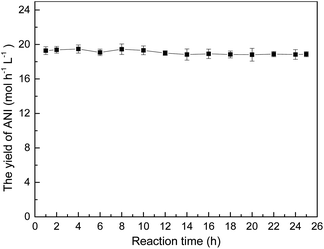
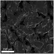
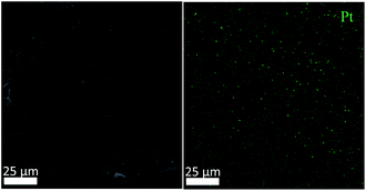
The stability of the metal sintered membrane was further evaluated in NB hydrogenation. Fig. 5 depicts the yield of ANI with respect to the operational time at 120 °C and 0.5 MPa H2. The yield of ANI consistently remained at about 19.28 molANI h−1 L−1 with minor variations during the 25 h operational period. Compared the micromorphology of the membrane before (Fig. 2) and after (Fig. 6) the long-term tests, it was found that no obvious change of the metal sintered membrane was observed, which indicated the good structure stability of the membrane reactor. The EDS analysis (Fig. 7) of active metal sintered membrane after 25 h of hydrogenation showed that the Pt atoms were still evenly distributed on the metal membrane support. Moreover, ICP-AES analysis of the reaction solution after the hydrogenation was performed, and no Pt species were detected in the solution. These results confirmed the excellent stability of the catalytic membrane reactor under normal operating conditions.
Conclusions
In this study, an active metal sintered membrane reactor anchored with Pt atoms was successfully developed, and applied to continuous liquid-phase catalytic hydrogenation processes. More specifically, the hydrogenation was carried out in the reactor's microchannels that loaded with active Pt component. Such design could not only provide large active surface area, but also enhance mass transfer process, thus improving the production efficiency. The active membrane reactor exhibited an excellent catalytic performance in the hydrogenation of NB to ANI. For instance, at 120 °C and a hydrogen pressure of 0.5 MPa, the yield of ANI per unit membrane volume reached 19.28 molANI h−1 L−1 while maintaining an impressive catalytic stability. Alternatively, hydrogenation of 2,4-DNT to 2,4-TDA can also be performed in the active membrane reactor, yielding up to 4.34 mol2,4-TDA h−1 L−1. This successful development of the novel active metal sintered membrane reactor is of great importance towards enhancing the mass transfer effect, simplifying production processes and improving production efficiency for gas–liquid–solid, three-phase reactors.Conflicts of interest
There are no conflicts to declare.Acknowledgements
This work was financially supported by the National Natural Science Foundation of China (No. 21576069, 21236001, 21606070 and 21878069) and Hebei Science and Technology Project (17214203D).References
- D. D. Falcone, J. H. Hack and R. J. Davis, ChemCatChem, 2016, 8, 1074–1083 CrossRef CAS
.
- M. Enneiymy, P. Fioux, C. Le Drian, C. M. Ghimbeu and J. M. Becht, RSC Adv., 2020, 10, 36741–36750 RSC
.
- M. Papp and R. Skoda-Foldes, J. Mol. Catal. A: Chem., 2013, 378, 193–199 CrossRef CAS
.
- B. Q. Niu, F. Lu, H. Y. Zhang, Y. C. Zhang and J. Q. Zhao, Chem. Lett., 2017, 46, 330–333 CrossRef CAS
.
- T. Sasaki, F. Devred, P. Etoy, E. M. Gaigneaux, T. Hara, S. Shimazu and N. Ichikuni, Bull. Chem. Soc. Jpn., 2019, 92, 840–846 CrossRef CAS
.
- L. B. Belykh, N. I. Skripov, T. P. Sterenchuk and F. K. Schmidt, Catal. Commun., 2020, 146, 106124 CrossRef CAS
.
- S. Chornaja, E. Sile, R. Drunka, J. Grabis, D. Jankovica, J. Kunakovs, K. Dubencovs, S. Zhizhkuna and V. Serga, React. Kinet., Mech. Catal., 2016, 119, 569–584 CrossRef CAS
.
- F. Li, B. Cao, W. X. Zhu, H. Song, K. L. Wang and C. Q. Li, Catalysts, 2017, 7, 145 CrossRef
.
- P. P. Zhang, Y. B. Hu, B. H. Li, Q. J. Zhang, C. Zhou, H. B. Yu, X. J. Zhang, L. Chen, B. Eichhorn and S. H. Zhou, ACS Catal., 2015, 5, 1335–1343 CrossRef CAS
.
- W. Y. Hao, J. C. Sha, S. R. Sheng and M. Z. Cai, Catal. Commun., 2008, 10, 257–260 CrossRef CAS
.
- W. J. Yu, L. L. Lou, K. Yu, S. S. Li, Y. Shi and S. X. Liu, RSC Adv., 2016, 6, 52500–52508 RSC
.
- L. Ding, W. Y. Yang, L. F. Chen, H. Y. Cheng and Z. W. Qi, Catal. Today, 2020, 347, 39–47 CrossRef CAS
.
- U. Herrmann and G. Emig, Ind. Eng. Chem. Res., 1998, 37, 759–769 CrossRef CAS
.
- C. Shan, Y. Xu, M. Hua, M. Gu, Z. C. Yang, P. Wang, Z. D. Lu, W. M. Zhang and B. C. Pan, Chem. Eng. J., 2018, 338, 261–270 CrossRef CAS
.
- K. Hengst, D. A. J. M. Ligthart, D. E. Doronkin, K. M. Walter, W. Kleist, E. J. M. Hensen and J. D. Grunwaldt, Ind. Eng. Chem. Res., 2017, 56, 2680–2689 CrossRef CAS
.
- M. I. McAllister, C. Boulho, L. McMillan, L. F. Gilpin, C. Brennan and D. Lennon, RSC Adv., 2019, 9, 26116–26125 RSC
.
- N. Dechamp, A. Gamez, A. Perrard and P. Gallezot, Catal. Today, 1995, 24, 29–34 CrossRef CAS
.
- S. Lee, Z. Y. Yu, N. Zaborenko and A. Varma, Chem. Eng. J., 2016, 288, 711–723 CrossRef CAS
.
- A. Zamaniyan, Y. Mortazavi, A. A. Khodadadi and A. N. Pour, J. Energy Chem., 2013, 22, 795–803 CrossRef CAS
.
- J. Aumo, J. Warna, T. Salmi and D. Y. Murzin, Chem. Eng. Sci., 2006, 61, 814–822 CrossRef CAS
.
- P. Forzatti and L. Lietti, Catal. Today, 1999, 52, 165–181 CrossRef CAS
.
- C. H. Bartholomew, Appl. Catal., A, 2001, 212, 17–60 CrossRef CAS
.
- R. Zhao, J. G. Goodwin and R. Oukaci, Appl. Catal., A, 1999, 189, 99–116 CrossRef CAS
.
- H. Q. Yang, T. Zhou and W. J. Zhang, Angew. Chem., Int. Ed., 2013, 52, 7455–7459 CrossRef CAS
.
- X. L. Ren, J. D. Li, S. F. Wang, D. S. Zhang and Y. J. Wang, Catal. Commun., 2019, 128, 105709 CrossRef CAS
.
- B. Zhu, M. Duke, L. F. Dumee, A. Merenda, E. des Ligneris, L. X. Kong, P. D. Hodgson and S. Gray, Membranes, 2018, 8, 83 CrossRef
.
- Z. Xu and J. Yu, Chem. Eng. Sci., 2008, 63, 1941–1949 CrossRef CAS
.
- H. Singh, P. Saxena and Y. M. Puri, Mater. Lett., 2020, 269, 127557 CrossRef CAS
.
- E. Reichelt, M. P. Heddrich, M. Jahn and A. Michaelis, Appl. Catal., A, 2014, 476, 78–90 CrossRef CAS
.
- J. H. Qin, Q. Chen, C. Y. Yang and Y. Huang, J. Alloys Compd., 2016, 654, 39–44 CrossRef CAS
.
- G. Chen, X. Zhu, R. Chen, Q. Liao, D. D. Ye, H. Feng, J. Liu and M. Liu, Chem. Eng. J., 2018, 334, 1897–1904 CrossRef CAS
.
- X. W. Hong and Y. Sun, Catal. Lett., 2016, 146, 2001–2008 CrossRef CAS
.
- Y. H. Qin, Y. F. Li, R. L. Lv, T. L. Wang, W. G. Wang and C. W. Wang, J. Power Sources, 2015, 278, 639–644 CrossRef CAS
.
- J. Q. Zhang, Y. F. Zhao, X. Guo, C. Chen, C. L. Dong, R. S. Liu, C. P. Han, Y. D. Li, Y. Gogotsi and G. X. Wang, Nat. Catal., 2018, 1, 985–992 CrossRef CAS
.
- B. T. Qiao, A. Q. Wang, X. F. Yang, L. F. Allard, Z. Jiang, Y. T. Cui, J. Y. Liu, J. Li and T. Zhang, Nat. Chem., 2011, 3, 634–641 CrossRef CAS
.
- L. H. Zhang, L. L. Han, H. X. Liu, X. J. Liu and J. Luo, Angew. Chem., Int. Ed., 2017, 56, 13694–13698 CrossRef CAS
.
- C. S. Couto, L. M. Madeira, C. P. Nunes and P. Araujo, Ind. Eng. Chem. Res., 2017, 56, 3231–3242 CrossRef CAS
.
- H. Lowe and W. Ehrfeld, Electrochim. Acta, 1999, 44, 3679–3689 CrossRef CAS
.
- L. Kiwi-Minsker and A. Renken, Catal. Today, 2005, 110, 2–14 CrossRef CAS
.
- C. Hutter, C. Allemann, S. Kuhn and P. Rudolf von Rohr, Chem. Eng. Sci., 2010, 65, 3169–3178 CrossRef CAS
.
- J. Kobayashi, Y. Mori, K. Okamoto, R. Akiyama, M. Ueno, T. Kitamori and S. Kobayashi, Science, 2004, 304, 1305–1308 CrossRef CAS
.
- Z. He and T. F. Jamison, Angew. Chem., Int. Ed., 2014, 53, 3353–3357 CrossRef CAS
.
- Y. C. Zhao, C. Q. Yao, G. W. Chen and Q. Yuan, Green Chem., 2013, 15, 446–452 RSC
.
- M. V. Rajashekharam, R. Jaganathan and R. V. Chaudhari, Chem. Eng. Sci., 1998, 53, 787–805 CrossRef CAS
.
- M. V. Rajashekharam, D. D. Nikalje, R. Jaganathan and R. V. Chaudhari, Ind. Eng. Chem. Res., 1997, 36, 592–604 CrossRef CAS
.
- C. C. Torres, V. A. Jimenez, C. H. Campos, J. B. Alderete, R. Dinamarca, T. M. Bustamente and B. Pawelec, Mol. Catal., 2018, 447, 21–27 CrossRef CAS
.
- B. Q. Sheng, L. Hu, T. T. Yu, X. Q. Cao and H. W. Gu, RSC Adv., 2012, 2, 5520–5523 RSC
.
| This journal is © The Royal Society of Chemistry 2021 |

