 Open Access Article
Waste to resource: preparation of an efficient adsorbent and its sustainable utilization in flame retardant polyurethane composites
Bei Tu,
Keqing Zhou ,
Qianqian Zhou,
Kaili Gong and
Dongtao Hu*
Faculty of Engineering, China University of Geosciences (Wuhan), Wuhan, Hubei 430074, China. E-mail: hudt@cug.edu.cn
First published on 9th March 2021
Abstract
In order to realize the comprehensive utilization of industrial solid waste and the treatment of water eutrophication, the flower-like magnesium hydroxide (MH) was synthesized from phosphorus tailings by sulfuric acid hydrolysis and a hydrothermal method and then was modified with a metal organic framework (MOF) to remove the phosphates enriched in water through adsorption. Both MH and MOF-modified MH (MH@MOF) presented good removal performance of phosphates. The phosphate-adsorbed composites (MH–P and MH@MOF–P) were sustainably used as effective flame retardants for thermoplastic polyurethane (TPU) at low loadings by a solution blending method. The cone calorimetry test results showed that MH@MOF–P can significantly reduce the heat release rate (HRR), smoke production rate (SPR), total smoke release (TSR), CO release rate and CO2 release rate of TPU composites, compared with those of neat TPU. The novel strategy proposed in this work is of great significance for resource recycling, environmental governance and improving fire safety of polymer materials.
1. Introduction
Phosphorus tailings, as a remaining solid waste of phosphorus ore after flotation,1 is usually deposited in the environment forming tailing ponds in the past, which have caused a serious waste of resources and environmental pollution problems.2 Therefore, recycling phosphorus tailings for secondary utilization gradually attracted the attention of a wide range of researchers. Up to now, the utilization of phosphorus tailings mainly includes filling material,3 producing agricultural chemical fertilizer,4,5 construction materials1 and chemical products.6 The main components of phosphorus tailings are dolomite, and contain a large amount of calcium and magnesium.6,7 Recycling calcium and magnesium from phosphorus tailings to prepare chemical products with high added value has great application prospects.Among the massive amount of chemical products made from phosphorous tailings, magnesium hydroxide is a kind of inorganic material which has attracted intensive attention in recent years. Its application generally focuses on adsorption and flame retardant.8 In terms of adsorption, magnesium hydroxide is considered to be highly reactive to the separation and removal of traditional pollutants in wastewater treatment9 and mainly focuses on the removal of reactive dyes10 and heavy metal ions.11,12 Soldatkina et al.10 calculated various thermodynamic parameters in the adsorption process, supporting the fact that magnesium hydroxide, as an adsorbent, can effectively remove acids and direct dyes from water. Jiang et al.9 synthesized flower globular magnesium hydroxide and then modified it with trisodium citrate to remove Ni(II) ions in water with an adsorption capacity up to 287.11 mg g−1. Through a series of adsorption experiments, Guo et al.13 had proved that magnesium hydroxide powders could effectively remove Co(II) from water and had a higher adsorption capacity than other adsorbents. Vafaeifard et al.14 had prepared a novel nanostructured three-dimensional flower-like Mg(OH)2-incorporated granular polyurethane which showed a high removal capacity of Cu(II) (184 mg g−1). According to different preparation methods, magnesium hydroxide has different morphologies, such as needle-, lamellar-, rod15 and flower-like,16 etc. Compared with other forms of magnesium hydroxide, flower-like magnesium hydroxide is considered to have more excellent adsorption performance due to its advantages such as large specific surface area and large adsorption capacity.9 In addition, as a kind of clean and efficient inorganic flame retardant,17 magnesium hydroxide is widely applied to prepare a variety of flame retardant polymer composites,18–20 which can decompose and absorb heat during combustion, generate MgO and release water vapor and non-flammable gas, with good flame retardant effect.21
In recent years, with the use of various agricultural fertilizers, eutrophication of water due to excessive phosphates in water has gradually become one of the main problems of water pollution.22 It can lead to the growth of algae and other aquatic organisms and the collapse of aquatic ecosystems. Up to now, eutrophication of water has caused great damage to water supply, fishery, transportation and even tourism, causing huge economic losses.23 At present, the common treatment methods of water eutrophication mainly include adsorption, chemical precipitation, biological decomposition, membrane separation.24–28 Among them, adsorption is considered to be an economical, clean and efficient method of phosphates removal.29 Inspired by this, it is of great significance to produce flower-like magnesium hydroxide from phosphorus tailings and then use it as adsorbents for the removal of phosphates in water. At the same time, phosphorus-based flame retardants have also been shown to endow excellent flame retardancy to polymer materials.30,31 It can promote the formation of a dense carbon layer during the combustion of polymers,32 and form glass like molten substances covering the polymer surface.33 Due to their different main flame retarding mechanisms, magnesium hydroxide and phosphorus may have synergistic effect on boosting the flame retardancy of polymer materials,34 which provides a new strategy for the sustainable utilization of magnesium hydroxide after phosphates adsorption.
Considering the surface polarity of magnesium hydroxide, it is necessary to modify magnesium hydroxide to improve its compatibility with polymer.8 Noh et al.35 selected hexyl phosphoric acid as modifier to prepare surface hydrophobic modified magnesium hydroxide and successfully prepared flame retardant polyethylene composites at low filling amount. Zhu et al.36 modified magnesium hydroxide whisker with vinyltriethoxysilane, the surface of whisker changed from hydrophilic to hydrophobic, and the dispersion and compatibility of the modified whisker in the organic phase were significantly improved. Among a large number of modifying agent, metal organic framework materials (MOF), composed of ligands and metal ions, is considered to be a good modifier37 and flame retardancy material.38,39 First of all, MOF has the characteristics of good crystallinity and large specific surface area, and there is a strong interaction between its organic skeleton and polymer molecular chain, so it has good dispersion in the polymer matrix.40 Secondly, in the process of combustion, MOF can not only absorb smoke, but also produce metal oxides to catalyze the carbonization of polymers.41–47 Therefore, it is a promising strategy to modify magnesium hydroxide with MOF.
Based on the abovementioned analysis, we designed a simple and effective method to synthesize flower-like MH and MOF modified MH (MH@MOF). The obtained MH and MH@MOF were used as adsorbents to remove phosphates from water to deal with the eutrophication of water. Finally, the sustainable application of the phosphates adsorbed MH composites was further realized in flame retardant polymeric materials. The main purpose of this research is to achieve resource recycling and environmental pollution control, and obtain flame retardant TPU composites with high added value simultaneously.
In this paper, MH was firstly prepared by hydrothermal method and sulfuric acid hydrolysis of phosphorus tailings and then was coated with MOF. Next, the adsorption effect of MH and MOF@MH on phosphates in water was investigated, and the adsorbed products MH–P and MOF@MH–P were collected. The morphology and structure of MH, MOF@MH, MH–P and MOF@MH–P were characterized by X-ray power diffraction (XRD), Fourier infrared spectrum (FTIR), scanning electron microscope (SEM), and transmission electron microscopy (TEM). The recovered products were added into TPU matrix to fabricate composites, and their dispersion in the matrix was observed by SEM. Meanwhile, the combustion properties of TPU composites were studied by cone calorimeter test (CCT), and the char residues were analyzed.
2. Experimental
2.1 Materials
H2SO4, H2O2, NH3·H2O, ethanol, methanol, Zn(NO3)2·6H2O, 2-methylimidazole, NaH2PO4·2H2O, NaOH and N,N-dimethylformamide (DMF) were provided by Sinopharm Chemical Reagent Co., Ltd. (Shanghai, China). Thermoplastic polyurethane (TPU) pellets (1180A) were purchased from BASF Company (Germany). The phosphate tailings were obtained from Yichang Tiaoshuihe Phosphate Mine. XRF was carried out to analyze its chemical components. Table 1 shows that phosphorus tailings are mainly composed of CaO (62.05%) and MgO (22.92%). The high content of magnesium oxide indicates that the phosphorus tailings are suitable for preparation of magnesium hydroxide as magnesium sources.| Sample | MgO | CaO | P2O5 | SiO2 | Na2O | Al2O3 | K2O | TiO2 | MnO | Fe2O3 | SrO |
|---|---|---|---|---|---|---|---|---|---|---|---|
| wt% | 22.92 | 62.05 | 7.34 | 3.27 | 0.16 | 0.81 | 0.17 | 0.09 | 0.11 | 0.69 | 0.04 |
2.2 Preparation of flower-like MH
50.0 g phosphorus tailings were added into a three-necked flask with 250 mL distilled water under condition of stirring for 5 min. Diluted solutions of H2SO4 were slowly dripped into the above suspension and stirring for 3 h at 50 °C, then the obtained products were centrifuged and the supernatant was transferred to a three-mouth flask. 5 mL of H2O2 were dripped into the supernatant and then NH3·H2O were introduced into the above suspension to adjusted the pH value for 6–7. The mixture was stirred continuously for 1 h and then the supernatant was separated by centrifugation. The pH value of the supernatant was adjusted to 11 by NaOH solution (0.5 M) and then the solution was transferred to the reactor. The reactor was placed in an oven and reacted for 4 h at 160 °C. When the reactor cooled to room temperature, the final products named as MH were obtained by centrifugation, washed for several times by water and ethanol, and then dried in a vacuum oven at 60 °C.2.3 Preparation of MH@MOF
3.6 g MH (0.062 mol) were dispersed into the methanol solution and ultrasonic treatment for 20 min. “A” solution was prepared by mixing of 8.85 g (0.108 mol) 2-methylimidazole and 30 mL methanol, “B” solution was prepared by mixing 6.48 g (0.022 mol) Zn(NO3)2·6H2O and 30 mL methanol. Firstly, A solution was added into the abovementioned MH dispersion and stirred for 20 min, after that B solution was dripped into the mixed solution and stirred for 20 min. The resulting solution was stirred at 60 °C for 4 h. The final products were obtained by centrifuging the as-mentioned solution, washed for several times by water and ethanol, and then dried in a vacuum oven at 50 °C.2.4 Adsorption experiment
1.0819 g (0.007 mol) NaH2PO4·2H2O were added into 215 mL distilled water and NaOH were added into the above solution to adjust its pH value to 7.0. 15 mL of the abovementioned solution was taken out to test the phosphates content before adsorption Then 0.4 g MH were put in the aforementioned solution under continuous stirring at room temperature for 24 h. Magnesium hydroxide products after phosphates adsorption test (MH–P) were washed for several times by water and ethanol and finally the content of phosphates in the remaining solution were measured. The adsorption performance of MH@MOF sample was studied in the same procedure.2.5 Preparation of TPU composites
3.6 g MH were added into DMF solution with ultrasonication and stirring for 1 h. Then TPU pellets were dissolved into the above mixture under continuous stirring for 12 h. The mixture was precipitated with distilled water and then dried at 100 °C for 24 h. In the end, the products prepared by the above experimental operation were pressed into sheets at 175 °C by semi-automatic molding press (HPE-63D, Xima Weili Machinery Co., Ltd., Shanghai, China). TPU/MH–P, TPU/MH@MOF and TPU/MH@MOF–P composites were prepared by the same procedure, the loading of all fillers was kept at 4 wt%.2.6 Characterization
Wavelength dispersive X-ray fluorescence spectrometer (XRF, PANalytical B.V. AXIOSmAX, Netherlands) was used to analyze chemical component of phosphorus tailings. X-ray diffraction (XRD, Germany Bruker AXS D8-Focus) was employed to detect the structures of the powder samples. Transmission electron microscopy (TEM, Philips CM12, Netherlands Philips Co, Ltd) was performed to study the micromorphology of MH and MH@MOF. Ion chromatograph (IC, American Thermo Fisher ICS-2100) was used to measure the concentration of phosphates in water. Scanning electron microscopy (SEM, Hitachi SU-8010, Japan) was carried out to observe the microscopy of powder samples and char residues of TPU composites after combustion. CCT (Fire Testing Technology, UK) according to ISO 5660 with a heat flux of 35 kW m−2 was adopted to study the flammability of TPU composites which had a thickness of 3 mm.3. Results and discussion
3.1 Characterization and adsorption capacity of adsorbent
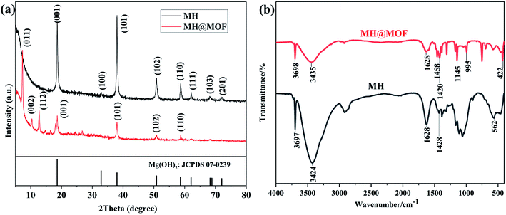 | ||
| Fig. 1 XRD patterns (a) of MH, MH@MOF and standard magnesium hydroxide and FTIR spectra (b) of MH and MH@MOF. | ||
FTIR is further used to characterize the prepared MH and MH@MOF, and the FTIR spectra are shown in Fig. 1b. It can be observed that obvious absorption peaks of MH appear at 3424 cm−1 and in the range of 1428–1628 cm−1, which are attributed to the stretching vibration and bending vibration of –OH of water.50 In addition, the sharp absorption peak at 3697 cm−1 is due to the stretching vibration of –OH of magnesium hydroxide,51 and the stretching vibration peak of Mg–OH52 appears near 562 cm−1. The abovementioned results indicate that magnesium hydroxide is successfully prepared. In addition, not only the abovementioned characteristic peaks exist, but also C–N stretching vibration peaks at 1145 and 995 cm−1, methyl bending vibration peaks at 1458 cm−1, and Zn–N stretching vibration peaks at 422 cm−1 can be observed in the FTIR spectra of MH@MOF.53 The presence of these absorption peaks also proves the successful modification of MH by MOF.
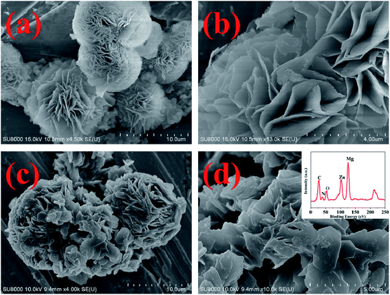
The SEM images of MH and MH@MOF are shown in Fig. 2. It can be clearly seen from Fig. 2a and b that MH has a flower-like structure which is assembled by lamellar agglomeration. At the same time, as can be obtained from Fig. 2c and d, MOF coating are decorated on the surface of MH, but still does not change the overall structure of MH, which also presents a flower-like structure. In addition, as shown in the EDS spectra of MH@MOF (inserted in Fig. 2d), the presence of Zn, N, C, O and Mg elements further indicates the successful formation of MH@MOF.
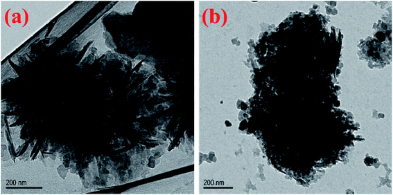
Fig. 3a is the TEM image of MH, which further demonstrates that the flower-like structure is composed of agglomerated magnesium hydroxide lamellae. According to previous research work, the magnesium hydroxide nanoplates are tend to grow in situ and then form the flower-like shape under some special conditions such as high temperature and high pressure.48 It can be seen from the TEM image of MH@MOF (Fig. 3b) that many nanoparticles are coated on the surface of MH. The abovementioned XRD, FTIR, SEM and TEM results all demonstrate that the successful preparation of MH@MOF.
In the above formula: C0 represents the initial concentration of phosphates in the solution (mg L−1); Ce represents the final concentration of phosphates in the solution (mg L−1); V represents the initial volume of the solution (L); m represents the mass of adsorbent (g).
The data of adsorption experiments are listed in Table 2. It is clearly visible that the E and Qe of MH to phosphates achieved to 43.21% and 245.78 mg g−1, respectively, while that of MH@MOF to phosphates only achieved to 23.01% and 130.91 mg g−1. The two parameters of MH@MOF were both lower than MH. This may be due to the fact that MOF was coated on the surface of MH, which reduced the specific surface area of MH and then leading to the reduction of adsorption capacity.58
| Sample | V (L) | C0 (mg L−1) | Ce (mg L−1) | m (g) | E (%) | Qe (mg g−1) |
|---|---|---|---|---|---|---|
| MH | 0.20 | 1137.72 | 646.16 | 0.40 | 43.21 | 245.78 |
| MH@MOF | 0.20 | 1137.72 | 875.89 | 0.40 | 23.01 | 130.91 |
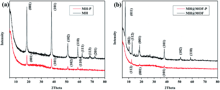
MH and MOF@MH after phosphates adsorption were named as MH–P and MOF@MH–P, respectively, and then collected for analyzing their composition, microstructure and secondary utilization. Fig. 4 shows the XRD patterns of MH and MOF@MH before and after the adsorption experiment. As can be seen from Fig. 4a, compared with MH, the characteristic peaks of MH–P are attenuated, but several basic characteristic peaks of MH are still observed, which indicates that the absorption of phosphates does not destroy the basic structure of MH, but had an inhibitory effect on its crystallization. A similar conclusion can be obtained from Fig. 4b.
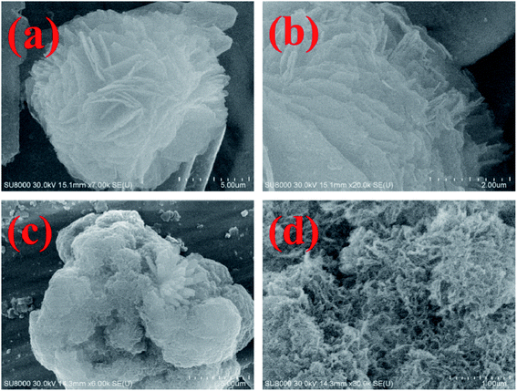
Further observation of the SEM images of MH–P (Fig. 5a and b) and MH@MOF–P (Fig. 5c and d) shows that after phosphates adsorption, except the edge of the lamellar layer is slightly broken, MH remains an intact flower-like structure. However, the morphology of MH@MOF changes apparently, and the original flower-like structure disappears, showing a porous spherical structure.
3.2 Fire behavior of TPU composites
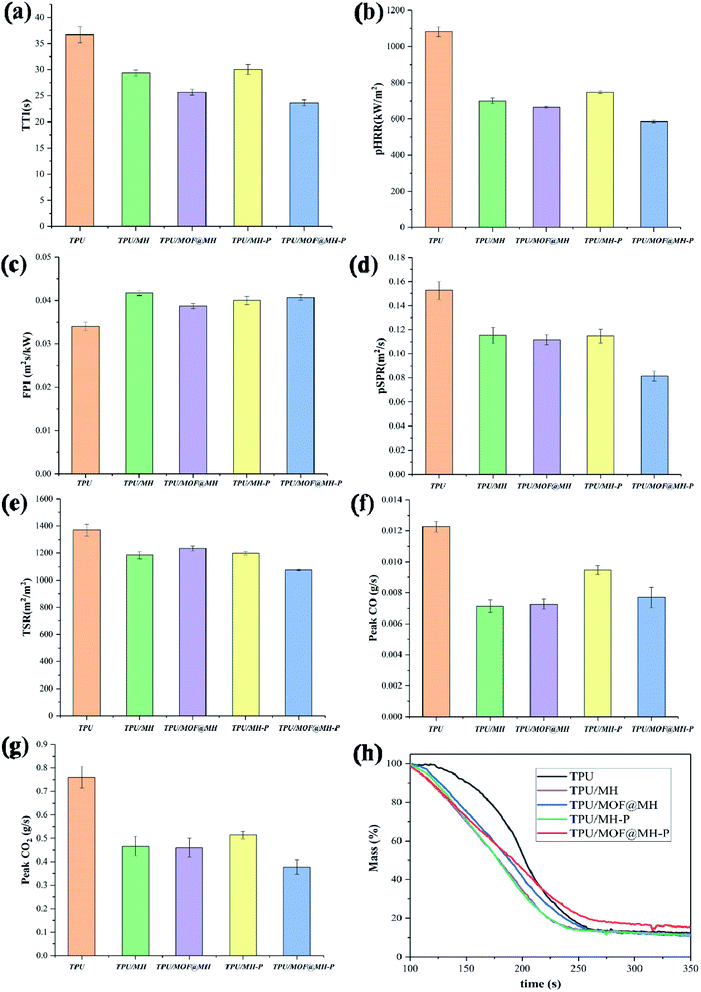 | ||
| Fig. 8 Combustion parameters including TTI (a), pHRR (b), FPI (c), pSPR (d), TSR (e), Peak CO (f), Peak CO2 (g) and Mass (h) of TPU and TPU composites obtained from Cone calorimetry test. | ||
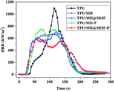
The Fire Performance Index (FPI) is a momentous parameter used to estimate the fire risk, and its value is defined as the ratio of TTI to pHRR. The higher the FPI, the better the fire safety of material.66 The FPI value of pure TPU is 0.034 m2 s kW−1. The addition of MH based flame retardants all increase the FPI value of the TPU composites, especially for MOF@MH–P, indicating that the fire safety of the flame retardant TPU composites has been improved effectively. In addition, as shown in the mass loss curves of TPU and its composites (Fig. 8h), the final residual amount of TPU composites with the addition of MOF@MH–P was increased by 42.0% after combustion, compared with that of pure TPU.
To investigate the combustion behavior of polymer composites, in addition to comparative analysis of their flame retardancy properties, it is also necessary to explore the release of smoke during the combustion process and the toxicity of the smoke released. As shown in Fig. 9, SPR, TSR, CO release rate and CO2 release rate are selected as indicators for flue gas analysis. Combining Fig. 8d, e and 9a, b, pure TPU has a higher peak smoke generation rate (pSPR) of 0.152 m2 s−1 and total smoke release (TSR) of 1369 m2 m−2. The pSPR values of TPU/MH, TPU/MOF@MH, TPU/MH–P, TPU/MOF@MH–P are decreased by 24.3%, 26.3%, 25.0% and 46.7%, respectively. The TSR values of TPU/MH, TPU/MOF@MH, TPU/MH–P, and TPU/MOF@MH–P are decreased to 1186 m2 m−2, 1234 m2 m−2, 1199 m2 m−2 and 1076 m2 m−2, respectively. This manifests that all MH based flame retardants have superior smoke suppression performance, which can inhibit the smoke release during the combustion of TPU composites. Compared with other flame retardants, MH@MOF–P still exhibits excellent smoke suppression effect. The generation of CO and CO2 reflects the smoke toxicity during the combustion process of materials. As shown in Fig. 9c and d, the incorporation of MH based flame retardants can inhibit the release of CO and CO2, making the CO and CO2 release rate curve become gentle. The peak CO release rate values of TPU/MH, TPU/MOF@MH, TPU/MH–P, TPU/MOF@MH–P are decreased by 42.3%, 40.7%, 22.8% and 37.4%, and the peak CO2 release rates are decreased by 38.2%, 39.5%, 32.9% and 50.0%. It is clearly visible that the CO release rate and CO2 release rate of TPU composites reduce strikingly with the addition of MOF@MH–P, and TPU/MOF@MH–P has a good smoke toxicity inhibition effect. The mechanism of MOF@MH–P reducing smoke release and toxicity of TPU composites can be summarized as follows: magnesium hydroxide,16 phosphates67 and MOF39 accelerate the formation of carbon layer during the combustion of TPU composites; the decomposition products of magnesium hydroxide, phosphate further covers the surface of the carbon layer to inhibit TPU combustion, thus reducing the emission rate of flue gas;16 after modifying magnesium hydroxide with MOF, the magnesium hydroxide is well dispersed in TPU matrix, contributing to form a denser carbon layer; the porous structure and large specific surface area of MOF enable it to adsorb the flue gas produced by polymer combustion, greatly inhibiting the flue gas release and reducing the flue gas toxicity of TPU composites;39 the porous structure of MH@MOF–P makes it have a good adsorption capacity of flue gas.
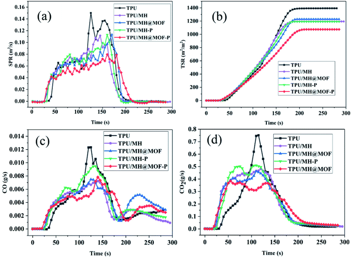 | ||
| Fig. 9 SPR (a), TSR (b), CO release rate (c), and CO2 release rate (d) curves of TPU and TPU composites. | ||
Besides, it is interesting to observe that some flame retardant parameters of TPU/MH–P composites are worse than those of TPU/MH. In contrary, the flame retardancy and smoke suppressing properties of TPU/MH@MOF–P composites are better than those of TPU/MH@MOF composites. This may be due to the fact that the flame retardant mechanism of MH and phosphate is different, and their flame retardant efficiency for TPU is also different.21,31 After MH adsorbs phosphate, the MH–P contains two components: MH and inorganic phosphate, so it has a different flame retardant effect, in comparison with MH, and thereby leading to the variation of combustion data. On the other hand, as a metal organic frame material, MOF has flame retardant effect, and also can improve the interface interaction between the flame retardant and polymer matrix,44 thereby improving the flame retardant efficiency of the flame retardant. In addition, the introduction of MOF made the flame retardant after adsorption of phosphorus (MH@MOF–P) present a porous structure, which can improve the flame retardancy through “labyrinth effect”.68 The good dispersion in the polymer matrix, the combination of MH, inorganic phosphate and MOF as well as the porous structure of MH@MOF–P impart the TPU/MOF@MH–P composites with excellent flame retardancy.
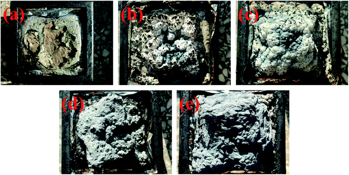 | ||
| Fig. 10 Digital images of char residues from pure TPU (a), TPU/MH (b), TPU/MOF@MH (c), TPU/MH–P (d) and TPU/MOF@MH–P (e) composites after cone test. | ||
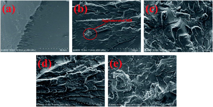
In order to observe the structure of char layer clearly, the SEM images of the carbon surface (Fig. 11) are analyzed. As shown in Fig. 11a, the carbon layer of pure TPU is relatively broken, in which there are large number of cavities and cracks. This makes it easy for heat and smoke to escape during combustion. The carbon layer of TPU/MH is rough, and there are many cracks on it (Fig. 11b). In contrast, the carbon layer of TPU/MH@MOF (Fig. 11c) is smoother, denser, and more continuous, although there are still some holes on it. The carbon structure of TPU/MH–P (Fig. 11d) is similar to that of TPU/MH@MOF, but the number of holes increases slightly. Surprisingly, the introduction of MOF@MH–P into TPU matrix results in continuous, and compact carbon layer (Fig. 11e). The dense carbon layer can block the heat radiated by the flame, slow down the burning speed of polymer and reduce the amount of fuel vapor entering the flame.70,71
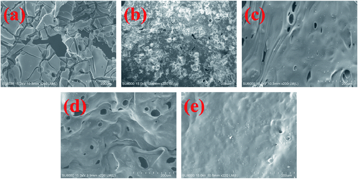 | ||
| Fig. 11 SEM images of char layers from pure TPU (a), TPU/MH (b), TPU/MOF@MH (c), TPU/MH–P (d) and TPU/MOF@MH–P (e) composites. | ||
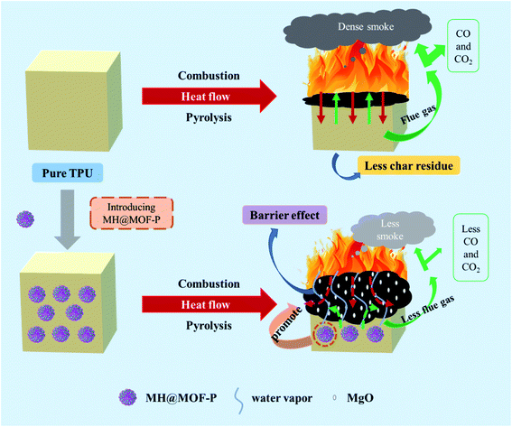
According to the abovementioned analysis, the flame retardancy could be exerted in gas phase and condensed phase simultaneously by the incorporation of MH@MOF–P. As shown in Fig. 12, in gas phase, the magnesium hydroxide in MH@MOF–P will decompose to produce water vapor, reducing the concentration of combustible gas around the material. In condense phase, both MOF and phosphates can facilitate the formation of compact carbon layer. Meanwhile, the decomposition of MH produces MgO and absorbs heat, which can reduce the temperature and increase the densification of carbon layer. The dense carbon layer catalyzed by MH@MOF–P forms a barrier which can not only block heat, but also reduce the release of flue gas, CO, CO2 and other toxic gases. These combined flame retardant mechanisms work together to enhance the fire safety of TPU materials.
4. Conclusion
In order to realize the comprehensive utilization of phosphorus tailings, flower-like magnesium hydroxide was firstly prepared. Then the poor compatibility between MH and polymer matrix was solved by the introduction of MOF. The flower-like structure of MH endowed it with excellent adsorption property and had a promising removal performance of phosphates from sewage. The adsorption test of the phosphates showed that both MH and MOF@MH could remove the phosphorus element in the water efficiently. After the phosphates adsorption experiment, MH–P and MH@MOF–P were recovered and used as effective flame retardants for TPU. The cone calorimetry test results show that the addition of MH based flame retardants including MH, MOF@MH, MH–P and MOF@MH–P can improve the fire safety performance of TPU composites, especially for the MOF@MH–P. Typically, the pHRR, pSPR, TSR, peak CO release rate and peak CO2 release rate of TPU/MOF@MH–P were dramatically decreased by 45.8%, 46.7%, 21.4%, 37.4% and 50.0%, respectively, compared with those of pure TPU. Although the flame retardancy properties of the recycled MH has not been compared to the commercial magnesium hydroxide that is sold in the market for FR applications, the novel strategy proposed in this work is endowed with a great importance to the resource utilization of phosphorus tailings, water eutrophication treatment, sustainable application of adsorbents and flame retardant polymer materials.Conflicts of interest
The authors declare no competing financial interest.Acknowledgements
This work was supported by the Fundamental Research Funds for the Natural Science Fund of Hubei Province (No. 2017CFB315), Fundamental Research Funds of the National University, China University of Geosciences (Wuhan) [CUGGC09], Opening Fund of State Key Laboratory of Fire Science (No. HZ2020-KF10) and National Natural Science Foundation of China (No. 22005277 and 52074247).References
- Y. Yang, Z. Wei, Y. Chen, Y. Li and X. Li, Constr. Build. Mater., 2017, 155, 1081–1090 CrossRef.
- K. Gnandi, G. Tchangbedji, K. Killi, G. Baba and A. I. Ouro Salim, Mine Water Environ., 2005, 24, 215–221 CrossRef.
- Q. Chen, Q. Zhang, A. Fourie and C. Xin, J. Environ. Manage., 2017, 201, 19–27 CrossRef PubMed.
- S. Babel, R. S. Chauhan, N. Ali and V. Yadav, J. Sci. Ind. Res., 2016, 75, 120–123 Search PubMed.
- P. Ranawat, K. M. Kumar and N. K. Sharma, Curr. Sci., 2009, 96, 843–848 Search PubMed.
- K. Zhou, K. Gong, Q. Zhou, S. Zhao, H. Guo and X. Qian, J. Cleaner Prod., 2020, 257, 120606 CrossRef.
- Y. Nie, J. Dai, Y. Hou, Y. Zhu, C. Wang, D. He and Y. Mei, J. Hazard. Mater., 2020, 388, 121748 CrossRef PubMed.
- A. A. Pilarska, L. Klapiszewski and T. Jesionowski, Powder Technol., 2017, 319, 373–407 CrossRef.
- D. Jiang, Y. Yang, C. Huang, M. Huang, J. Chen, T. Rao and X. Ran, J. Hazard. Mater., 2019, 373, 131–140 CrossRef CAS PubMed.
- L. M. Soldatkina, A. N. Purich and V. Menchuk, Adsorpt. Sci. Technol., 2001, 19, 267–272 CrossRef CAS.
- V. Bologo, J. P. Maree and F. Carlsson, Water SA, 2012, 38, 23–28 CrossRef CAS.
- H. Li, S. Liu, J. Zhao and N. Feng, Colloids Surf., A, 2016, 494, 222–227 CrossRef CAS.
- X. Guo, J. Lu and L. Zhang, J. Taiwan Inst. Chem. Eng., 2013, 44, 630–636 CrossRef CAS.
- M. Vafaeifard, S. Ibrahim, K. T. Wong, P. Pasbakhsh, S. Pichiah, J. Choi, Y. Yoon and M. Jang, J. Cleaner Prod., 2019, 216, 495–503 CrossRef CAS.
- J. P. Lv, L. Z. Qiu and B. J. Qu, J. Cryst. Growth, 2004, 267, 676–684 CrossRef.
- K. Zhou, Q. Zhou, K. Gong and J. Zhang, Composites Communications, 2020, 19, 173–176 CrossRef.
- R. N. Rothon and P. R. Hornsby, Polym. Degrad. Stab., 1996, 54, 383–385 CrossRef CAS.
- A. Afzal, M. Usama, I. A. Rashid, Z. Khalid, M. Mohsin, M. F. Shakir and A. Tariq, Mater. Res. Express, 2019, 6, 125352 CrossRef CAS.
- L. Shen, C. Shao, R. Li, Y. Xu, J. Li and H. Lin, Polym. Bull., 2019, 76, 2399–2410 CrossRef CAS.
- H. Tang, K. Chen, X. Li, M. Ao, X. Guo and D. Xue, Funct. Mater. Lett., 2017, 10, 1750042 CrossRef.
- P. R. Hornsby, Fire Mater., 1994, 18, 269–276 CrossRef CAS.
- H. Bacelo, A. M. A. Pintor, S. C. R. Santos, R. A. R. Boaventura and C. M. S. Botelho, Chem. Eng. J., 2020, 381, 122566 CrossRef CAS.
- W. Liu and R. Qiu, J. Chem. Technol. Biotechnol., 2007, 82, 781–786 CrossRef CAS.
- D. Guaya, C. Valderrama, A. Farran, C. Armijos and J. Luis Cortina, Chem. Eng. J., 2015, 271, 204–213 CrossRef CAS.
- Y. He, H. Lin, Y. Dong, B. Li, L. Wang, S. Chu, M. Luo and J. Liu, Chem. Eng. J., 2018, 347, 669–681 CrossRef CAS.
- J. Lalley, C. Han, X. Li, D. D. Dionysiou and M. N. Nadagouda, Chem. Eng. J., 2016, 284, 1386–1396 CrossRef CAS.
- Y. Su, W. Yang, W. Sun, Q. Li and J. K. Shang, Chem. Eng. J., 2015, 268, 270–279 CrossRef CAS.
- J. Zhang, Z. Shen, W. Shan, Z. Mei and W. Wang, J. Hazard. Mater., 2011, 186, 76–83 CrossRef CAS.
- M. R. Awual, J. Cleaner Prod., 2019, 228, 1311–1319 CrossRef CAS.
- K. Gong, K. Zhou and B. Yu, Appl. Surf. Sci., 2020, 504, 144314 CrossRef CAS.
- B. Schartel, Materials, 2010, 3, 4710–4745 CrossRef CAS.
- J. Green, J. Fire Sci., 1996, 14, 353–366 CrossRef CAS.
- S. V. Levchik and E. D. Weil, J. Fire Sci., 2006, 24, 345–364 CrossRef CAS.
- H. Liu, H. Wu, Q. Song, J. Zhang, W. Li and H. Qu, J. Therm. Anal. Calorim., 2020, 141, 1341–1350 CrossRef CAS.
- J. Noh, I. Kang, J. Choi, H. Fatima, P. J. Yoo, K. W. Oh and J. Park, Polym. Bull., 2016, 73, 2855–2866 CrossRef CAS.
- D. Zhu, X. Nai, S. Lan, S. Bian, X. Liu and W. Li, Appl. Surf. Sci., 2016, 390, 25–30 CrossRef CAS.
- S. Zhou, V. Apostolopoulou-Kalkavoura, M. V. T. Da Costa, L. Bergstrom, M. Stromme and C. Xu, Nano-Micro Lett., 2020, 12(9) DOI:10.1007/s40820-019-0343-4.
- Y. Hou, W. Hu, Z. Gui and Y. Hu, Ind. Eng. Chem. Res., 2017, 56, 2036–2045 CrossRef CAS.
- Y. Hou, W. Hu, X. Zhou, Z. Gui and Y. Hu, Ind. Eng. Chem. Res., 2017, 56, 8778–8786 CrossRef CAS.
- A. Li, W. Xu, R. Chen, Y. Liu and W. Li, Composites, Part A, 2018, 112, 558–571 CrossRef CAS.
- H. Guo, Y. Wang, C. Li and K. Zhou, RSC Adv., 2018, 8, 36114–36122 RSC.
- Y. Hou, L. Liu, S. Qiu, X. Zhou, Z. Gui and Y. Hu, ACS Appl. Mater. Interfaces, 2018, 10, 8274–8286 CrossRef CAS.
- F. Seidi, M. Jouyandeh, M. Taghizadeh, A. Taghizadeh, H. Vahabi, S. Habibzadeh, K. Formela and M. R. Saeb, Materials, 2020, 13, 2881 CrossRef PubMed.
- H. Wang, H. Qiao, J. Guo, J. Sun, H. Li, S. Zhang and X. Gu, Composites, Part B, 2020, 182, 107498 CrossRef CAS.
- S. Wang, R. Gao and K. Zhou, J. Colloid Interface Sci., 2019, 536, 127–134 CrossRef CAS PubMed.
- B. Xu, W. Xu, G. Wang, L. Liu and J. Xu, Polym. Adv. Technol., 2018, 29, 1733–1743 CrossRef CAS.
- Y. Zheng, Y. Lu and K. Zhou, J. Therm. Anal. Calorim., 2019, 138, 905–914 CrossRef CAS.
- D. Ghanbari, M. Salavati-Niasari and M. Sabet, Composites, Part B, 2013, 45, 550–555 CrossRef CAS.
- S. R. Venna, J. B. Jasinski and M. A. Carreon, J. Am. Chem. Soc., 2010, 132, 18030–18033 CrossRef CAS.
- S. Guo, L. Yang, B. Dai, F. Geng, Z. Yang, P. Wang, G. Gao, L. Xu, J. Han, V. Ralchenko and J. Zhu, Mater. Lett., 2019, 236, 448–451 CrossRef CAS.
- K. Govindaraju, K. V. Anand, S. Anbarasu, J. Theerthagiri, S. Revathy, P. Krupakar, G. Durai, M. Kannan and K. S. Subrarnanian, Mater. Chem. Phys., 2020, 239, 122007 CrossRef CAS.
- W. Zhang, P. Zhang, Y. Wang and J. Li, Integr. Ferroelectr., 2015, 163, 148–154 CrossRef CAS.
- N. Li, L. Zhou, X. Jin, G. Owens and Z. Chen, J. Hazard. Mater., 2019, 366, 563–572 CrossRef CAS PubMed.
- X. Huang, T. Wu, Y. Li, D. Sun, G. Zhang, Y. Wang, G. Wang and M. Zhang, J. Hazard. Mater., 2012, 219, 82–88 CrossRef.
- S. Tanada, M. Kabayama, N. Kawasaki, T. Sakiyama, T. Nakamura, M. Araki and T. Tamura, J. Colloid Interface Sci., 2003, 257, 135–140 CrossRef CAS.
- Y. Makita, A. Sonoda, Y. Sugiura, A. Ogata, C. Suh, J. Lee and K. Ooi, Sep. Purif. Technol., 2020, 241, 116707 CrossRef CAS.
- T. Sheng, Z. Zhang, Y. Hu, Y. Tao, J. Zhang, Z. Shen, J. Feng and A. Zhang, Environ. Sci. Pollut. Res., 2019, 26, 7102–7114 CrossRef CAS PubMed.
- L. Lin, Z. Li, X. Song, Y. Jiao and C. Zhou, Mater. Lett., 2018, 218, 201–204 CrossRef CAS.
- H. Gui, X. Zhang, Y. Liu, W. Dong, Q. Wang, J. Gao, Z. Song, J. Lai and J. Qiao, Compos. Sci. Technol., 2007, 67, 974–980 CrossRef CAS.
- Y. Xu, M. Chen, X. Ning, X. Chen, Z. Sun, Y. Ma, J. Yu, Z. Zhang, X. Bo, L. Yang and Z. Chen, J. Therm. Anal. Calorim., 2014, 115, 689–695 CrossRef CAS.
- K. Zhou, R. Gao and X. Qian, J. Hazard. Mater., 2017, 338, 343–355 CrossRef PubMed.
- G. Cumming, F. Fidler and D. L. Vaux, J. Cell Biol., 2007, 177, 7–11 CrossRef CAS PubMed.
- S. Heinen, J. L. Cuellar-Camacho and M. Weinhart, Acta Biomater., 2017, 59, 117–128 CrossRef CAS PubMed.
- S. Zhao, J. Yin, K. Zhou, Y. Cheng and B. Yu, Composites, Part A, 2019, 122, 77–84 CrossRef CAS.
- F. Qi, M. Tang, N. Wang, N. Liu, X. Chen, Z. Zhang, K. Zhang and X. Lu, RSC Adv., 2017, 7, 31696–31706 RSC.
- S. Fang, Y. Hu, L. Song, J. Zhan and Q. He, J. Mater. Sci., 2008, 43, 1057–1062 CrossRef CAS.
- S. Horold, Polym. Degrad. Stab., 1999, 64, 427–431 CrossRef CAS.
- Z. Huang, S. Jiang, N. Hong, Y. Zhu, Y. Hou and Y. Hu, Composites, Part A, 2017, 95, 337–345 CrossRef CAS.
- L. Ai, S. Chen, J. Zeng, L. Yang and P. Liu, ACS Omega, 2019, 4, 3314–3321 CrossRef CAS PubMed.
- D. Hu, Q. Zhou and K. Zhou, J. Appl. Polym. Sci., 2019, 136, 48220 CrossRef.
- X. Wang, E. N. Kalali, J. Wan and D. Wang, Prog. Polym. Sci., 2017, 69, 22–46 CrossRef CAS.
| This journal is © The Royal Society of Chemistry 2021 |

