 Open Access Article
Self-shutdown function induced by sandwich-like gel polymer electrolytes for high safety lithium metal batteries†
Binxuan Xiea,
Shimou Chen *bc,
Yong Chend and
Lili Liu*a
aCollege of Chemistry and Materials Engineering, Beijing Technology and Business University, Beijing, 100048, China. E-mail: liulili@btbu.edu.cn
bInstitute of Process Engineering, Chinese Academy of Sciences, Beijing, 100190, China. E-mail: chenshimou@ipe.ac.cn
cState Key Laboratory of Chemical Resource Engineering, Beijing University of Chemical Technology, Beijing, 100029, China
dSchool of Chemical & Environmental Engineering, China University of Mining & Technology, Beijing 100083, China
First published on 14th April 2021
Abstract
Lithium-ion batteries using either liquid electrolytes or solid electrolytes have been extensively studied in recent years, but both of these encounter safety risks such as flammability of liquid electrolytes and uncontrolled dendrite growth. In this study, a sandwich gel polymer electrolyte (SGPE) with a thermal shutdown function was developed to resolve the safety issues. By adjustment of surface pore size of the SGPE, lithium dendrite growth is suppressed. Due to the sandwich structure design, the SGPE can effectively respond to an overheating environment, regulate lithium ion transport and inhibit the penetration of lithium dendrite, demonstrating a remarkably high safety of the batteries, especially at high temperature or under thermal runaway circumstances. In addition, the LiFePO4/SGPE/Li battery exhibits a high reversible capacity of 135 mA h g−1 at 1C and maintains high capacity retention (>95%) after 200 charge–discharge cycles. This study shows a great advantage to handle thermal abuse and a stable lithium anode, suggesting a promising approach to the high safety lithium metal batteries.
1. Introduction
Due to the unique merits of portability, high energy density, low self-discharge rate and no memory effect, lithium-ion batteries (LIBs) have been monopolizing the consumer electronics market for almost 30 years.1,2 Lithium metal, with ultrahigh theoretical specific capacity (3860 mA h g−1) and extremely low potential (−3.040 V vs. standard hydrogen electrode), is hailed as the promising step forward in maximizing energy density of state-of-the-art batteries.3 However, the application of lithium metal batteries (LMBs) using non-aqueous liquid electrolytes cannot achieve satisfactory safety performance. In detail, the high reactivity of lithium metal with organic carbonate promotes the continuous consumption of lithium metal, causing the degradation of coulombic efficiency.4–6 Moreover, uncontrolled dendrite growth resulting from heterogeneous electrodeposition would penetrate the separator, leading to a series of exothermic reactions, causing a short circuit and local overheating in the battery, and could even induce combustion and explosion in the commercialized lithium battery packs.7To make better use of Li metal, different strategies have been utilized, including modification of electrolyte composition (lithium salt,8 solvents,9 and additives10–12), application of advanced electrolytes13–16 and 3D lithium metal anode.17 During these strategies, advanced electrolytes, like solid-state electrolytes (SSEs) with non-flammable and stable merits, considered to be the most promising way to solve security issues.18–21 However, the low ionic conductivity at room temperature and the high interfacial impedance have limited SSEs.22 The electrolyte development is operating in a paradox: on the one hand, using SSEs is understood to be a fundamental way to ensure safety, but on the other hand, the high performance of liquid electrolyte at room temperature is difficult to give up. Therefore, gel polymer electrolytes (GPEs) have been proposed to combine the advantages of high performance of liquid and high safety of solid.23–25 But because GPE still contains a considerable amount of flammable liquid electrolytes and host materials with thermal intolerance, the security issues are also plaguing at high temperature.26 Hence, high performance GPEs with high safety should be explored.
Strategies to achieve batteries with high security can be divided into two categories, one is external strategy, the other is internal strategy. Positive temperature coefficient (PTC) resistors are applying on commercial LIBs to shut down by undergoing a sharp increase in resistance as pressure and temperature out of control.27,28 However, such external devices are dull for transient change of pressure and temperature. Therefore, internal thermal response materials, with high sensitivity, fast response speed, self-shutdown function, are smart in preventing thermal runaway and have been developed,29,30 giving a smart and effective approach to enable LMBs with fast self-protection, preventing combustion and explosion at precise threshold.31–33 Thermally responsive materials have broad applications in batteries, not only as components of the electrolytes,33 but also as safe binders,34 reversible switch collectors27,28 and as self-shutdown additives,35 exhibiting an intrinsic mechanism for shutdown device operation as the temperature increases beyond a given threshold. However, these strategies often require complex multi-step synthesis processes and additional flame-retardant components in the electrolyte which would increase the weight of the whole devices but do not contribute to the energy density.31,36,37 Recently, many works have reported on the method of structural modification, demonstrating application prospects in different aspects.38,39 In addition, the structurally designed electrolyte can also improve battery safety performance.31,40 Therefore, designing the electrolyte structure is an effective way to achieve high-performance and high-safety LMBs.
Herein, a novel high-safety sandwich gel polymer electrolyte (SGPE) was synthesized. The obtained SGPE consists of two porous poly(vinylidene-fluoride-hexafluoropropylene) (PVDF-HFP)/poly-pentaerythritol tetraacrylate (PETEA) polymer layers (named PVDF-HFP@SiO2-PETEA) contacting with electrodes to ensure safety and a layer constructed by poly-PETEA between them to create internal space to storage liquid electrolytes. Through innate intolerance of PVDF-HFP membrane, this SGPE forms the favorable protection layer on both electrodes, resulting in self-shutdown behavior by transforming the unstable PVDF-HFP membrane into thermal-responsive layer. In the absence of extra components, through the adjustment of surface morphology and electrolyte sandwich structure design, the prepared SGPE exhibited rapid and sensitive self-shutdown response under high temperature stimulation (80 °C), demonstrating the intrinsic safety characteristics of its autonomous response. Furthermore, the SGPE is proven to have a high liquid electrolyte uptake ratio (86.2%), long-term stable deposition of lithium metal without conspicuous dendrite growth (over 1000 h). These results well indicate the extraordinary security and electrochemical properties of this SGPE and its promising applications in high safety LMBs.
2. Experiment
2.1 Materials
N-Methyl-2-pyrrolidone (NMP) (Aladdin), poly(vinylidene-fluoride-hexafluoropropylene) (PVDF-HFP) (MW = 400![[thin space (1/6-em)]](https://www.rsc.org/images/entities/char_2009.gif) 000, Sigma-Aldrich), pentaerythritol tetraacrylate (PETEA) (MW = 352.34, Tokyo Chemical Industry Co., Ltd.), SiO2 (Aladdin), azobisisobutyronitrile (AIBN) (99%, Shanghai Macklin Biochemical Co., Ltd.), commercial separators (Celgard 2400 separator, thickness: 25 μm). Liquid electrolytes (1 M LiPF6 in EC/DMC/EMC = 1/1/1, v/v/v), ethylene carbonate (EC) and diethyl carbonate (DEC) were purchased from Shanghai Songjing New Energy Technology Co., Ltd. Lithium iron phosphate (LiFePO4), polyvinylidene fluoride (PVDF), conductive carbon (Super P) and lithium foils were purchased from Shenzhen Kejing Star Tech Co., Ltd. All chemicals are used directly without additional treatment.
000, Sigma-Aldrich), pentaerythritol tetraacrylate (PETEA) (MW = 352.34, Tokyo Chemical Industry Co., Ltd.), SiO2 (Aladdin), azobisisobutyronitrile (AIBN) (99%, Shanghai Macklin Biochemical Co., Ltd.), commercial separators (Celgard 2400 separator, thickness: 25 μm). Liquid electrolytes (1 M LiPF6 in EC/DMC/EMC = 1/1/1, v/v/v), ethylene carbonate (EC) and diethyl carbonate (DEC) were purchased from Shanghai Songjing New Energy Technology Co., Ltd. Lithium iron phosphate (LiFePO4), polyvinylidene fluoride (PVDF), conductive carbon (Super P) and lithium foils were purchased from Shenzhen Kejing Star Tech Co., Ltd. All chemicals are used directly without additional treatment.
2.2 Synthesis of microporous PVDF-HFP@SiO2 membranes
Briefly, PVDF-HFP (0.5 g) and SiO2 (0.005 g) were dissolved in 5 g solvent (EC/DEC = 1/1). Stirring at 50 °C for 6 hours to form a translucent solution with uniform texture. After 30 minutes ultrasonication, the viscous precursor solution was evenly casted on glass plate, followed by evaporating the solvents at room temperature for 24 h to yield self-standing polymer membranes, named PVDF-HFP@SiO2 membranes.2.3 PETEA monomer solution preparation
1 ml PETEA monomer and 0.01 g AIBN were added to 9 ml solvent (EC/DEC = 1/1, v/v), and then stirred at 25 °C for 5 min to form a uniform transparent monomer solution. At this time, the ratio of PETEA monomer to solvent is 1![[thin space (1/6-em)]](https://www.rsc.org/images/entities/char_2009.gif) :
:![[thin space (1/6-em)]](https://www.rsc.org/images/entities/char_2009.gif) 9. Adjusting the ratio of PETEA monomer to solvent, 2 ml PETEA monomer and 0.02 g AIBN were added in 8 ml solvent, then stirred at 25 °C for 5 min to form a uniform transparent monomer solution, the ratio of monomer solution to solvent at this time is 2
9. Adjusting the ratio of PETEA monomer to solvent, 2 ml PETEA monomer and 0.02 g AIBN were added in 8 ml solvent, then stirred at 25 °C for 5 min to form a uniform transparent monomer solution, the ratio of monomer solution to solvent at this time is 2![[thin space (1/6-em)]](https://www.rsc.org/images/entities/char_2009.gif) :
:![[thin space (1/6-em)]](https://www.rsc.org/images/entities/char_2009.gif) 8. Similarly, the adjusted ratios of monomer to solvent are 3
8. Similarly, the adjusted ratios of monomer to solvent are 3![[thin space (1/6-em)]](https://www.rsc.org/images/entities/char_2009.gif) :
:![[thin space (1/6-em)]](https://www.rsc.org/images/entities/char_2009.gif) 7, 4
7, 4![[thin space (1/6-em)]](https://www.rsc.org/images/entities/char_2009.gif) :
:![[thin space (1/6-em)]](https://www.rsc.org/images/entities/char_2009.gif) 6 and 5
6 and 5![[thin space (1/6-em)]](https://www.rsc.org/images/entities/char_2009.gif) :
:![[thin space (1/6-em)]](https://www.rsc.org/images/entities/char_2009.gif) 5, respectively.
5, respectively.
2.4 SGPE membrane synthesis
Two pieces of PVDF-HFP@SiO2 membranes were stacked together by a tableting device, followed by immersed into the above-prepared PETEA monomer solution. The swelling process kept for 30 min, to ensure that PETEA monomer diffuse into the pores of PVDF-HFP@SiO2 membranes and the confined space between the two PVDF-HFP@SiO2 membranes. After removing the excess PETEA on the outside of the membranes, it was transferred to vacuum drying box at 60 °C for 6 h, the absorbed PETEA monomer will polymerized under high temperature, obtaining the final product of sandwich SGPE membrane. It is worth noting that the well-designed amount of PETEA monomer absorbed on the PVDF-HFP@SiO2 membranes can modify the surface pore size and avoid too many monomers blocking the pores. At the same time, the polymerization of PETEA monomer in the confined space between the two PVDF-HFP@SiO2 membranes can effectively connect the PVDF-HFP@SiO2 matrix membranes on both sides, and create a loose intermediate structure in the middle for better storage of liquid electrolyte. After polymerization, the designed SGPE membrane consists of two parts, self-shutdown layers (named PVDF-HFP@SiO2-PETEA) on both sides and a loose structure in the middle.2.5 Activation of SGPEs
Finally, the SGPE was obtained by transferring SGPE membrane into a sample bottle and soaking with liquid electrolyte (1 M LiPF6 in EC/DMC/EMC = 1/1/1) for 6 h. Celgard 2400 and single layer PVDF-HFP@SiO2 membrane were used to do the controlled experiments.2.6 Characterizations
The Fourier transform infrared (FTIR) spectra were performed on a VERTEX 80 V Fourier transform infrared spectrometer (Brucker, USA). The contact angle tests were recorded using a Drop Shape Analysis System DSA10-MK2 (Kruess, Germany). The morphology and structure of the SGPE membranes were characterized by a scanning electron microscope (SEM) (Haitich SU8020, Japan) with an acceleration voltage of 5 kV. The thermal property of the SGPE-40 and PVDF-HFP@SiO2 were examined by thermogravimetric analyzer (TGA, Setaram Labsys) with a heating rate of 5 °C min−1 from 25 °C to 600 °C. The X-ray diffractometer (XRD) (Bruker D8 Focus) with a Ni-filtered Cu Kα radiation (λ = 0.15406 nm) source was used to analyze the crystalline state of SGPE-40 and PVDF-HFP@SiO2 membranes.The electrolytes uptake was calculated by following equation:
| Electrolyte uptake (%) = (M − M0)/M0 × 100% |
The porosity was calculated by the following equation:
| Porosity (%) = (Ww − Wd/ρ)/Vd × 100% |
The SGPE membrane and Celgard 2400 separator fully taking liquid electrolyte were heated by an open flame to test its safety performance. The thermal shrinkage ratio was calculated according to the following equation:
| Thermal shrinkage (%) = (S − S0)/S0 × 100% |
2.7 Electrode preparation and battery assembly
The cathode was prepared by casting muddy precursor (LiFePO4![[thin space (1/6-em)]](https://www.rsc.org/images/entities/char_2009.gif) :
:![[thin space (1/6-em)]](https://www.rsc.org/images/entities/char_2009.gif) Super P
Super P![[thin space (1/6-em)]](https://www.rsc.org/images/entities/char_2009.gif) :
:![[thin space (1/6-em)]](https://www.rsc.org/images/entities/char_2009.gif) PVDF = 8
PVDF = 8![[thin space (1/6-em)]](https://www.rsc.org/images/entities/char_2009.gif) :
:![[thin space (1/6-em)]](https://www.rsc.org/images/entities/char_2009.gif) 1
1![[thin space (1/6-em)]](https://www.rsc.org/images/entities/char_2009.gif) :
:![[thin space (1/6-em)]](https://www.rsc.org/images/entities/char_2009.gif) 1 in NMP) in Al foil. Then, vacuum dried for 12 hours and cut into small discs. The areal loading of LiFePO4 was 2–3 mg cm−2. Lithium foil was used as anode. The Li metal battery was assembled by sandwiching SGPE between cathode and Li metal in CR2025 coin cell in glove box.
1 in NMP) in Al foil. Then, vacuum dried for 12 hours and cut into small discs. The areal loading of LiFePO4 was 2–3 mg cm−2. Lithium foil was used as anode. The Li metal battery was assembled by sandwiching SGPE between cathode and Li metal in CR2025 coin cell in glove box.
2.8 Electrochemical characterization
For conductivity measurement, SGPE was assembled into a coin cell with stainless-steel blocking electrodes. Electrochemical impedance spectroscopy (EIS) was carried out at 25 °C on the electrochemical station Metrohm Autolab (PGSTAT302N) under a frequency range from 1 MHz to 1 Hz. The ionic conductivity (σ) was calculated by the following equation:| σ = L/(R × As) |
For lithium stripping/plating test, SGPE was assembled into a coin cell with lithium foils on both sides. The galvanostatic cycling tests were performed on the Neware battery test system at 25 °C between 2.5 V to 3.9 V. The rate performance of LFP/Li battery was conducted at the rates of 0.2C, 0.5C, 1C, 2C, 3C and back to 0.2C between 2.5 V to 3.9 V for 5 cycles for each rate. Noted that similar electrochemical measurements were also carried out on the Celgard 2400 separators and PVDF-HFP@SiO2 membranes.
3. Results and discussion
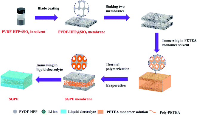
Well-designed SGPE consists of two parts: self-shutdown layers (named PVDF-HFP@SiO2-PETEA) on both sides and a loose structure layer in the middle. PVDF-HFP@SiO2-PETEA layers on both sides are used to ensure safety, and the loose middle layer poly-PETEA is used to connect the self-shutdown layers on both sides and build a loose electrolyte-philic structure in the middle because PETEA is usually used to form self-standing structure in in situ polymerized electrolyte.41–43 Add a small amount (1%) of SiO2 to enhance the mechanical properties, and finally obtain a polymer skeleton with high porosity, which can form a gel electrolyte with traditional commercial electrolytes, which was shown in Fig. S1.†In order to obtain a porous SGPE membrane, we use PVDF-HFP@SiO2 as the initial framework, select ester monomers, and regulate monomer polymerization to form a porous sandwich membrane with interpenetrating networks. The synthesis process of the SGPE is illustrated in Fig. 1. The obtained SGPE membranes with different monomer concentration are denoted as SGPE-X (X = 0, 10, 20, 30, 40, 50). It can be seen from Fig. S2a† that the initial PVDF-HFP@SiO2 membrane has the largest porosity. As the polymerized monomer content increases, the porosity gradually decreases, which should be due to the poor dispersion of polymer chains caused by the excessive polymerization of the PETEA monomer.44 Compared with the work of other researchers,45 the reduction in porosity in this work is smaller, which is attributed to the lower dosage of polymerized monomer (0.0175 g PETEA monomer per SGPE membrane, mass ratio is 13.9%). When the concentration is 0, the two-layer PVDF-HFP@SiO2 cannot be used as an effective electrolyte membrane, but as the concentration increases, SGPE with a uniform surface and a large cavity inside was prepared. In the comparison of a series of SGPE-X, with the increasing of the X, the porosity and pore size of the SGPE surface gradually decrease, which can be attributed to the increasing number of PETEA and the modification of the pore size by polymerization (Fig. S3†). Combining those data above and the cycling performance test (Fig. S4†), the SGPE-40 is selected as an optimizing sample and studied in the following work.
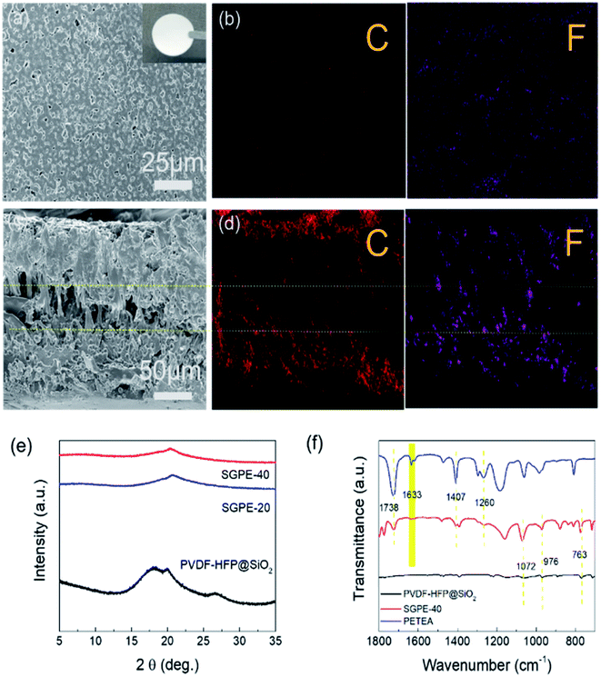
As shown in Fig. 2a, the SGPE-40 has a smooth and uniform texture with porous structure, its pore size was measured to be around 2000 nm, which is much smaller than that of the PVDF-HFP@SiO2. Due to the synergy effect of different volatility points of different solvents and thermal polymerization after swelling, SGPE-40 membrane shows uniform pore distribution without any conspicuous crystallized phase. It still clearly shows the unique sandwich composite structure in the cross-section SEM images (Fig. 2c), a poly-PETEA layer with loose structure confined between two PVDF-HFP@SiO2-PETEA layers. The special structure with functional tri-layer helps to storage the electrolyte firmly and enhance the wettability with liquid electrolytes and promote homogenous Li+ distribution.46 The cross-section SEM image shows that the thickness of SGPE-40 was 200 μm. The EDX test also showed the same results. The element distribution of C, F was homogeneous and uniform on the surface (Fig. 2b), but in the cross-section image (Fig. 2d), the element distribution has clear boundary that dense on both sides and insufficient in the middle, reflecting the loose structure in the middle layer, providing plenty of space for electrolyte storage.
It is noted that PETEA monomer has four active sites in a symmetrical star structure to form a three-dimensional network with high crosslink density, improves mechanical character.41,47,48 It can be obviously observed from Fig. 2e that three remarkable peaks around at 18.3°, 20.0° and 26.6° are assigned to the polymer matrix of PVDF-HFP. However, the intensity of peak gets broadened and weakened when SGPE obtained, which indicates the reduction of crystallinity. However, the peaks intensity attenuates gradually because of the blending of poly-PETEA, which reduces the crystallinity and enhances the creep of the segment.49,50 When the concentration of polymerized monomer is 40%, the strongest peak intensity attenuation is obtained. Fig. 2f compares the FTIR spectra of PETEA, PVDF-HFP@SiO2 and SGPE-40. It is clear that the appearance at 1260 cm−1 (C–O antisymmetric stretching), 1407 cm−1 (CH2 bending) and 1738 cm−1 (C![[double bond, length as m-dash]](https://www.rsc.org/images/entities/char_e001.gif) O stretching) are in good accordance with previous work.43 For PVDF-HFP, α-phase of PVDF-HFP appears at 1072 cm−1, 976 cm−1 and 763 cm−1.51 The prepared SGPE-40 showed the corresponding characteristic peaks of the PETEA monomer, indicating that PETEA is successfully compounded inside SGPE-40. It is worth mentioning that the C
O stretching) are in good accordance with previous work.43 For PVDF-HFP, α-phase of PVDF-HFP appears at 1072 cm−1, 976 cm−1 and 763 cm−1.51 The prepared SGPE-40 showed the corresponding characteristic peaks of the PETEA monomer, indicating that PETEA is successfully compounded inside SGPE-40. It is worth mentioning that the C![[double bond, length as m-dash]](https://www.rsc.org/images/entities/char_e001.gif) C bonds peak at 1633 cm−1 was not found in the SGPE-40, indicating that a three-dimensional structure composed of poly-PETEA had connected the self-shutdown layer on the both sides and form the sandwich structure.41
C bonds peak at 1633 cm−1 was not found in the SGPE-40, indicating that a three-dimensional structure composed of poly-PETEA had connected the self-shutdown layer on the both sides and form the sandwich structure.41
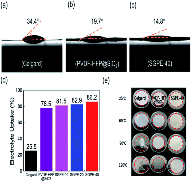
The contact angle of liquid electrolyte on the Celgard 2400, PVDF-HFP@SiO2 and SGPE-40 membrane have been illustrated in Fig. 3a–c to verify the interfacial compatibility. The values for Celgard 2400 and PVDF-HFP@SiO2 membrane are 34.4° and 19.7°, respectively, which prove that PVDF-HFP matrix has good affinity for electrolyte than Celgard. Moreover, the contact angle on SGPE-40 membrane is 14.8°, indicating that its internal loose structure provides a unique absorption and storage of liquid electrolyte.52 The same result was also proved in the electrolyte uptake test, as shown in Fig. 3d. Celgard, due to its poor compatibility with liquid electrolytes, its electrolyte uptake ratio is 25.5%. In contrast, thanks to their special porous structure, the PVDF-HFP@SiO2 and SGPE-10, SGPE-20 and SGPE-40 have maintained high absorption rates, the electrolyte uptake ratio are 78.4%, 81.5%, 82.9% and 86.2%, respectively. With these big amounts of liquid electrolytes, they could effectively accelerate ion transport.
The thermal stability of membranes is crucial to the safety of batteries. The thermal stability of these membranes was further evaluated by treating membranes on hot plate at different temperatures ranging from 25 °C to 120 °C. From Fig. 3e, Celgard shrinks slightly at 60 °C, severe shrinkage occurs at 90 °C, and melt at 120 °C. In contrast, PVDF-HFP@SiO2 and SGPE-40 show almost no morphology changes even at 120 °C, indicating that it can maintain dimensional stability under high temperature, better isolate cathode and anode to prevent short circuit. TGA analysis showed that both SGPE-40 and PVDF-HFP@SiO2 have higher decomposition temperature (as shown in Fig. S5†). Fig. S6† exhibits the combustion test between SGPE-40 and the Celgard separator both full of liquid electrolytes. When the Celgard 2400 close to the fire, it immediately burned, melt, and eventually turned into black debris in few seconds. For the SGPE-40, it burns quickly, and after 5 s, it extinguishes immediately, still maintains 43% effective area after burning. Therefore, the SGPE-40 shows better thermal stability.
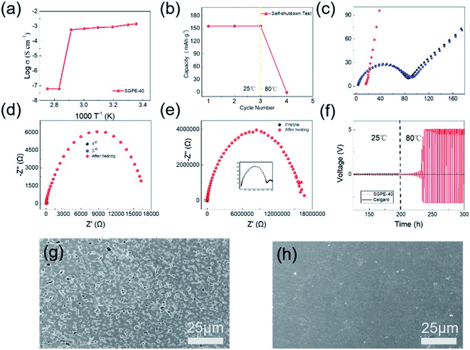
In order to study the thermal self-shutdown performance of SGPE-40, we first assembled SS/SS battery to detect the ionic conductivity at different temperature, which is shown in Fig. 4a. At room temperature, the SGPE-40 exhibits a very high conductivity (1.45 × 10⁻³ S cm−1), and the conductivity reduces slightly with the increasing temperature until to 70 °C. It is worth noting that when the temperature rises to 80 °C, the conductivity appears a huge dropdown, which directly approaches 6.1 × 10⁻⁸ S cm−1, and the same conductivity also obtained at 90 °C, indicating that the battery assembled with SGPE-40 can not operate under high temperature. The sudden drop in ion conductivity indicates that there is an open circuit inside the battery at this time. To better explore the reason, we assembled the LFP/Li battery and studied its charge and discharge properties at 25 °C and 80 °C, as shown in the Fig. 4b. The LFP battery has experienced a stable discharge specific capacity at room temperature, which are 156.0 mA h g−1, 156.4 mA h g−1, 156.1 mA h g−1. In sharp contrast, when the temperature rises to 80 °C, the specific discharge capacity of the battery drops to 0. At this time, the open circuit voltage of the battery is 3.3 V, indicating that the SGPE-40 has isolated the electrodes, resulting in the occurrence of open circuit. A more rigorous test method is to observe the behavior of plating/stripping of lithium on both lithium electrodes at different temperatures. The same result also occurred on the symmetrical lithium battery (Fig. 4f). At room temperature, the battery maintained a stable voltage polarization about 25 mV, lasting 200 h. However, when the temperature rises to 80 °C, the voltage line of the battery using Celgard membrane quickly drops to 0, indicating the direct contact between the electrodes caused by the thermal shrinkage of the Celgard, according to the previous thermal shrinkage test. However, the voltage curve of the battery using SGPE-40 rises rapidly to 5 V, demonstrating no short circuit between the two electrodes. The AC impedance spectroscopy (Fig. 4c and d) show the occurrence of open circuit. The SEM image (Fig. 4h) shows no pore structure on the SGPE-40 membrane surface, which proves that the pore is closed after hot treatment. When the temperature increases, its high-temperature unstable porous PVDF-HFP@SiO2-PETEA layer of SGPE-40 quickly closes the pore, cutting off the transmission of lithium ions, and preventing thermal runaway. It is worth mentioning that the rapid increase in impedance of Li/Li using SGPE-40 (Fig. 4e) also illustrates the self-shutdown function of the SGPE-40.
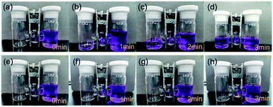
The self-shutdown visualization experiment was used to verify the autonomous response safety features of SGPE-40. As shown in the Fig. 5, we dye the commercial liquid electrolyte with blue pigment and store them in right side of the H-electrolytic cell. Before the heat treatment, the liquid electrolyte has good wettability to the SGPE-40 membrane, and the electrolyte quickly diffuses to another side, which means that SGPE-40 has good wettability. As shown in Fig. 5a–d. The opposite is that after the heat-treat process, when the SGPE-40 membrane is in contact with the liquid electrolyte, since the surface has no porous structure, it essentially becomes a blocking device, which can neither absorb liquid nor undergo mass transfer (Fig. 5e–h). It can be seen in Fig. S11† that when the temperature range is between 30–80 °C, the battery maintains the capability of lighting the LED device. However, after keeping for more than 8 min in an environment of 80 °C, the LED doesn't work, indicating that the self-shutdown behavior has occurred.
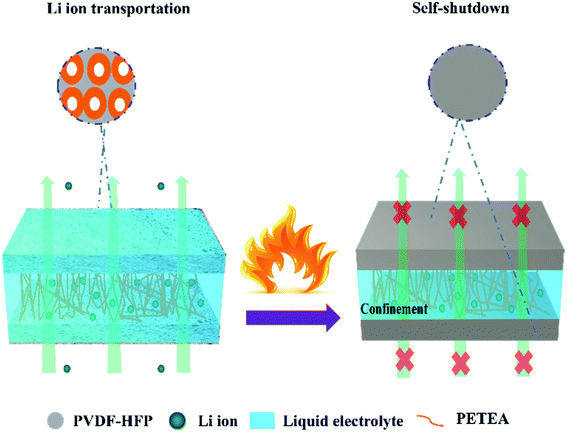
According to these analyses, we propose the mechanism of the thermal response of SGPE-40 to avoid thermal runaway when temperature rises. At room temperature, the sandwich structure of SGPE-40 can absorb a large amount of liquid electrolyte, ensuring good ionic conductivity and cycling performance. The suitable surface pore size can not only ensure the rapid migration of lithium ions and inhibit dendrite growth, but also guarantee safe cycling of Li metal batteries. When the temperature increased, all pores on the surface disappear simultaneously and cut off the battery operation. In this case, the SGPE-40 serves as an effective storage device for the electrolyte at high temperature, avoiding the combustion of the electrolyte, and stabilizing the whole battery. Moreover, the thermal unstability of the PVDF-HFP@SiO2 membrane is no longer a disadvantage, but it is used as a temperature response device to improve the safety of the overall electrolyte,53 which is illustrated in Fig. 6.
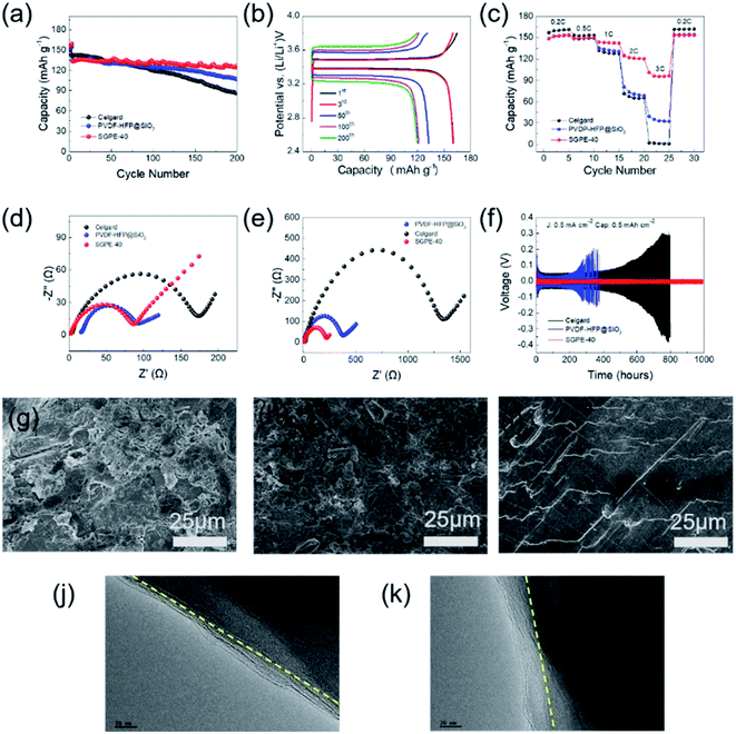
This strategy of utilizing electrolyte's own structural design to achieve self-shutdown function does not obstruct the overall performance of the battery. LFP/Li batteries were assembled to demonstrate the application of the SGPE-40 in lithium metal battery. The cycling performances of the LFP/Li cells using SGPE-40, PVDF-HFP@SiO2 and Celgard 2400 were characterized by galvanostatic charge/discharge measurements at 1C (Fig. 7a) and 2C (Fig. S7†). The cells using three kinds of electrolyte membranes deliver similar discharge capacities in the initial cycles. The discharge capacity of the battery using SGPE-40 remain 95.4% after 200 cycles. Conversely, those batteries using Celgard 2400 and PVDF-HFP@SiO2 couldn't stable charge/discharge after 70 cycles and display significant capacities fading since then, remain 60.8% and 72.3% after 200 cycles, respectively. Fig. 7c shows the rate performance of the battery using SGPE-40, PVDF-HFP@SiO2 and Celgard 2400 at 25 °C. LFP/Li battery using SGPE-40 shows the satisfactory specific capacities of 151.6, 149.2, 143.8, 121.9 and 96.2 mA h g−1 at rates of 0.2C, 0.5C, 1.0C, 2.0C and 3.0C, respectively, remaining original specific capacity (153.3 mA h g−1) when get back to 0.2C. However, battery using PVDF-HFP@SiO2 shows much lower specific capacities of 153.4, 148.6, 135.8, 80.6, 39.5 mA h g−1 at the same rates, losing 63.2% specific capacities than that of SGPE-40 at 3C. Celgard film showed the worst rate performance. The typical charge–discharge profiles of LFP/Li battery using SGPE-40 in a voltage of 2.5–3.9 V at different cycle are shown in Fig. 7b. Obvious potential plateaus are observed when the current rate changed. The values of over-potentials increase along with the increase of the charge/discharge current rates, which is commensurate with the performances of cycling. In addition, as shown in Fig. 7d and e, it can be found that the cell using SGPE-40 and PVDF-HFP@SiO2 have lower impedance than that of the Celgard before cycling. After two hundred cycles (Fig. 7e), the SGPE-40 cell still maintains a low impedance (240 Ω). However, the impedance of the PVDF-HFP@SiO2 and Celgard cells become very large (472 Ω and 1354 Ω, respectively).
Furthermore, in order to further prove the good compatibility of the SGPE to the cathode material, we choose NCA622 cathode to experiment, which is a promising material for high energy density LMBs for its high theoretical capacity and operating voltage.54,55 As shown in Fig. S8a–c,† the NCA622 cells using SGPE-40 deliver high discharge capacities in the active process in the first at the current rate of 0.1C and also deliver stable discharge capacities of 149.2 mA h g−1 at 25 °C. After 100 cycles at the rate of 0.5C, the capacity retention is 87.1%. For the rate performance, the NCA622/Li battery using SGPE-40 delivery specific capacities of 160.2, 156,1, 151.7, 143.5, 136.9 and 119.6 mA h g−1 at rates of 0.1C, 0.2C, 0.3C, 0.4C, 0.5C and 1C, respectively, remaining original specific capacity (158.7 mA h g−1) when get back to 0.1C. This excellent performance can be attributed to the unique sandwich structure electrolyte which can not only effectively transport lithium ions but also inhibit dendrite growth. These demonstrate that the SGPE-40 shows promising potential application for high-performance power rechargeable lithium metal batteries.
To further investigate the compatibility and electrodeposition behavior of the SGPE-40 in Li anode, Li symmetric cells were assembled. As shown in Fig. 7f, the SGPE-40 delivered long-term cycle stability over 1000 h under 0.5 mA cm−2. The near-constant overpotential was as low as around 15 mV. In contrast, the overpotential of Celgard was initially maintained at about 53 mV for 250 h and gradually increased to over 100 mV after 200 h. The voltage hysteresis resulted from the continuous consumption of liquid electrolyte, Li dendrite growth and continuous interface side reactions.56 For the case of PVDF-HFP@SiO2, due to the excessively large pore size, which could not effectively inhibit the growth of dendrites, occurs short circuit after 300 hours. Therefore, the Li/Li cell with SGPE-40 present more stable polarization potential than that of Celgard 2400 or PVDF-HFP@SiO2, suggesting this sandwich structure can decrease the polarization of Li stripping and deposition. Different current density (0.3, 0.5 and 0.7 mA cm−2) was further used to test the plating/striping behavior of the SGPE-40. Compared with the low current density state, the polarization voltage has increased from around 48 mV to around 81 mV, but the Li/Li cell with SGPE-40 also can stable cycle for over 130 h, as shown in Fig. S9,† indicating that SGPE-40 can effectively inhibit the growth of dendrites and promote the uniform deposition of lithium ions, which may be due to the synergy effect of adding the fillers and adjusting the pore size.57 Different Li anodes after cycling in LFP/Li batteries using Celgard, PVDF-HFP@SiO2, and SGPE-40 were measured by SEM, as shown in Fig. 7g–i. Dense and smooth lithium deposition are realized in SGPE-40 caused by its porous structure with smaller pore size.58,59 However, for the other cases, large and thick lithium moss or dendrites were observed on the Li anode surface, which not only cause the loss of the charge–discharge specific capacity of the battery, but also cause short-circuit, thermal runaway and other dangers. After cycling tests, the surface of the SGPE-40 membrane becomes relatively rough (Fig. S10†) compared with the initial state. It may be attributed to the side reaction between Li metal and C–F group in PVDF-HFP.60 Additionally, the TEM images shows that SGPE-40 (Fig. 7k) can form a uniform cathode solid interphase (CEI) on the LiFePO4 material and its thickness is about 20 nm, while PVDF-HFP@SiO2 cannot (Fig. 7j). Those results further exhibits that the SGPE-40 is a practical approach to high safety and high performance LMBs.
4. Conclusion
In this paper, we show a sandwich gel electrolyte structure design, which realizes thermosensitive features and effective self-shutdown via hierarchical structure design without flame retardant components. Furthermore, this kind of porous structured electrolyte without flame retardant additives can ensure the battery has good electrochemical performance, and at the same time achieves good electrode compatibility. This novel designed sandwich gel electrolyte exhibits good flame retardancy, geometric stability and effective self-shutdown characteristics. Safe batteries with this SGPE shows high battery performance at ambient temperature and self-shutdown under high temperature, because the pores will be closed beyond a given threshold. Compared with previous work, our design provides a reliable, fast, inexpensive strategy that can achieve high performance and high safety electrolytes. We believe that this well-design electrolyte has great potential for the practical application in advanced LMBs.Author contributions
Binxuan Xie: data curation, investigation, methodology, writing – original draft. Yong Chen: writing – reviewing & editing. Shimou Chen: conceptualization, supervision, project administration, methodology, investigation. Lili Liu: conceptualization, supervision, project administration, methodology, investigation.Conflicts of interest
There are no conflicts to declare.Acknowledgements
This work was supported financially by National Natural Science Foundation of China (Grant No. 51922099, 21890760), Innovation Academy for Light-duty Gas Turbine, Chinese Academy of Sciences (Grant No. CXYJJ20-MS-05), Natural Science Foundation of Hebei Province for Distinguished Young Scholars (E2020103052) and School Level Cultivation Fund of Beijing Technology and Business University for Distinguished and Excellent Young Scholars. Sincerely appreciate Prof. Suojiang Zhang (IPE, CAS) for his careful academic guidence and great support.References
- M. A. a. J.-M. Tarascon, Nature, 2008, 451, 652–657 CrossRef PubMed.
- K. Xu, Chem. Rev., 2014, 114, 11503–11618 CrossRef CAS PubMed.
- D. Lin, Y. Liu and Y. Cui, Nat. Nanotechnol., 2017, 12, 194–206 CrossRef CAS PubMed.
- C. Yang, K. Fu, Y. Zhang, E. Hitz and L. Hu, Adv. Mater., 2017, 29, 1701169 CrossRef PubMed.
- D. Lu, Y. Shao, T. Lozano, W. D. Bennett, G. L. Graff, B. Polzin, J. Zhang, M. H. Engelhard, N. T. Saenz, W. A. Henderson, P. Bhattacharya, J. Liu and J. Xiao, Adv. Energy Mater., 2015, 5, 1400993 CrossRef.
- B. Huang, Y. Zhang, M. Que, Y. Xiao, Y. Jiang, K. Yuan and Y. Chen, RSC Adv., 2017, 7, 54391–54398 RSC.
- W. Xu, J. Wang, F. Ding, X. Chen, E. Nasybulin, Y. Zhang and J.-G. Zhang, Energy Environ. Sci., 2014, 7, 513–537 RSC.
- H. Xiang, P. Shi, P. Bhattacharya, X. Chen, D. Mei, M. E. Bowden, J. Zheng, J.-G. Zhang and W. Xu, J. Power Sources, 2016, 318, 170–177 CrossRef CAS.
- W. Xue, Z. Shi, M. Huang, S. Feng, C. Wang, F. Wang, J. Lopez, B. Qiao, G. Xu, W. Zhang, Y. Dong, R. Gao, Y. Shao-Horn, J. A. Johnson and J. Li, Energy Environ. Sci., 2020, 13, 212–220 RSC.
- D. Wang, H. Liu, M. Li, D. Xia, J. Holoubek, Z. Deng, M. Yu, J. Tian, Z. Shan, S. P. Ong, P. Liu and Z. Chen, Nano Energy, 2020, 75, 104889 CrossRef CAS.
- G. Zheng, Y. Xiang, S. Chen, S. Ganapathy, T. W. Verhallen, M. Liu, G. Zhong, J. Zhu, X. Han, W. Wang, W. Zhao, M. Wagemaker and Y. Yang, Energy Storage Mater., 2020, 29, 377–385 CrossRef.
- J. Zheng, M. H. Engelhard, D. Mei, S. Jiao, B. J. Polzin, J.-G. Zhang and W. Xu, Nat. Energy, 2017, 2, 1–8 Search PubMed.
- J. Bao, G. Shi, C. Tao, C. Wang, C. Zhu, L. Cheng, G. Qian and C. Chen, J. Power Sources, 2018, 389, 84–92 CrossRef CAS.
- C. M. Costa, Y.-H. Lee, J.-H. Kim, S.-Y. Lee and S. Lanceros-Méndez, Energy Storage Mater., 2019, 22, 346–375 CrossRef.
- A. Manthiram, X. Yu and S. Wang, Nat. Rev. Mater., 2017, 2, 1–16 Search PubMed.
- X. Wu, K. Pan, M. Jia, Y. Ren, H. He, L. Zhang and S. Zhang, Green Energy Environ., 2019, 4, 360–374 CrossRef.
- Y. Zhang, Y. Shi, X. C. Hu, W. P. Wang, R. Wen, S. Xin and Y. G. Guo, Adv. Energy Mater., 2019, 10, 1903325 CrossRef.
- S. Xia, X. Wu, Z. Zhang, Y. Cui and W. Liu, Chem, 2019, 5, 753–785 CAS.
- S. Chen, K. Wen, J. Fan, Y. Bando and D. Golberg, J. Mater. Chem. A, 2018, 6, 11631–11663 RSC.
- Y. Chen, K. Wen, T. Chen, X. Zhang, M. Armand and S. Chen, Energy Storage Mater., 2020, 31, 401–433 CrossRef.
- K. Pan, L. Zhang, W. Qian, X. Wu, K. Dong, H. Zhang and S. Zhang, Adv. Mater., 2020, 32, e2000399 CrossRef PubMed.
- K. Leš and C.-S. Jordan, RSC Adv., 2020, 10, 41296–41304 RSC.
- H. Wu, Y. Cao, H. Su and C. Wang, Angew. Chem., Int. Ed., 2018, 57, 1361–1365 CrossRef CAS PubMed.
- A. L. Ahmad, U. R. Farooqui and N. A. Hamid, RSC Adv., 2018, 8, 25725–25733 RSC.
- W. Ren, Y. Huang, X. Xu, B. Liu, S. Li, C. Luo, X. Li, M. Wang and H. Cao, J. Mater. Sci., 2020, 55, 12249–12263 CrossRef CAS.
- X. Peng, Y. Zhu, S. Song, X. Zhang and Y. Xiang, J. Power Sources, 2020, 455, 227963 CrossRef CAS.
- Z. Chen, P.-C. Hsu, J. Lopez, Y. Li, J. W. F. To, N. Liu, C. Wang, S. C. Andrews, J. Liu, Y. Cui and Z. Bao, Nat. Energy, 2016, 1, 1–8 Search PubMed.
- W. Ji, F. Wang, D. Liu, J. Qian, Y. Cao, Z. Chen, H. Yang and X. Ai, J. Mater. Chem. A, 2016, 4, 11239–11246 RSC.
- L. Wen, J. Liang, J. Chen, Z. Y. Chu, H. M. Cheng and F. Li, Small Methods, 2019, 3, 1900323 CrossRef CAS.
- H. Yang, W. R. Leow and X. Chen, Adv. Mater., 2018, 30, 1704347 CrossRef PubMed.
- K. Liu, W. Liu, Y. Qiu, B. Kong, Y. Sun, Z. Chen, D. Zhuo, D. Lin and Y. Cui, Sci. Adv., 2017, 3, 1601978 CrossRef PubMed.
- J. Zhou, T. Qian, J. Liu, M. Wang, L. Zhang and C. Yan, Nano Lett., 2019, 19, 3066–3073 CrossRef CAS PubMed.
- Q. Zhou, S. Dong, Z. Lv, G. Xu, L. Huang, Q. Wang, Z. Cui and G. Cui, Adv. Energy Mater., 2019, 10, 1903441 CrossRef.
- A. V. Le, M. Wang, D. J. Noelle, Y. Shi and Y. Qiao, J. Appl. Polym. Sci., 2018, 135, 45737 CrossRef.
- M. Baginska, B. J. Blaiszik, R. J. Merriman, N. R. Sottos, J. S. Moore and S. R. White, Adv. Energy Mater., 2012, 2, 583–590 CrossRef CAS.
- J. Qin, H. Peng, J. Huang, X. Zhang, L. Kong, J. Xie, M. Zhao, R. Liu, H. Zhao and Q. Zhang, Small Methods, 2018, 2, 1800100 CrossRef.
- G. Zhang, Z. Zhang, H. Peng, J. Huang and Q. Zhang, Small Methods, 2017, 1, 1700134 CrossRef.
- H. Guo, H. Sun, Z. Jiang, J. Hu, C. Luo, M. Gao, J. Cheng, W. Shi, H. Zhou and S. Sun, ACS Appl. Mater. Interfaces, 2019, 11, 46783–46791 CrossRef CAS.
- Z. Zhao, Y. Huang, F. Qiu, W. Ren, C. Zou, X. Li, M. Wang and Y. Lin, J. Mater. Sci., 2021, 56, 11027–11043 CrossRef CAS.
- W. Ren, C. Ding, X. Fu and Y. Huang, Energy Storage Mater., 2021, 34, 515–535 CrossRef.
- M. Liu, D. Zhou, Y. He, Y. Fu, X. Qin, C. Miao, H. Du, B. Li, Q. Yang, Z. Lin, T. Zhao and F. Kang, Nano Energy, 2016, 22, 278–289 CrossRef CAS.
- D. Zhou, A. Tkacheva, X. Tang, B. Sun, D. Shanmukaraj, P. Li, F. Zhang, M. Armand and G. Wang, Angew. Chem., Int. Ed., 2019, 58, 6001–6006 CrossRef CAS PubMed.
- P. Jaumaux, Q. Liu, D. Zhou, X. Xu, T. Wang, Y. Wang, F. Kang, B. Li and G. Wang, Angew. Chem., Int. Ed., 2020, 59, 9134–9142 CrossRef CAS PubMed.
- B. Liu, Y. Huang, L. Zhao, Y. Huang, A. Song, Y. Lin, M. Wang, X. Li and H. Cao, J. Membr. Sci., 2018, 564, 62–72 CrossRef CAS.
- B. Liu, Y. Huang, H. Cao, L. Zhao, Y. Huang, A. Song, Y. Lin, X. Li and M. Wang, J. Membr. Sci., 2018, 545, 140–149 CrossRef CAS.
- K. Wen, Y. Wang, S. Chen, X. Wang, S. Zhang and L. A. Archer, ACS Appl. Mater. Interfaces, 2018, 10, 20412–20421 CrossRef CAS PubMed.
- H. Ha, E. Kil, Y. Kwon, J. Kim, C. Lee and S. Lee, Energy Environ. Sci., 2012, 5, 6491 RSC.
- D. Zhou, L. Fan, H. Fan and Q. Shi, Electrochim. Acta, 2013, 89, 334–338 CrossRef CAS.
- Y. Liang, Y. Xia, S. Zhang, X. Wang, X. Xia, C. Gu, J. Wu and J. Tu, Electrochim. Acta, 2019, 296, 1064–1069 CrossRef CAS.
- S. Ali, C. Tan, M. Waqas, W. Lv, Z. Wei, S. Wu, B. Boateng, J. Liu, J. Ahmed, J. Xiong, J. B. Goodenough and W. He, Adv. Mater. Interfaces, 2018, 5, 1701147 CrossRef.
- P. Martins, A. C. Lopes and S. Lanceros-Mendez, Prog. Polym. Sci., 2014, 39, 683–706 CrossRef CAS.
- X. Shi, Q. Sun, B. Boateng, Y. Niu, Y. Han, W. Lv and W. He, J. Power Sources, 2019, 414, 225–232 CrossRef CAS.
- B. Xiong, R. Chen, F. Zeng, J. Kang and Y. Men, J. Membr. Sci., 2018, 545, 213–220 CrossRef CAS.
- S. Gu, Y. Cui, K. Wen, S. Chen and J. Zhao, J. Alloys Compd., 2020, 829, 154491 CrossRef CAS.
- J. Zhang, F. Wu, X. Dai, Y. Mai and Y. Gu, J. Alloys Compd., 2021, 858, 158325 CrossRef CAS.
- G. Bieker, M. Winter and P. Bieker, Phys. Chem. Chem. Phys., 2015, 17, 8670–8679 RSC.
- D. Lin, P. Y. Yuen, Y. Liu, W. Liu, N. Liu, R. H. Dauskardt and Y. Cui, Adv. Mater., 2018, 30, e1802661 CrossRef PubMed.
- S. Choudhury, D. Vu, A. Warren, M. D. Tikekar, Z. Tu and L. A. Archer, Proc. Natl. Acad. Sci. U. S. A., 2018, 115, 6620–6625 CrossRef CAS PubMed.
- M. D. Tikekar, L. A. Archer and D. L. Koch, J. Electrochem. Soc., 2014, 161, A847–A855 CrossRef CAS.
- W. Zhang, J. Nie, F. Li, Z. L. Wang and C. Sun, Nano Energy, 2018, 45, 413–419 CrossRef CAS.
Footnote |
| † Electronic supplementary information (ESI) available. See DOI: 10.1039/d1ra02641k |
| This journal is © The Royal Society of Chemistry 2021 |

