 Open Access Article
High-throughput immunosensor chip coupled with a fluorescent DNA dendrimer for ultrasensitive detection of cardiac troponin T†
Ruike Wang‡
ab,
Chen Zong‡b,
Gairu Lia,
Junhong Wangc,
Tiantian Kong*d,
Fei Li*ab and
Junmin Chang *a
*a
aCollege of Pharmacy, Xinjiang Medical University, Urumqi, 830011, P. R. China. E-mail: cjmcjn2471@sohu.com
bState Key Laboratory of Natural Medicines, China Pharmaceutical University, Nanjing, 210009, P. R. China
cJiangsu Province Hospital, Nanjing Medical University First Affiliated Hospital, Nanjing, 210029, P. R. China
dXinjiang Medical University Affiliated Second Hospital, Urumqi, 830063, P. R. China
First published on 13th August 2021
Abstract
A novel fluorescence (FL) imaging platform was established for ultrasensitive and rapid detection of cardiac troponin T (cTnT), based on a high-throughput immunosensor chip and a DNA dendrimer capped with a large number of fluorescent dyes (FDD@Cy5). Through an enzyme-free and step-by-step strategy, FDD@Cy5 was self-assembled facilely. After the formation of a sandwich immunocomplex and biotin–streptavidin conjugation, FDD@Cy5 could be captured on the chip. FL signals emerged from Cy5 under external light and the enrichment of Cy5 on the dendrimer led to signal amplification. A FL image containing 90 spots could be collected instantaneously by laser confocal scanning microscopy and the brightness of all the spots corresponded to the concentrations of target cTnT. Under optimal conditions, the immunosensor chip coupled with FDD@Cy5 exhibited an excellent detection limit of 0.10 pg L−1, a wide linear range from 0.20 pg L−1 to 2.0 ng L−1, a sample consumption down to 3.0 μL and a maximum throughput of 45 tests per h. The proposed approach was also applied to cTnT quantitation in serum samples with acceptable accuracy, providing a new avenue for early diagnosis and the prognosis evaluation of acute myocardial infarction.
1. Introduction
Acute myocardial infarction (AMI) is one of the leading causes of death and disease worldwide.1 Early screening, evaluation and monitoring of AMI is of great significance for improving the survival rate of patients.2 Among AMI-related serum markers, cardiac troponin (cTnT) has been recognized as the analyte of choice for decades.3–5 However, at the early stage of AMI, cTnT often exists in trace amounts, even less than interfering substances, making it difficult to detect.6 Considering that AMI and its complications may be life-threatening, it is insensitive to let patients wait for the test report for a long time. It is imperative to develop convenient platforms for ultrasensitive, accurate and rapid quantitation of cTnT.7Immunosensor chip-based optical imaging platforms show potential in the specific and high-throughput detection of biomarkers, which employs principles of immunoreaction to recognize the target and utilizes spatial resolution strategy to distinguish the optical signals from different sensing sites on the array simultaneously.8–10 Compared with traditional analytical methods such as enzyme-linked immunosorbent assay and chromatography,11–13 it possesses several advantages including easy operation, intuitive testing and the capacity of performing parallel real-time detection for a large number of samples. In our previous work, immunosensor chip always contained 48 sensing sites (diameter of each site: 4 mm),14,15 on which a maximum of 48 samples could be detected in a single analysis process. In this work, an improved immunosensor chip was designed by immobilizing capture antibody (Ab1) of cTnT in 90 sensing sites (diameter of each site: 2.7 mm) on the same disposable glass (Scheme 1). Reducing the region of each site is an endless pursuit for immunoassay of biomarkers, which is beneficial to saving of samples and testing time, and promotion of analytical throughput.
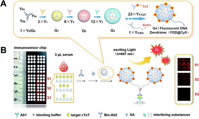 | ||
| Scheme 1 (A) Schematic diagram of procedure of FDD@Cy5. (B) The immunosensor chip with 90 sensing sites and schematic diagram of the process of ultrasensitive FL immunoassay of cTnT. | ||
Besides, enhancing the ability of signal probe is also the assiduously goal, which is favourable for improving detection sensitivity. To obtain amplified signal, nanomaterials which can carry plenty of signal indicators are always resorted to.14,16–18 For instance, Wang et al. reported a colorimetric method for myoglobin detection based on a single Au nanoparticle loaded with hundreds of hemin/G-quadruplex DNAzymes. Due to the AuNPs amplification, this assay showed a detection limit as low as 2.5 nM.17 Recently, assembled DNA nanostructures have attracted great interests due to the high loading ability, good biological properties, easy preparation process and great potential for functional modification.19–23 As a typical self-assembled DNA material, DNA dendrimer has been used as signal amplifiers to construct electrochemiluminescence (ECL) and chemiluminescence (CL) biosensors.24,25 Herein, a fluorescent DNA dendrimer (FDD@Cy5) was prepared and combined with the immunosensor chip to develop a novel FL imaging platform for ultrasensitive and fast detection of cTnT.
As shown in Scheme 1A, the DNA dendrimer was prepared facilely through an enzyme-free and step-by-step assembly of different Y-shaped DNAs. Y-shaped DNA labelled with biotin (Y4-Bio) was designed to link the dendrimer to sandwich immunocomplex, while Y-shaped DNA labelled with Cy5 (Y4-Cy5) was designed as the FL indicator. The ratio of Y4-Cy5 to Y4-Bio was set as 23![[thin space (1/6-em)]](https://www.rsc.org/images/entities/char_2009.gif) :
:![[thin space (1/6-em)]](https://www.rsc.org/images/entities/char_2009.gif) 1 to realize the signal amplification. As displayed in Scheme 1B, after the sandwich immunoreaction and biotin-streptavidin (SA) recognition, the FDD@Cy5 was captured on the immunosensor chip. The more cTnT the samples contained, the more FL dyes kept on the sensing sites 90 FL spots corresponding to 90 different cTnT samples could be instantaneously observed by a laser confocal scanning microscopy (LCSM). The brightness of the spots increased with increasing concentrations of target cTnT. The proposed FL imaging platform provided excellent performance for trace detection of cTnT, implying the great potential for early diagnosis and the prognosis evaluation of AMI.
1 to realize the signal amplification. As displayed in Scheme 1B, after the sandwich immunoreaction and biotin-streptavidin (SA) recognition, the FDD@Cy5 was captured on the immunosensor chip. The more cTnT the samples contained, the more FL dyes kept on the sensing sites 90 FL spots corresponding to 90 different cTnT samples could be instantaneously observed by a laser confocal scanning microscopy (LCSM). The brightness of the spots increased with increasing concentrations of target cTnT. The proposed FL imaging platform provided excellent performance for trace detection of cTnT, implying the great potential for early diagnosis and the prognosis evaluation of AMI.
2. Materials and methods
2.1 Reagents and apparatus
Glass chips modified with aromatic aldehyde group were purchased from Ruimai Biotechnology Co., Ltd. (Shanghai, China). All the oligonucleotides were synthesized and purified by Sangon Biotechnology Co., Ltd. (Shanghai, China) and the sequences were listed in Table S1.† SA was also from Sangon Biotechnology Co., Ltd. (Shanghai, China). The Ab1 and biotin-antibody2 (Bio-Ab2) of cTnT (CT11N102 and CT11B101), standard solution of cTnT (CT01N301) were from KeyBiotech Co., Ltd. (Beijing, China). Standard solutions of alpha fetoprotein (AFP), carcinoembryonic antigen (CEA) and thyroid-stimulating hormone (TSH) were from Autobio Diagnostics Co., Ltd. (Zhengzhou, Henan, China). BlockPRO™ protein-free blocking buffer was from MineBio Life Sciences Ltd. (Shanghai, China). The clinical serum samples were from the First Affiliated Hospital with Nanjing Medical University and approval of ethical committee was obtained for this study. Ultrapure water used in the whole experiments was from a water purification system (≥ 18 MΩ cm, Millipore, Milford, MA, USA). Immunoreaction buffer was 0.01 M phosphate buffered saline (PBS) (pH 7.4). Washing buffer was 0.01 M PBS (pH 7.4) spiked with 0.05% Tween-20. TE buffer (pH 8.0) was used to dissolve and dilute all the oligonucleotides. All other reagents were of analytical grade and used without further purification.Scanning electron micrographs of glass chip before and after modification were obtained with a 3400N II scanning electron microscope (SEM) (JEOL Ltd., Tokyo, Japan). Elemental analysis spectra of immunosensor chip before and after modification were measured with X-ray photoelectron spectroscopy (XPS) on a PHI-5000 VersaProbe (Ulvac-Phi Ltd., Tokyo, Japan). The size and morphology of FDD@Cy5 was characterized by a JEM-2100 transmission electron microscope (TEM) (JEOL Ltd., Tokyo, Japan). Atomic force microscope (AFM) images of FDD@Cy5 were obtained by a Bruker Dimension Icon atomic force microscope (Bruker Co., Billerica, MA, USA) and the data analysis was performed on Nanoscope Analysis 1.7 software. The ultraviolet-visible (UV-vis) absorption spectra of Cy5, DNA dendrimer and FDD@Cy5 were recorded with a Nano-100 micro spectrophotometer (Allsheng Instruments Co., Ltd., Hangzhou, Zhejiang, China). FL spectra of sDNA-Cy5 and FDD@Cy5, and the FL emission of FDD@Cy5 distributed in different wavelengths were measured using FLS 1000 steady/transient fluorescence spectrometer (Edinburgh Instruments, UK). The FL signals from the sensing sites of the immunosensor chip were obtained by a FV3000 laser confocal scanning microscope (LCSM) (Olympus Co., Ltd., Tokyo, Japan) with an objective lens (1.25×) while the visual region of single imaging was 10 mm × 10 mm. ECL immunoassay for reference detection of cTnT was carried out on an Elecsys 2010 System (Roche Diagnostics GmbH, Mannheim, Baden-Württemberg, Germany).
2.2 Design and fabrication of immunosensor chip
A layer of photo-inactive film with 90 holes (2.7 mm diameter) in a (3 × 3) × 10 format was designed and pasted on the glass chip manually. All the glass was covered but left 90 plots uncovered, which constituted reservoirs to accommodate solutions for immunoassay.Then, 3μL of Ab1 of cTnT at 20 μg mL−1 was dropped in each sensing site and incubated overnight at 4 °C. The immobilization of Ab1 could be achieved efficiently through the interaction between amino groups of antibody and aromatic aldehydes on the glass. After washing and drying, 3 μL of blocking buffer was dropped in each site for 1 h to block the unreacted aldehyde groups. After washing and drying, the immunosensor chip was obtained and stored in 0.01 M pH 7.4 PBS at 4 °C before use.
2.3 Preparation of FDD@Cy5
FDD@Cy5 was self-assembled from different Y-shaped DNAs (Y-DNA) (Scheme 1A). Y-DNA called Y0 or G0 was prepared by mixing equal moles of 3 single strands (the concentration of each strand was 100 μM): Y0a, Y0b and Y0c. Other Y-DNAs (Y1, Y2, Y3, Y4-Cy5 and Y4-Bio) were prepared according to similar procedure. Each Y-DNA was parallelly incubated at 25 °C for 1 h. The final concentration of each Y-DNA was 33 μM.Then, different generations of DNA dendrimer (Gn) were prepared. G1 was synthesized by mixing G0 and Y1 at a ratio of 1![[thin space (1/6-em)]](https://www.rsc.org/images/entities/char_2009.gif) :
:![[thin space (1/6-em)]](https://www.rsc.org/images/entities/char_2009.gif) 3. G2 was synthesized by mixing G1 and Y2 at a ratio of 1
3. G2 was synthesized by mixing G1 and Y2 at a ratio of 1![[thin space (1/6-em)]](https://www.rsc.org/images/entities/char_2009.gif) :
:![[thin space (1/6-em)]](https://www.rsc.org/images/entities/char_2009.gif) 6. G3 was prepared using G2 and Y3 at a ratio of 1
6. G3 was prepared using G2 and Y3 at a ratio of 1![[thin space (1/6-em)]](https://www.rsc.org/images/entities/char_2009.gif) :
:![[thin space (1/6-em)]](https://www.rsc.org/images/entities/char_2009.gif) 12. Theoretically, G4 was synthesized using Y4-Cy5 and G3 at a ratio of 24
12. Theoretically, G4 was synthesized using Y4-Cy5 and G3 at a ratio of 24![[thin space (1/6-em)]](https://www.rsc.org/images/entities/char_2009.gif) :
:![[thin space (1/6-em)]](https://www.rsc.org/images/entities/char_2009.gif) 1 for signal amplification, however, in this study, G4 required to be captured on the immunosensor chip to form a sandwich immunocomplex by biotin-streptomavidin conjugation. Therefore, Y4-Cy5 (Y4a + Y4b + Y4c-Cy5) and Y4-Bio (Y4a + Y4b + Y4c-Bio) were simultaneously linked with G3 at a ratio of 23
1 for signal amplification, however, in this study, G4 required to be captured on the immunosensor chip to form a sandwich immunocomplex by biotin-streptomavidin conjugation. Therefore, Y4-Cy5 (Y4a + Y4b + Y4c-Cy5) and Y4-Bio (Y4a + Y4b + Y4c-Bio) were simultaneously linked with G3 at a ratio of 23![[thin space (1/6-em)]](https://www.rsc.org/images/entities/char_2009.gif) :
:![[thin space (1/6-em)]](https://www.rsc.org/images/entities/char_2009.gif) 1
1![[thin space (1/6-em)]](https://www.rsc.org/images/entities/char_2009.gif) :
:![[thin space (1/6-em)]](https://www.rsc.org/images/entities/char_2009.gif) 1. Each generation was incubated at 25 °C for 1 h. The final concentration of as prepared fluorescent DNA dendrimer (FDD@Cy5) was 0.72 μM.
1. Each generation was incubated at 25 °C for 1 h. The final concentration of as prepared fluorescent DNA dendrimer (FDD@Cy5) was 0.72 μM.
2.4 FL imaging immunoassy
To obtain the calibration plot of cTnT, 3.0 μL of the standard solution diluted with 0.01 M PBS (pH 7.4) to different concentrations were delivered into different sensing sites and incubated for 30 min, followed by washing and drying. Then 3.0 μL of corresponding Bio-Ab2 (1.0 μg mL−1) was injected and incubated for 30 min. After washing and drying, 3.0 μL of SA (1.0 μg mL−1) was added to bind Bio-Ab2 and incubated for another 30 min, followed by washing and drying. Finally, 3.0 μL of FDD@Cy5 was added into the sensing sites for 30 min, followed by washing and drying. To implement the detection of cTnT in clinical serum samples, 3.0 μL of serum sample was added to the sensing sites to perform the same procedures.FL signals from the sensing sites of the immunosensor chip were recorded by a LCSM. To demonstrate the reliability and reproducibility of the proposed FL biosensing chip, every 3 × 3 array was used as a visual field for the same sample, which meant the number of experiments was 9 (Scheme 1B). Spots were converted to digital values by the use of ImageJ software. The FL intensity of each spot was calculated as the mean pixel intensity within a circle of a given radius around each spot centre.
3. Results and discussion
3.1 Characterization of immunosensor chip
The modification of Ab1 on the immunosensor chip was characterized by SEM. As shown in Fig. 1A, the surface of original glass chip was smooth and homogeneous. Upon immobilization of Ab1, obvious aggregated biomolecules could be observed on the glass chip (Fig. 1B), indicating the successful coverage of Ab1 on the surface of chip. XPS analysis was further performed. As shown in Fig. 1, compared with the original glass chip (Fig. 1C, blue curve), Ab1 modified glass chip (Fig. 1D, red curve) displayed a new N 1s peak, which belonged to Ab1, indicating the successful fabrication of Ab1 on the immunosensor chip.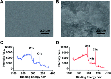 | ||
| Fig. 1 SEM images of the original glass chip (A) and Ab1 modified glass chip (B); elemental analysis of the original glass chip (C, blue curve) and Ab1 modified glass chip (D, red curve). | ||
3.2 Characterization of DNA dendrimer
The formation of G0, G1, G2, G3 and G4 DNA dendrimer was verified by agarose gel electrophoresis analysis. As shown in Fig. 2A, the electrophoretic mobility of DNA dendrimers decreased with the increasing generations, consistently with previous reports.26–28 As-prepared DNA dendrimers without any purification showed only a single band, demonstrating that no by-product was formed in the assembly procedure, confirming the efficiency of the self-assembly strategy. Furthermore, the FDD@Cy5 was characterized by TEM. As shown in Fig. 2B, FDD@Cy5 was spherical with good monodispersity and the size was ∼45 nm. For more accurate representation, the assembly result was characterized by AFM (Fig. 2C). The longitudinal values in AFM result were consistent with that measured by TEM.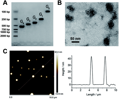 | ||
| Fig. 2 (A) Agarose gel electrophoresis of G0–G4. (B) TEM image of FDD@Cy5. (C) AFM image and analysis of FDD@Cy5. | ||
3.3 Optical property and FL signal amplification of FDD@Cy5
To investigate the optical property of FDD@Cy5, the UV-vis spectra was used to characterize 0.72 μM of DNA dendrimer, Cy5 and FDD@Cy5. As shown in Fig. 3A, for DNA dendrimer, the UV-vis absorption spectrum (Fig. 3A, blue line) exhibited a distinct DNA peak at ∼260 nm. For Cy5, the UV-vis absorption spectrum (Fig. 3A, green line) showed a distinct Cy5 peak at ∼647 nm.29 Both of the two peaks were observed in the UV-vis absorption spectrum for the FDD@Cy5 (Fig. 3A, red line), demonstrating the successful connection of the DNA dendrimer and Cy5 molecules, and implying the best excitation wavelength for FDD@Cy5. FL emission of FDD@Cy5 distributed in different wavelengths also showed that the FL intensity of FDD@Cy5 was the strongest under a ∼650 nm incident light (Fig. 3B).To verify the signal amplification of FDD@Cy5 in FL immunoassay, the FL characteristics of single-strand DNA labelled with Cy5 (sDNA-Cy5) and FDD@Cy5 were studied. Under the same condition, FL signals from sensing sites using 0.14 μM of sDNA-Cy5 and FDD@Cy5 as indicators were compared. As shown in Fig. 3C, FDD@Cy5 triggered approximately 4-fold stronger FL than sDNA-Cy5, suggesting that FDD@Cy5 possessed much better FL ability, which attributed to the large amounts of Cy5 loaded on the DNA dendrimer. Detailed FL spectra analysis could be found in Fig. S1.†
3.4 Optimization of assay conditions
The effect of incubation time on the performance of FL immunoassay was investigated using 0.20 ng L−1 cTnT as a model. As shown in Fig. S2,† the FL intensity raised with the increasing incubation time of cTnT (Fig. S2A†) and FDD@Cy5 (Fig. S2B†), which reached the maximum values at 30 min and 30 min, respectively. Therefore, 30 min and 30 min were selected as the optimized incubation times.Concentrations of the Bio-Ab2, SA and FDD@Cy5 also had critical effects on the performance of FL immunoassay. As displayed in Fig. S3,† the FL intensity generally increased with increasing concentration of Bio-Ab2 (Fig. S3A†), SA (Fig. S3B†) and FDD@Cy5 (Fig. S3C†). By the comprehensive consideration of FL intensity, reagent dosage and accuracy of signal readout, 1.0 μg mL−1 of Bio-Ab2, 1.0 μg mL−1 of SA and 0.14 μM of FDD@Cy5 were chosen as the optimized parameters.
3.5 FL immunoassay of cTnT
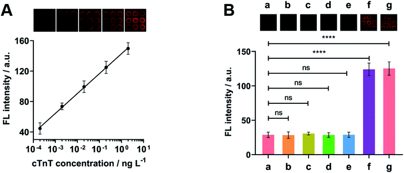
Under optimal experimental conditions, the FL images and the calibration plot for immunoassay of cTnT were obtained. As shown in Fig. 4A, with the increasing concentrations of cTnT, the FL spots on the immunosensor chip became more and more bright. The FL intensity was proportional to the logarithm value of analyte concentration over the range of 2.0 × 10⁻⁴ ng L−1 to 2.0 ng L−1. The calibration plot was Y = 142.89 + 26.14![[thin space (1/6-em)]](https://www.rsc.org/images/entities/char_2009.gif) lg
lg![[thin space (1/6-em)]](https://www.rsc.org/images/entities/char_2009.gif) X (R2 = 0.9991) and the detection limit was estimated to be 0.10 pg L−1 corresponding to the signal of 3 SD, lower than previously reported cTnT quantitation methods (Table S2†).30–35 The whole FL immunoassay strategy could be completed within 2 h and the throughput was calculated to be 45 samples per hour. After 56 days storage of FDD@Cy5 in the dark at 4 °C, the FL intensity remained 91% of the initial response (Fig. S4†), implying excellent stability.
X (R2 = 0.9991) and the detection limit was estimated to be 0.10 pg L−1 corresponding to the signal of 3 SD, lower than previously reported cTnT quantitation methods (Table S2†).30–35 The whole FL immunoassay strategy could be completed within 2 h and the throughput was calculated to be 45 samples per hour. After 56 days storage of FDD@Cy5 in the dark at 4 °C, the FL intensity remained 91% of the initial response (Fig. S4†), implying excellent stability.
3.6 Evaluation of cross-reactivity
The cross-reactivity between cTnT immunosensor and nonspecific analytes was evaluated by comparing the FL intensity after incubation with the blank solution, TSH, CEA, AFP, CA125, cTnT, the mixture of TSH, CEA, AFP, CA125 and target cTnT (all of them were 0.20 ng L−1). As expected, the immunosensor exhibited obvious responses to target cTnT and the mixture containing target (Fig. 4B), indicating good specificity and negligible nonspecific binding.3.7 Detection of cTnT in clinical serum samples
To investigate the analytical reliability and application potential of the FL biosensing method based on FDD@Cy5, the concentrations of cTnT in 30 human serum samples from healthy people and patients (the clinical cutoff values of cTnT was 14 ng L−1) were tested. When the cTnT levels were higher than the calibration range, the serum samples were appropriately diluted with 0.01 M pH 7.4 PBS. The results obtained by proposed method were compared with the reference values measured by commercial ECL methods. As shown in Fig. 5, the correlation coefficients (R2 > 0.99) and the slope close to 1 indicated acceptable accuracy of the proposed assay.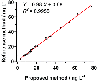 | ||
| Fig. 5 Samples (n = 30) assayed for correlation studies. Results of immunoassay of cTnT in human sera were compared with reference analyte immunoassays. | ||
4. Conclusions
This work reported a highly sensitive and specific FL biosensing approach for detection of cTnT based on an immunosensor chip and a fluorescent DNA dendrimer. By loading plenty of Cy5 molecules on the DNA dendrimer, a 4-fold FL signal amplification could be achieved. The protocol displayed a wide detection range and the limit of detection down to 0.10 pg L−1.90 samples could be tested within 2 h, providing a throughput of 45 tests per h. The immunosensor chip coupled with FDD@Cy5 was available to measure cTnT in clinical serum samples, with high throughput, small consumption, great accuracy, sensitivity and selectivity. Although this study was specific only to cTnT, it could be easily expanded to detection of other protein analytes by changing the antigen and corresponding antibodies, indicating potential application in extensive bioanalysis.Ethical statement
All experiments were performed in accordance with the Guidelines “the Helsinki Declaration of the World Medical Association in 1964 and revised in 2013”, and approved by the ethics committee at “Jiangsu Province Hospital and Nanjing Medical University First Affiliated Hospital”. Informed consents were obtained from human participants of this study.Author contributions
W. R., Z. C. and L. G. conducted the experiments. W. R. and Z. C. wrote the manuscript. K. T., L. F. and C. J. analysed the data and revised the manuscript. W. J. provided the clinical samples and performed ECL experiments for comparison. All authors have given approval to the final version of the manuscript.Conflicts of interest
There are no conflicts to declare.Acknowledgements
This study was supported by the Fundamental Research Funds for the Central Universities (2632021ZD21), National Natural Science Foundation of China (21505160), Natural Science Foundation of Jiangsu Province (BK20150690), Xinjiang Science Fund for Distinguished Young Scholar Project (No. 2018Q003), Postgraduate innovation project of the Autonomous Region (XJ2021G205) and Key Laboratory of Active Components of Xinjiang Natural Medicine and Drug Release Technology (XJDX1713).Notes and references
- S. S. Virani, A. Alonso, E. J. Benjamin, M. S. Bittencourt, C. W. Callaway, A. P. Carson, A. M. Chamberlain, A. R. Chang, S. S. Cheng, F. N. Delling, L. Djousse, M. S. Elkind, J. F. Ferguson, M. Fornage, S. S. Khan, B. M. Kissela, K. L. Knutson, T. W. Kwan, D. T. Lackland, T. T. Lewis, J. H. Lichtman, C. T. Longenecker, M. S. Loop, P. L. Lutsey, S. S. Martin, K. Matsushita, A. E. Moran, M. E. Mussolino, A. M. Perak, W. D. Rosamond, G. A. Roth, U. K. A. Sampson, G. M. Satou, E. B. Schroeder, S. H. Shah, C. M. Shay, N. L. Spartano, A. Stokes, D. L. Tirschwell, L. B. VanWagner and C. W. Tsao, Circulation, 2020, 141, e139–e596 Search PubMed.
- R. Gulati, A. Behfar, J. Narula, A. Kanwar, A. Lerman, L. Cooper and M. Singh, Mayo. Clin. Proc., 2020, 95, 136–156 CrossRef PubMed.
- J. Mair, A. Jaffe, F. Apple and B. Lindahl, Dis. Markers, 2015, 2015, 1–3 CrossRef PubMed.
- A. S. Jaffe, J. Ravkilde, R. Roberts, U. Naslund, F. S. Apple, M. Galvani and H. Katus, Circulation, 2000, 102, 1216–1220 CrossRef CAS PubMed.
- L. Babuin and A. S. Jaffe, Can. Med. Assoc. J., 2005, 173, 1191–1202 CrossRef PubMed.
- S. B. Nimse, M. D. Sonawane, K. S. Song and T. Kim, Analyst, 2016, 141, 740–755 RSC.
- A. P. Nikolova, T. C. Hitzeman, R. Baum, A. M. Caldaruse, S. Agvanian, Y. Xie, D. R. Geft, D. H. Chang, J. D. Moriguchi, A. Hage, B. Azarbal, L. S. Czer, M. M. Kittleson, J. K. Patel, A. H. B. Wu, J. A. Kobashigawa, M. Hamilton, T. T. Hong and R. M. Shaw, JAMA Cardiol, 2018, 3, 1206–1210 CrossRef PubMed.
- Y. H. Zhong, X. Y. Wu, J. Li, Q. C. Lan, Q. L. Jing, L. F. Min, C. L. Ren, X. Y. Hu, A. Lambert, Q. Cheng and Z. J. Yang, Anal. Chim. Acta, 2019, 1049, 213–218 CrossRef CAS PubMed.
- J. Zhang, J. J. Qian, Q. S. Mei, L. Yang, L. F. He, S. J. Liu, C. Zhang and K. Zhang, Biosens. Bioelectron., 2019, 128, 61–67 CrossRef CAS PubMed.
- A. R. Liu, F. Zhao, Y. W. Zhao, L. Shangguan and S. Q. Liu, Biosens. Bioelectron., 2016, 81, 97–102 CrossRef CAS PubMed.
- E. Dobrovolskaia, A. Gam and J. E. Slater, Clin. Exp. Allergy, 2006, 36, 525–530 CrossRef CAS PubMed.
- S. T. Evans, M. Holstein and S. M. Cramer, Anal. Chem., 2011, 83, 4184–4192 CrossRef CAS PubMed.
- T. Y. Huang, L. M. Chi and K. Y. Chien, J. Chromatogr. A, 2018, 1571, 201–212 CrossRef CAS PubMed.
- C. Zong, D. D. Zhang, H. Yang, S. M. Wang, M. Chu and P. Li, Microchim. Acta, 2017, 184, 3197–3204 CrossRef CAS.
- C. Zong, J. Wu, M. M. Liu, L. L. Yang, F. Yan and H. X. Ju, Anal. Chem., 2014, 86, 9939–9944 CrossRef CAS PubMed.
- J. P. Lei and H. X. Ju, Chem. Soc. Rev., 2012, 41, 2122–2134 RSC.
- Q. Wang, X. H. Yang, X. H. Yang, F. Liu and K. M. Wang, Sens. Actuators, B, 2015, 212, 440–445 CrossRef CAS.
- C. C. Fu, S. L. Jin, W. B. Shi, J. Oh, H. Y. Cao and Y. M. Jung, Anal. Chem., 2018, 90, 13159–13162 CrossRef CAS PubMed.
- N. Liu, H. Lu, L. Liu, W. Ni, Q. F. Yao, G. J. Zhang and F. Yang, Anal. Chem., 2021, 93, 5917–5923 CrossRef CAS PubMed.
- J. J. Ge, Y. Zhao, C. L. Li and G. F. Jie, Anal. Chem., 2019, 91, 3546–3554 CrossRef CAS PubMed.
- Q. Jiang, C. Song, J. Nangreave, X. W. Liu, L. Lin, D. L. Qiu, Z. G. Wang, G. Z. Zou, X. J. Liang, H. Yan and B. Q. Ding, J. Am. Chem. Soc., 2012, 134, 13396–13403 CrossRef CAS PubMed.
- S. Bi, B. Xiu, J. Y. Ye and Y. Dong, ACS Appl. Mater. Interfaces, 2015, 7, 23310–23319 CrossRef CAS PubMed.
- Y. Z. Zhang, J. Tu, D. Q. Wang, H. T. Zhu, S. K. Maity, X. M. Qu, B. Bogaert, H. Pei and H. B. Zhang, Adv. Mater., 2018, 30, e1703658 CrossRef PubMed.
- L. Li, C. C. Niu, T. Li, Y. F. Wan, Y. Zhou, H. J. Wang, R. Yuan and P. Liao, Biosens. Bioelectron., 2018, 101, 206–212 CrossRef CAS PubMed.
- S. Bi, S. Y. Hao, L. Li and S. S. Zhang, Chem. Commun., 2010, 46, 6093–6095 RSC.
- H. M. Meng, X. B. Zhang, Y. F. Lv, Z. L. Zhao, N. N. Wang, T. Fu, H. H. Fan, H. Liang, L. P. Qiu, G. Z. Zhu and W. H. Tan, ACS Nano, 2014, 8, 6171–6181 CrossRef CAS PubMed.
- Y. J. Qu, J. J. Yang, P. F. Zhan, S. L. Liu, K. Zhang, Q. Jiang, C. Li and B. Q. Ding, ACS Appl. Mater. Inter., 2017, 9, 20324–20329 CrossRef CAS PubMed.
- H. M. Zhang, Y. L. Ma, Y. Xie, Y. An, Y. S. Huang, Z. Zhu and C. Y. J. Yang, Sci. Rep., 2015, 5, 10099 CrossRef CAS PubMed.
- S. H. Kim, J. R. Gunther and J. A. Katzenellenbogen, Org. lett., 2008, 10, 4931–4934 CrossRef CAS PubMed.
- S. Gogoi and R. Khan, Phys. Chem. Chem. Phys., 2018, 20, 16501–16509 RSC.
- N. Karimian, M. Vagin, M. H. A. Zavar, M. Chamsaz, A. P. Turner and A. Tiwari, Biosens. Bioelectron., 2013, 50, 492–498 CrossRef CAS PubMed.
- B. V. Silva, B. A. Rodríguez, G. F. Sales, M. D. P. T. Sotomayor and R. F Dutra, Biosens. Bioelectron., 2016, 77, 978–985 CrossRef CAS PubMed.
- D. Brondani, J. V. Piovesan, E. Westphal, H. Gallardo, R. A. F. Dutra, A. Spinelli and L. C. Vieira, Analyst, 2014, 139, 5200–5208 RSC.
- M. Pawula, Z. Altintas and I. E. Tothill, Talanta, 2016, 146, 823–830 CrossRef CAS PubMed.
- K. S. Song, S. B. Nimse, M. D. Sonawane, Y. H. Lin, Z. Zhou and T. Kim, Analyst, 2017, 142, 3816–3821 RSC.
Footnotes |
| † Electronic supplementary information (ESI) available. See DOI: 10.1039/d1ra03420k |
| ‡ W. R. and Z. C. contributed equally. |
| This journal is © The Royal Society of Chemistry 2021 |


