 Open Access Article
Epoxy composite with high thermal conductivity by constructing 3D-oriented carbon fiber and BN network structure
Ying Wang†
a,
Yuan Gao† ab,
Bo Tang†a,
Xinfeng Wu
 *a,
Jin Chen*ac,
Liming Shana,
Kai Sun
 a,
Yuantao Zhaoa,
Ke Yangd,
Jinhong Yu
 e and
Wenge Li*a
aMerchant Marine College, College of Ocean Science and Engineering, Shanghai Maritime University, Shanghai 201306, China. E-mail: xfwu@shmtu.edu.cn; wgli@shmtu.edu.cn; jin.chen@sht-tek.com
bPurchasing and Supplying Logistics Center Department, COMAC Shanghai Aircraft Manufacturing Co., Ltd, Shanghai 201324, China
cElectronics Materials and Systems Laboratory, Department of Microtechnology and Nanoscience (MC2), Chalmers University of Technology, SE-412 58 Göteborg, Sweden
dSchool of Materials Science and Engineering, Central South University, Changsha 410083, China
eKey Laboratory of Marine Materials and Related Technologies, Zhejiang Key Laboratory of Marine Materials and Protective Technologies, Ningbo Institute of Materials Technology & Engineering, Chinese Academy of Sciences, Ningbo, 315201, China
First published on 21st July 2021
Abstract
As electronic devices tend to be integrated and high-powered, thermal conductivity is regarded as the crucial parameter of electronic components, which has become the main factor that limits the operating speed and service lifetime of electronic devices. However, constructing continuous thermal conductive paths for low content particle fillers and reducing interface thermal resistance between fillers and matrix are still two challenging issues for the preparation of thermally conductive composites. In this study, 3D-oriented carbon fiber (CF) thermal network structures filled with boron nitride flakes (BN) as thermal conductive bridges were successfully constructed. The epoxy composite was fabricated by thermal conductive material with a 3D oriented structure by the vacuum liquid impregnation method. This special 3D-oriented structure modified by BN (BN/CF) could efficiently broaden the heat conduction pathway and connected adjacent fibers, which leads to the reduction of thermal resistance. The thermal conductivity of the boron nitride/carbon fiber/epoxy resin composite (BN/CF/EP) with 5 vol% 10 mm CF and 40 vol% BN reaches up to 3.1 W m−1 K−1, and its conductivity is only 2.5 × 10⁻⁴ S cm−1. This facile and high-efficient method could provide some useful advice for the thermal management material in the microelectronic field and aerospace industry.
1. Introduction
Nowadays, microelectronic devices have a high demand for high thermal conductive materials to solve the problem of material aging, as micro equipment gradually tends to be energy-intensive and integrated.1–3 At this stage, the polymer-based composites are widely used to conduct research on thermal management composite.4,5 As is well known, polymer materials are accepted in this field mainly due to their good mechanical performance, stable chemical performance and excellent processability.6,7 However, traditional polymer materials have weak point of low thermal conductivity.8,9 Usually, thermally conductive fillers, such as metals (Ag,10,11 Cu,12,13 Al14,15), nitride (BN,16–18 AlN,19–21 Si3N4 (ref. 22–24)) and carbon materials (carbon nanotube,25,26 carbon fiber,27–30 graphene31) are used to modify polymers for high thermal conductivity. However, it is difficult for particle fillers to achieve continuous thermal transport at low filler content, while the mechanical performance of polymer-based composite at high-filler loading will be changed and destroyed.32,33 Among these abovementioned fillers, CF material has been regarded as a remarkable material to improve the thermal conductivity of composites for its excellent mechanical performance and continuous thermal conductivity, which provides sufficient heat conduction channels in the fiber axial direction.34,35Over recent years, with the deepening of research, high thermal conductive composites were always obtained by constructing a 3D network structure.14,36 The common methods that are adopted to fabricate 3D CF skeleton include a simple blending method,37,38 chemical vapor deposition method (CVD),39 electrophoretic deposition method,40,41 electrostatic flocking42–44 and freeze-drying orientation method.45,46 However, CF filaments are commonly distributed randomly and disorderly in the precursor matrix under the action of the blending process and CVD. It is not easy for composites with non-oriented CF structures to achieve continuous thermal transport paths. So as to construct a continuous thermal conductive network structure, improving the CF orientation has been demonstrated to be an effective means.13 It is well known that the freeze-drying orientation method is one of the most efficient methods to control fiber orientation. Jiake Ma46 prepared epoxy/carbon fiber composites by the “freeze-drying orientation method”. This 3D oriented structure could improve the thermal conductivity performance to a certain extent and the thermal conductivity of composites in the fiber axial direction reached up to 2.84 W m−1 K−1 (13.0 vol% CF). However, this special CF-oriented technology includes dispersing CF in solution, choosing specific binders, freezing by liquid nitride and freeze-drying process. It could be imaged that this method has too cumbersome steps, which is not suitable for producing at a big scale. Moreover, although this 3D-oriented structure could create quite a lot of continuous thermal transport paths, the thermal conductivity of CF composites with 3D oriented skeleton is also limited by inevitable gaps between adjacent fibers.
Thus, it is meaningful for the preparation of polymer-based thermal management material to find a facile and efficient method to construct a 3D-oriented network without obvious gaps between adjacent fillers.47–49 In this work, for improving the continuity of the thermal conductive network, longer fibers were selected to achieve a 3D CF-oriented skeleton by airflow network technology and needle punching method. Herein, BN flakes were chosen as the second phase thermal conductive filler to optimize the CF network. The 3D structure prepared in this work has the advantages of strong orientation and a significant decrease in fiber gaps, which leads to quite a lot of continuous heat conduction paths in comparison with a simple CF network. The BN/CF/EP composite with 5 vol% 10 mm CF and 40 vol% BN presents excellent thermal conductivity of as high as 3.1 W m−1 K−1 and the thermal conductivity is improved with the increase of fiber length and BN content. Fortunately, due to the modification of BN material, the BN/CF/EP composite shows an outstanding insulation performance compared with CF/EP composite. It is believed that the construction method of the 3D BN/CF oriented network structure has a great potential application in thermal management material, especially in the communication device field and aviation microelectronic equipment field.
2. Experimental
2.1 Materials
The SYT45 CF used in the experiment is polyacrylonitrile-based CF (PAN CF) and purchased from Zhongfu Shenying CF Co., Ltd., Lianyungang, China. The diameter of CF material is 7 μm. BN white powder was supplied by 3M Co., Ltd., Minnesota, USA. Epoxy resin Araldite LY 1564 is a white transparent liquid with a viscosity of about 40 mPa s and polyamine curing agent Aradur 3486 is a light yellow liquid, which was obtained from Huntsman Company, Utah, USA. Absolute ethanol was purchased from Sigma-Aldrich, Co., Ltd., Saint Louis, USA.2.2 Preparation of soft CF felt
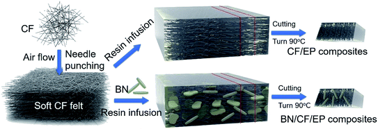
A soft mat was prepared by the airflow network technology and the needle punching method. The main steps are as follows. The CF with different lengths (2 mm, 5 mm, 10 mm, 12 cm) were put into the airtight room. As flow was introduced by the high pressure, CF moved along with the airflow. The fiber filament fell at a horizontal angle and formed soft CF felt after airflow disappears. The CF in the soft felt is arranged disorderly and randomly in an in-plane direction and possess high oriented structure. The fibers of soft felt are in physical contact without additional connection, so fibers could move freely and the stacked structures could be broken easily under an external force. For achieving the mechanical stability of the felt, fibers were needle-punched by the vertical metal pin. About 1% of fibers in the x–y plane were pushed towards the z-axis direction by the pin. It is worth noting that soft felts made of different lengths CF have the same density (0.17 g cm−3). The preparation process of soft felt is shown in Fig. 1.2.3 Preparation of BN/CF/EP composite
CF/EP composites with different contents of BN are prepared by liquid phase impregnation with the assistance of vacuum conditions. The main steps are as follows. Briefly, 2.88 g CF felts were mixed with BN alcohol solution with different solid contents for 1 hour and then the felt was transferred into the oven to dry at 80 °C for 2 hours. The corresponding mass ratios of CF and BN are 1![[thin space (1/6-em)]](https://www.rsc.org/images/entities/char_2009.gif) :
:![[thin space (1/6-em)]](https://www.rsc.org/images/entities/char_2009.gif) 2, 1
2, 1![[thin space (1/6-em)]](https://www.rsc.org/images/entities/char_2009.gif) :
:![[thin space (1/6-em)]](https://www.rsc.org/images/entities/char_2009.gif) 5, 1
5, 1![[thin space (1/6-em)]](https://www.rsc.org/images/entities/char_2009.gif) :
:![[thin space (1/6-em)]](https://www.rsc.org/images/entities/char_2009.gif) 10. Next, the oriented BN/CF felts were immersed in the prepolymer with the mass ratio of epoxy and resin of 3
10. Next, the oriented BN/CF felts were immersed in the prepolymer with the mass ratio of epoxy and resin of 3![[thin space (1/6-em)]](https://www.rsc.org/images/entities/char_2009.gif) :
:![[thin space (1/6-em)]](https://www.rsc.org/images/entities/char_2009.gif) 1 for 2 hours assisted by vacuum. After the epoxy prepolymer was filled into the holes, the felt was put into a mold and cured by a hot press under 20 MPa with 100 °C for 1 hour. The preparation process of the epoxy composite is shown in Fig. 1. The different components of the BN/CF/EP composite are displayed in Table 1.
1 for 2 hours assisted by vacuum. After the epoxy prepolymer was filled into the holes, the felt was put into a mold and cured by a hot press under 20 MPa with 100 °C for 1 hour. The preparation process of the epoxy composite is shown in Fig. 1. The different components of the BN/CF/EP composite are displayed in Table 1.
| Samples | CF (vol%) | BN (g) | BN volume fraction (vol%) |
|---|---|---|---|
| 2 mm CF/0, 8, 20, 40 vol% BN/EP | 5% | 0, 5.76, 14.4, 28.8 | 0, 8, 20, 40% |
| 5 mm CF/0, 8, 20, 40 vol% BN/EP | 5% | 0, 5.76, 14.4, 28.8 | 0, 8, 20, 40% |
| 10 mm CF/0, 8, 20, 40 vol% BN/EP | 5% | 0, 5.76, 14.4, 28.8 | 0, 8, 20, 40% |
| 12 cm CF/0, 8, 20, 40 vol% BN/EP | 5% | 0, 5.76, 14.4, 28.8 | 0, 8, 20, 40% |
2.4 Characterization
An S-2150 field-emission scanning electron microscope (SEM) from Hitachi, Japan was used to observe the morphology of CF felt and BN flakes. The samples were quenched in liquid nitrogen, and the surface to be observed was sprayed with a nanolayer of gold for clear imaging. A Rigaku D max-rA diffractometer (Japan) was used to collect X-ray diffraction patterns (XRD) of the BN material. The thermal diffusivity of the composite material was tested by a laser radiation tester (NanoFlash, LFA 457, Netzsch). The specific heat capacity of the epoxy composite material was measured using a differential scanning calorimeter (DSC) on a NETZSCH 200 F3 (Germany) instrument. Thermal conductivity (W m−1 K−1) was calculated from the product of thermal diffusivity (mm2 s−1), density (g cm−1) and specific heat (J (g−1 K−1)). At room temperature, samples of 10 mm × 10 mm × 2 mm size were placed on the heating table and the American Fluke Ti 480 instrument was used to capture the surface temperature of different samples under the same conditions. The electrical performance of the composite was measured using an Agilent E4991A impedance analyzer equipped with a 16453 A dielectric test device. A layer of gold was sprayed on the upper and lower surfaces of samples as electrodes to ensure the accuracy and reliability of data.3. Results and discussion
3.1 Preparation and morphology of CF composite
The CF filaments with different lengths were selected to construct a 3D network for CF composite due to their high aspect ratio, low density, good mechanical performance and high thermal conductivity. In order to achieve the 3D-oriented structure, airflow network technology was applied in the preparation of soft felt. Under the action of airflow, a great majority of fibers overlap each other and distribute randomly in the x–y plane. However, it is meaningful for CF felt to increase physical contact between the upper and lower fibers to enhance the stability of the CF network structure, so the needle punching method was introduced. About 1% of fibers in the x–y plane were pushed towards the z-axis direction under the action of a metal pin. The fibers oriented in the z-axis not only reinforced the 3D structure to extend but construct more vertical, thermal conductive paths in the CF skeleton. It is expected that some gaps between the adjacent fibers are still existing in the soft CF felt, though the fibers tend to be oriented in the x–y plane. These gaps mean that fibers have more possibility to be wrapped by epoxy matrix, resulting in the increase of the interface thermal resistance between the adjacent fibers during the heating transfer process. To improve this 3D structure and form the highly interconnected network, BN flakes were selected to be used in the study to improve the 3D CF structure. The soft CF felt was dipped into the BN alcohol solution to form the BN/CF skeleton, which provides more heat transfer paths for the composite with the 3D BN/CF network structure. Then, the 3D skeleton was composited with epoxy resin with the assistance of a vacuum by a liquid phase impregnation method. In order to confirm the feasibility of establishing a 3D-oriented network structure, the morphologies of the soft CF felt and composite with the CF network and CF/BN network structures were observed by SEM.From the microscopic morphology images shown in Fig. 2(a)–(c), 2 mm, 5 mm and 12 mm CF, felts are presented from the in-plane direction at the same magnification, indicating that CF felt with a longer CF skeleton has a more continuous structure. As the magnification of 12 mm CF (LCF) felt further increased, it was observed clearly that fibers are cylindrical and the surface is very smooth and regular, as shown in Fig. 2(d). The fibers with different lengths almost have the same narrow diameter of 7 μm. As expected, fibers in the soft CF felts are distributed randomly and overlap with each other in the x–y plane, which means that the 3D CF-oriented structure is successfully constructed with the introduction of the airflow network method. Moreover, it is confirmed from the microscopic morphology of soft CF felt that there are lots of gaps between the adjacent fibers. If these gaps continue to remain in the epoxy composite, a large interface thermal resistance will be generated during the heating transfer process between CF and epoxy matrix and it will reduce the thermal conductivity of the epoxy composite. In this study, hexagonal BN flakes were chosen to compound with the CF and epoxy resin to promote CF felt to form a highly interconnected structure. For verifying the composition of the second thermally conductive filler, morphology and XRD patterns of powders were obtained, as shown in Fig. 2(f). The microscopic morphology clearly presents a two-dimensional flake shape and the characteristic peaks of 26.68°, 41.67°, 43.87° and 55.14° were obviously displayed in the XRD pattern, indicating that the filler used in the study is a hexagonal BN material with much high thermal conductivity.
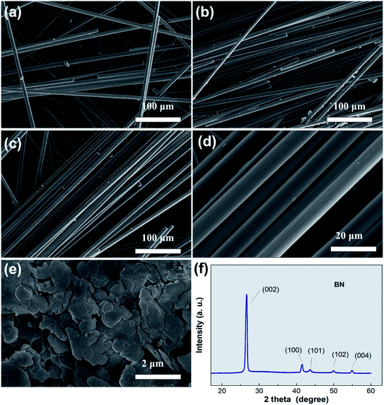 | ||
| Fig. 2 The morphology picture of (a) 2 mm CF, (b) 5 mm CF, (c and d) LCF felt (e) BN flakes. (f) The XRD pattern of BN flakes. | ||
To achieve the final composite, 3D network structures were dipped into the epoxy resin by the liquid phase impregnation method with the assistance of a vacuum. In order to estimate the combined performance between the matrix and thermally conductive fillers, the morphology of epoxy composite was observed, as shown in Fig. 3. Firstly, it could be seen that the epoxy resin was fully immersed in the holes of the felt, and fibers with different lengths are combined perfectly with the resin matrix. The phenomenon indicates that defects almost do not exist between the two-phase material and the liquid impregnation method is suitable for the composite of resin and carbon fiber skeleton. As BN flakes were added in the 3D CF skeleton, gaps between the adjacent fibers are occupied by BN flakes, as shown in Fig. 3(e) and (f). These BN flakes connected many non-contact fibers and constructed more thermal conductive pathways. Moreover, BN flakes attached to the fibers are embedded in the resin matrix, showing that CF, BN and resin matrix are tightly combined. The perfect combination of three materials reflects that the BN/CF network prepared in this study could provide much more heat transfer paths, then construct a denser 3D heat transfer structure and reduce the interface thermal resistance between fibers and resin matrix. This excellent 3D thermal conductive network structure also paves the way for the BN/CF/EP composite with high thermal conductivity.
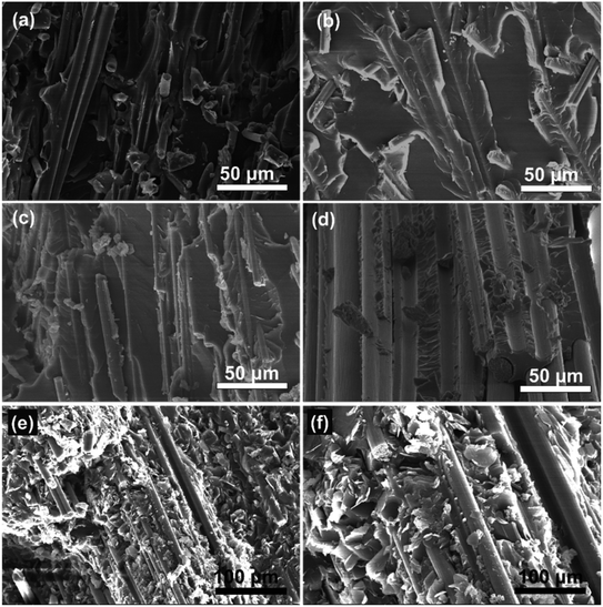 | ||
| Fig. 3 The morphology images of (a) 2 mm CF/EP composite (b) 5 mm CF/EP composite (c) 10 mm CF/EP composite (d) LCF/EP composite (e and f) LCF/20 vol% BN/EP composite. | ||
3.2 The electrical performance of BN/CF/EP composite
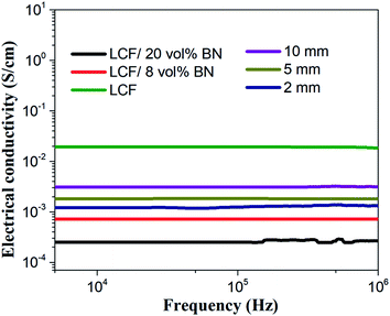
The function graph of the electrical performance changing with the frequency ranging from 5 × 10³ to 106 Hz is shown in Fig. 4. It is well known that epoxy resin is a highly electrically insulating material and the electrical conductivity of the pure epoxy resin is even lower than 10−4 S cm−1. However, it could be seen that the electrical conductivity of the composite reinforced by the 3D CF-oriented network improves significantly in the fiber axial direction. Moreover, the 3D CF skeleton constructed by longer CF has an excellent oriented effect and provides a more continuous heat conduction paths. Therefore, conductivity has a positive correlation with the fiber length and the conductivity of the CF/EP composite is improved obviously by several orders of magnitude (10−2 to 10−1 S cm−1), when the CF length reaches 12 cm.As is known, most of the materials have consistent thermal and electrical conduction laws. However, the BN material as a good insulating material possesses excellent thermal conductive performance, so it is meaningful to modify the 3D CF skeleton with the BN material. In this work, the electrical conductivity decreased sharply after the 3D CF skeleton changed into a 3D BN/CF network structure. This is because the BN material attached to the CF surface, especially CF overlapping positions, and the CF contact area was occupied by BN, leading to the blocking of electrical conduction pathways in the 3D BN/CF network. Over recent years, insulated and high thermal conductive materials have drawn increasing attention due to their broad applied fields. It is believed that this kind of composite modified by the 3D CF/BN network structure with good electrical insulation and outstanding thermal conductivity could be useful as a thermal management material in the microelectronics field.
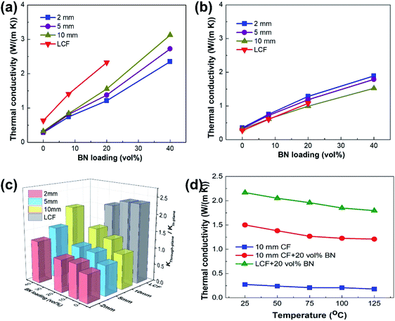
3.3 The thermal conductive performance of BN/CF/EP composite
Many microelectronic devices become high-powered and integrated, which significantly generates a lot of heat, so it is meaningful to consider the dissipation problem as a crucial issue. In order to study the heat transfer performance, the thermal conductivity (K) of the CF composite was tested by the laser flash technology from cross-plane (K⊥) and in-plane (K=) directions at 25 °C, as shown in Fig. 5(a) and (b). It is well-known that pure epoxy resin has low K, which is only about 0.2 W m−1 K−1. Herein, the 3D CF network skeleton was chosen as the thermally conductive filler to compound with the epoxy resin to construct abundant heat transfer paths in the resin matrix. It could be seen that K= of the CF/EP composite has not significantly improved as the fibers are short. As the fiber length increases, it is worth recognizing that K= of the LCF/EP composite is almost 2.2 times that of the 2 mm CF/EP composite. This phenomenon is mainly resulting from that longer fiber has a relatively higher orientation in the 3D CF skeleton and more continuous heat conduction paths are formed. Therefore, a 3D network constructed by CF with a high aspect ratio could help promote the K= of the polymer composite significantly, which provides some advice for the preparation of the thermal management material integrated into electronic devices.Some gaps existing in the 3D CF skeleton still hinder heat transfer through fibers that are oriented. It is meaningful for the 3D CF network to introduce the other thermal conductive filler to promote the continuity of the network. As expected, the introduction of the BN material results in multiple increases in K= of the composite material. K= of CF/40 vol% BN/EP increases most significantly, up to 2.4 W m−1 K−1 (2 mm), 2.7 W m−1 K−1 (5 mm) and 3.1 W m−1 K−1 (10 mm). The high K= is mainly due to the following reasons.
Firstly, K= of composite material has an obvious improvement with low BN loading. This is mainly due to the intrinsic high thermal conductivity of the BN filler. The 3D CF skeleton modified by BN flakes broadens the thermal conductive paths, which leads to a more efficient transmission of the phonons. The thermal conductive performance has an excellent improvement as BN loading increases, as shown in Fig. 5(a). Secondly, the thermal conductivity is also affected by thermal resistance at the interface between the thermally conductive filler and the resin matrix, which leads to phonon scattering and low thermal conductivity. As is reported, the continuous thermal conductive paths could form at the 60–70 vol% filler loading. However, in this study, it is obtained that K= of the composite material shows an excellent improvement at such small filler loading (5 vol% CF and 20, 40 vol% BN). This phenomenon exhibits that BN flakes connected to the adjacent fibers and continuous heat conduction paths began to be constructed gradually at low BN contents in the 3D CF network structure, which runs through the resin matrix. Apparently, such continuous heat conduction paths could reduce heat resistance and improve K= significantly. Moreover, in order to study the anisotropy of the CF composite, the value of the thermal conductive anisotropy (TCA) was calculated according to the formula K=/K⊥ at different BN loading. It is obtained that the TCA is dominated by BN loading when the 3D CF network is constructed by short fibers, as shown in Fig. 5(c). These high TCAs imply that the orientation of BN material at relatively higher loading is improved by CF space limitation and a hot press process, which reduce the in-plane thermal resistance of the composite. Under the action of BN orientation, the structure of the 3D BN/CF network is improved and values of K= of BN/CF/EP composite increase significantly. It is believed that the epoxy composite reinforced by 3D BN/CF-oriented network with good thermal conductive performance could be useful in advanced thermal management of materials in the microelectronic field.
Fig. 5(d) shows the variation of K= based on the 10 mm CF composite, 10 mm CF/20 vol% BN composite and LCF/20 vol% BN composite at different possible working temperatures. These data illustrate that K= of the three samples decreased as the temperature changed from 25 °C to 125 °C. K= of the three samples at 125 °C are reduced by 34.1% (10 mm CF), 19.5% (10 mm CF/20 vol% BN) and 17.2% (1 LCF/20 vol% BN). The thermal conductivity decreases with the increase of temperature, which is caused by the thermal expansion of the composite. With the increase of temperature, the volume of the composite expands, and the gap between resin, fiber and filler also increases, which hinders the phonon transition, and finally leads to a decrease in the thermal conductivity of the composite. The higher the temperature, the more is the thermal conductivity decreases. It could be seen that K= of the composite with 3D CF/BN network structure still maintains a high level, though the K= decline to a certain extend. Therefore, these 3D LCF/BN thermal conductive network structures could provide some advice for the development of thermal management materials in the microelectronics field.
3.4 The thermal management performance of the BN/CF/EP composite
To study the heat absorption capability of the composite with different network structures during the heat process, four samples with the same specifications of 2 mm CF composite, LCF composite, LCF/8 vol% BN composite and LCF/20 vol% BN composite, were heated on the same heating source. The surface temperatures were captured by an infrared thermal imager, as shown in Fig. 6. The thermal response performance could be evaluated by observing the changing speed of color on the sample surface. We could see that the short CF composite has a lower speed of temperature change than that of LCF composite as heating progresses, which indicates that the composite with 3D LCF network structure has better heat transfer performance. With the introduction of BN flakes, the surface color of composite with the 3D BN/CF network structure has become slightly yellow from dark purple, while the composite modified by the single CF skeleton is still purple at 2 s. After 60 s of the heating process, the surface colors of LCF/BN composite almost display the same color as the heating source but CF composites without modification by BN flakes are still at a relatively low temperature. Moreover, the LCF/20 vol% BN composite exhibits the fastest thermal response speed. This phenomenon illustrates that more denser heating transfer pathways for the composite with 3D LCF/BN network are constructed in comparison with that of the composite with the 3D CF network structure.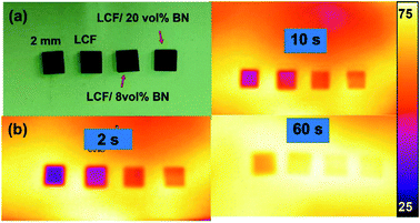 | ||
| Fig. 6 (a) An optical image and (b) the infrared thermal images of the temperature at the surface of CF composites with different CF/BN networks during the heating process. | ||
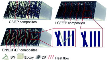
For explaining intuitively the improvement of the heat conduction effect of the composite with the introduction of BN flakes, schematic diagrams of the heat transfer mechanism of the composite reinforced by different 3D thermal conductive network structures are shown in Fig. 7. It could be seen that the separated fibers are connected by the BN thermal conductive filler. The interfacial thermal resistance and thermal scattering could be reduced by improving the thermally conductive structure with the addition of BN flakes, which effectively promotes the phonon transfer in the BN/CF network. Therefore, this 3D BN/CF network structure has great potential to be applied in advanced thermal management materials to improve the heat dissipation performance of microelectronic devices.
4. Conclusion
The epoxy composite with the 3D BN/CF oriented network structure was successfully manufactured with the assistance of the airflow network technology, needle punching and liquid phase impregnation method. The large K= of BN/CF/EP composite is mainly due to ‘BN flakes broadening the thermal conductive paths’, BN flakes increasing continues heat conduction paths' and ‘CF space constraining BN orientation effect’. It is worth noting that K= of BN/CF/EP composite with 5 vol% 10 mm CF and 40 vol% BN is improved significantly, which reaches up to 3.1 W m−1 K−1 due to the unique 3D oriented BN/CF network structure. Furthermore, the electrical conductivity has significantly decreased because of the addition of the insulated BN material. It is believed that this 3D-oriented BN/CF network structure could give some useful suggestions for the preparation of advanced thermal management material in the microelectronics field to help efficiently dissipate heat.Conflicts of interest
There are no conflicts to declare.References
- X. Yang, C. Liang, T. Ma, Y. Guo, J. Kong, J. Gu, M. Chen and J. Zhu, A review on thermally conductive polymeric composites: classification, measurement, model and equations, mechanism and fabrication methods, Adv. Compos. Hybrid Mater., 2018, 1, 207–230 CrossRef
.
- V. Goyal and A. A. Balandin, Thermal properties of the hybrid graphene-metal nano-micro-composites: applications in thermal interface materials, Appl. Phys. Lett., 2012, 100, 073113 CrossRef
.
- N. Burger, A. Laachachi, M. Ferriol, M. Lutz, V. Toniazzo and D. Ruch, Review of thermal conductivity in composites: mechanisms, parameters and theory, Prog. Polym. Sci., 2016, 61, 1–28 CrossRef CAS
.
- Y. Zhang, H. Han, N. Wang, P. Zhang, Y. Fu, M. Murugesan, M. Edwards, K. Jeppson, S. Volz and J. Liu, Improved Heat Spreading Performance of Functionalized Graphene in Microelectronic Device Application, Adv. Funct. Mater., 2015, 25, 4430–4435 CrossRef CAS
.
- J. Gu, C. Liang, X. Zhao, B. Gan, H. Qiu, Y. Guo, X. Yang, Q. Zhang and D.-Y. Wang, Highly thermally conductive flame-retardant epoxy nanocomposites with reduced ignitability and excellent electrical conductivities, Compos. Sci. Technol., 2017, 139, 83–89 CrossRef CAS
.
- D. Yang, Y. Ni, Y. Liang, B. Li, H. Ma and L. Zhang, Improved thermal conductivity and electromechanical properties of natural rubber by constructing Al2O3-PDA-Ag hybrid nanoparticles, Compos. Sci. Technol., 2019, 180, 86–93 CrossRef CAS
.
- L. Wang, H. Qiu, C. Liang, P. Song, Y. Han, Y. Han, J. Gu, J. Kong, D. Pan and Z. Guo, Electromagnetic interference shielding MWCNT-Fe3O4@Ag/epoxy nanocomposites with satisfactory thermal conductivity and high thermal stability, Carbon, 2019, 141, 506–514 CrossRef CAS
.
- Y. Lin, X. Huang, J. Chen and P. Jiang, Epoxy thermoset resins with high pristine thermal conductivity, High. Volt., 2017, 2, 139–146 CrossRef
.
- M. Owais, J. Zhao, A. Imani, G. Wang, H. Zhang and Z. Zhang, Synergetic effect of hybrid fillers of boron nitride, graphene nanoplatelets, and short carbon fibers for enhanced thermal conductivity and electrical resistivity of epoxy nanocomposites, Compos. Appl. Sci. Manuf., 2019, 117, 11–22 CrossRef CAS
.
- H. M. Ragab and A. Rajeh, Structural, thermal, optical and conductive properties of PAM/PVA polymer composite doped with Ag nanoparticles for electrochemical application, J. Mater. Sci. Mater. Electron., 2020, 31, 16780–16792 CrossRef CAS
.
- C. Ji, Y. Wang, Z. Q. Ye, L. Y. Tan, D. S. Mao, W. G. Zhao, X. L. Zeng, C. Z. Yan, R. Sun, D. J. Kang, J. B. Xu and C. P. Wong, Ice-Templated MXene/Ag-Epoxy Nanocomposites as High-Performance Thermal Management Materials, ACS Appl. Mater. Interfaces, 2020, 12, 24298–24307 CrossRef CAS PubMed
.
- Y. Kim, S. Lee and J. Kim, Enhanced Thermal Conductivity of Epoxy Composites Filled with Cu Foam and Functionalized with MWCNT 3D Network, Polymer, 2021, 45, 56–61 CAS
.
- F. Xu, Y. Cui, D. Bao, D. Lin, S. Yuan, X. Wang, H. Wang and Y. Sun, A 3D interconnected Cu network supported by carbon felt skeleton for highly thermally conductive epoxy composites, Chem. Eng. J., 2020, 388, 124287 CrossRef CAS
.
- H. Wang, L. Li, Y. Chen, M. Li, H. Fu, H. Xiao, X. Wu, C.-T. Lin, N. Jiang and J. Yu, Efficient Thermal Transport Highway Construction Within
Epoxy Matrix via Hybrid Carbon Fibers and Alumina Particles, ACS Omega, 2020, 5, 1170–1177 CrossRef CAS PubMed
.
- M. H. A. Kudus, M. R. Zakaria, M. F. Omar, M. B. H. Othman, H. M. Akil, M. Nabialek, B. Jez and M. M. A. B. Abdullah, Nonisothermal Kinetic Degradation of Hybrid CNT/Alumina Epoxy Nanocomposites, Metals, 2021, 11, 657 CrossRef
.
- J. Chen, X. Huang, B. Sun, Y. Wang, Y. Zhu and P. Jiang, Vertically Aligned and Interconnected Boron Nitride Nanosheets for Advanced Flexible Nanocomposite Thermal Interface Materials, ACS Appl. Mater. Interfaces, 2017, 9, 30909–30917 CrossRef CAS PubMed
.
- X. Zeng, J. Sun, Y. Yao, R. Sun, J.-B. Xu and C.-P. Wong, A Combination of Boron Nitride Nanotubes and Cellulose Nanofibers for the Preparation of a Nanocomposite with High Thermal Conductivity, ACS Nano, 2017, 11, 5167–5178 CrossRef CAS PubMed
.
- Y. Han, X. Shi, S. Wang, K. Ruan, C. Lu, Y. Guo and J. Gu, Nest-like hetero-structured BNNS@SiCnws fillers and significant improvement on thermal conductivities of epoxy composites, Compos. B Eng., 2021, 210, 108666 CrossRef CAS
.
- C.-R. Yang, C.-D. Chen, C. Cheng, W.-H. Shi, P.-H. Chen and T.-P. Teng, Thermal conductivity enhancement of AlN/PDMS composites using atmospheric plasma modification techniques, Int. J. Therm. Sci., 2020, 155, 106431 CrossRef CAS
.
- T. Yao, K. Chen, T. Shao, C. Zhang, C. Zhang and Y. Yang, Nano-BN encapsulated micro-AlN as fillers for epoxy composites with high thermal conductivity and sufficient dielectric breakdown strength, IEEE Trans. Dielectr. Electr. Insul., 2020, 27, 528–534 CAS
.
- D. Liang, P. Ren, F. Ren, Y. Jin, J. Wang, C. Feng and Q. Duan, Synergetic enhancement of thermal conductivity by constructing BN and AlN hybrid network in epoxy matrix, J. Polym. Res., 2020, 27, 212 CrossRef CAS
.
- A. Shimamura, Y. Hotta, H. Hyuga, M. Hotta and K. Hirao, Improving the thermal conductivity of epoxy composites using a combustion-synthesized aggregated beta-Si3N4 filler with randomly oriented grains (vol. 10, 14926, 2020), Sci. Rep., 2020, 10, 22399 CrossRef CAS PubMed
.
- X. Liu, D. Zhang, Y. Liu, J. Liu, X. Yang, Y. Gao and A. Ma, Promotion of the mechanical properties and thermal conductivity of epoxy by low Si3N4 whisker content and its mechanisms, J. Appl. Polym. Sci., 2020, 137, 48721 CrossRef CAS
.
- A. Shimamura, Y. Hotta, H. Hyuga, N. Kondo and K. Hirao, Effect of amounts and types of silicon nitride on thermal conductivity of Si3N4/epoxy resin composite, J. Ceram. Soc. Jpn., 2015, 123, 908–912 CrossRef CAS
.
- A. Ali, A. Andriyana, S. B. A. Hassan and B. C. Ang, Fabrication and Thermo-Electro and Mechanical Properties Evaluation of Helical Multiwall Carbon Nanotube-Carbon Fiber/Epoxy Composite Laminates, Polymers, 2021, 13, 1437 CrossRef CAS PubMed
.
- F. Yildirim, N. Ataberk and M. Ekrem, Mechanical and thermal properties of a nanocomposite material which epoxy based and reinforced with polyvinyl alcohol nano fibers contained multiwalled carbon nanotube, J. Compos. Mater., 2021, 55, 1339–1347 CrossRef CAS
.
- C. Cheng, M. Zhang, S. Wang, Y. Li, H. Feng, D. Bu, Z. Xu, Y. Liu, L. Jin, L. Xiao and Y. Ao, Improving interfacial properties and thermal conductivity of carbon fiber/epoxy composites via the solvent-free GO@Fe3O4 nanofluid modified water-based sizing agent, Compos. Sci. Technol., 2021, 209, 108788 CrossRef
.
- T. Wang, Q. Song, S. Zhang, K. Li, C. Xiao, H. Lin, Q. Shen and H. Li, Simultaneous enhancement of mechanical and electrical/thermal properties of carbon fiber/polymer composites via SiC nanowires/graphene hybrid nanofillers, Compos. Appl. Sci. Manuf., 2021, 145, 106404 CrossRef
.
- X. Wu, Y. Gao, T. Jiang, L. Zheng, Y. Wang, B. Tang, K. Sun, Y. Zhao, W. Li, K. Yang and J. Yu, 3D Thermal Network Supported by CF Felt for Improving the Thermal Performance of CF/C/Epoxy Composites, Polymers, 2021, 13, 980 CrossRef CAS PubMed
.
- H. Li, L. Jin, J. Dong, L. Liu, M. Li, Y. Liu, L. Xiao and Y. Ao, Tribological performance and thermal conductivity of graphene-Fe3O4/poly(phenol-formaldehyde resin) hybrid reinforced carbon fiber composites, RSC Adv., 2016, 6, 60200–60205 RSC
.
- Y. Guo, X. Yang, K. Ruan, J. Kong, M. Dong, J. Zhang, J. Gu and Z. Guo, Reduced Graphene Oxide Heterostructured Silver Nanoparticles Significantly Enhanced Thermal Conductivities in Hot-Pressed Electrospun Polyimide Nanocomposites, ACS Appl. Mater. Interfaces, 2019, 11, 25465–25473 CrossRef CAS PubMed
.
- Y. Guo, K. Ruan, X. Yang, T. Ma, J. Kong, N. Wu, J. Zhang, J. Gu and Z. Guo, Constructing fully carbon-based fillers with a hierarchical structure to fabricate highly thermally conductive polyimide nanocomposites, J. Mater. Chem. C, 2019, 7, 7035–7044 RSC
.
- J. Chen, X. Huang, B. Sun and P. Jiang, Highly Thermally Conductive Yet Electrically Insulating Polymer/Boron Nitride Nanosheets Nanocomposite Films for Improved Thermal Management Capability, ACS Nano, 2019, 13, 337–345 CrossRef CAS PubMed
.
- M. Mu, C. Wan and T. McNally, Thermal conductivity of 2D nano-structured graphitic materials and their composites with epoxy resins, 2d Mater., 2017, 4, 042001 CrossRef
.
- N. Song, H. Pan, X. Hou, S. Cui, L. Shi and P. Ding, Enhancement of thermal conductivity in polyamide-6/graphene composites via a "bridge effect" of silicon carbide whiskers, RSC Adv., 2017, 7, 46306–46312 RSC
.
- X. F. Wu, B. Tang, J. Chen, L. M. Shan, Y. Gao, K. Yang, Y. Wang, K. Sun, R. H. Fan and J. H. Yu, Epoxy composites with high cross-plane thermal conductivity by constructing all-carbon multidimensional carbon fiber/graphite networks, Compos. Sci. Technol., 2021, 203, 108610 CrossRef CAS
.
- J. M. Wei, M. Z. Liao, A. J. Ma, Y. P. Chen, Z. H. Duan, X. Hou, M. H. Li, N. Jiang and J. H. Yu, Enhanced thermal conductivity of polydimethylsiloxane composites with carbon fiber, Compos. Commun., 2020, 17, 141–146 CrossRef
.
- T. Xu, S. Zhou, S. Cui, N. Song, L. Shi and P. Ding, Three-dimensional carbon fiber-graphene network for improved thermal conductive properties of polyamide-imide composites, Compos. B Eng., 2019, 178, 107495 CrossRef CAS
.
- Y. Liu, J. Luo, C. Helleu, M. Behr, H. Ba, T. Romero, A. Hebraud, G. Schlatter, O. Ersen, D. S. Su and C. Pham-Huu, Hierarchical porous carbon fibers/carbon nanofibers monolith from electrospinning/CVD processes as a high effective surface area support platform, J. Mater. Chem. A, 2017, 5, 2151–2162 RSC
.
- L. Li, W. Liu, F. Yang, W. Jiao, L. Hao and R. Wang, Interfacial reinforcement of hybrid composite by electrophoretic deposition for vertically aligned carbon nanotubes on carbon fiber, Compos. Sci. Technol., 2020, 187, 107946 CrossRef CAS
.
- X.-w. Zhao, C.-g. Zang, Q.-k. Ma, Y.-q. Wen and Q.-j. Jiao, Thermal and electrical properties of composites based on (3-mercaptopropyl) trimethoxysilane- and Cu-coated carbon fiber and silicone rubber, J. Mater. Sci., 2016, 51, 4088–4095 CrossRef CAS
.
- Y. Sun, S. Wang, M. Li, Y. Gu and Z. Zhang, Improvement of out-of-plane thermal conductivity of composite laminate by electrostatic flocking, Mater. Des., 2018, 144, 263–270 CrossRef CAS
.
- Z. Yu, S. Wei and J. Guo, Fabrication of aligned carbon-fiber/polymer TIMs using electrostatic flocking method, J. Mater. Sci. Mater. Electron., 2019, 30, 10233–10243 CrossRef CAS
.
- X. Li, J. Wang, K. Wang, J. Yao, H. Bian, K. Song, S. Komarneni and Z. Cai, Three-dimensional stretchable fabric-based electrode for supercapacitors prepared by electrostatic flocking, Chem. Eng. J., 2020, 390, 124442 CrossRef CAS
.
- L. Guo, Z. Zhang, M. Li, R. Kang, Y. Chen, G. Song, S.-T. Han, C.-T. Lin, N. Jiang and J. Yu, Extremely high thermal conductivity of carbon fiber/epoxy with synergistic effect of MXenes by freeze-drying, Compos. Commun., 2020, 19, 134–141 CrossRef
.
- J. Ma, T. Shang, L. Ren, Y. Yao, T. Zhang, J. Xie, B. Zhang, X. Zeng, R. Sun, J.-B. Xu and C.-P. Wong, Through-plane assembly of carbon fibers into 3D skeleton achieving enhanced thermal conductivity of a thermal interface material, Chem. Eng. J., 2020, 380, 122550 CrossRef CAS
.
- D. Suh, C. M. Moon, D. Kim and S. Baik, Ultrahigh Thermal Conductivity of Interface Materials by Silver-Functionalized Carbon Nanotube Phonon Conduits, Adv. Mater., 2016, 28, 7220–7227 CrossRef CAS PubMed
.
- S. Guo, R. Zheng, J. Jiang, J. Yu, K. Dai and C. Yan, Enhanced thermal conductivity and retained electrical insulation of heat spreader by incorporating alumina-deposited graphene filler in nano-fibrillated cellulose, Compos. B Eng., 2019, 178, 107489 CrossRef CAS
.
- M. Loeblein, S. H. Tsang, M. Pawlik, E. J. R. Phua, H. Yong, X. W. Zhang, C. L. Gan and E. H. T. Teo, High-Density 3D-Boron Nitride and 3D-Graphene for High-Performance Nano-Thermal Interface Material, ACS Nano, 2017, 11, 2033–2044 CrossRef CAS PubMed
.
Footnote |
| † These authors contributed equally. |
| This journal is © The Royal Society of Chemistry 2021 |

