 Open Access Article
Role of tribochemistry reactions of B4C on tribofilm growth at a PEEK–steel interface in simulated body fluids
Gen Liuab,
Guitao Li*ac,
Fuyan Zhaoac,
Nikolai K. Myshkin d and
Ga Zhang
 *ac
*ac
aState Key Laboratory of Solid Lubrication, Lanzhou Institute of Chemical Physics, Chinese Academy of Sciences, Lanzhou 730000, China. E-mail: gzhang@licp.cas.cn; gtli@licp.cas.cn; Fax: +86 931 4968180; Tel: +86-931-4968041
bCenter of Materials Science and Optoelectronics Engineering, University of Chinese Academy of Sciences, Beijing 100049, China
cQingdao Center of Resource Chemistry & New Materials, Qingdao 266071, China
dV.A. Belyi Metal–Polymer Research Institute, National Academy of Sciences of Belarus, Gomel 246050, Belarus
First published on 5th October 2021
Abstract
Corrosion and wear products of metallic implants can lead to severe adverse tissue reactions. However, there is an absence of effective means to reduce the tribocorrosion of metal. The main purpose of this study is to reveal a mechanism of engineering a barrier layer on metal surfaces via adding functional particles into the polymer counterpart. B4C and BN particles were compounded into a polyetheretherketone (PEEK) matrix and their tribological performance of PEEK-based composites sliding against stainless steel was compared in simulated body fluid. Results demonstrate that the addition of B4C reduces significantly friction and wear. In particular, the addition of only 1 vol% B4C reduces wear of PEEK by up to 94.8%, and tribocorrosion of steel is also obviously mitigated. It is discovered that hydrolysis of B4C particles triggered by friction and deposition of Ca2+ and phosphate ions dominate formation of the barrier layer at the friction interface. The barrier layer endows the PEEK–metal sliding pair simultaneously enhanced anti-wear and anti-corrosion performance.
1. Introduction
In the past few decades, the incidence rate of osteoarthritis has been increasing year by year with the growing incidence of obesity and aging of the population. Artificial joint replacement has been commonly regarded as the most effective clinical method in the treatment of advanced joint diseases. To pursue a higher quality of life, total joint arthroplasty procedures have been conducted to restore the function of joints and resume normal daily activities for people. In 2018, the number of patients receiving an artificial joint replacement reached 698![[thin space (1/6-em)]](https://www.rsc.org/images/entities/char_2009.gif) 583 in China,1 and by 2030, TKA demand in the United States is predicted to increase by 673% compared with 2015.2 The number of surgeries of joint replacement will maintain rapid growth in the foreseeable future. Therefore, it is of great significance to develop joint prosthesis materials with higher performance and reliability since the failure of implants often leads to revision surgery which carries a higher risk of complications.
583 in China,1 and by 2030, TKA demand in the United States is predicted to increase by 673% compared with 2015.2 The number of surgeries of joint replacement will maintain rapid growth in the foreseeable future. Therefore, it is of great significance to develop joint prosthesis materials with higher performance and reliability since the failure of implants often leads to revision surgery which carries a higher risk of complications.
Most implants are usually made of ceramics, polymers, or metals. Ceramic components possess good wear resistance and chemical inertness, nevertheless, the fracture and the squeaking of ceramic joints have gained much attention.3,4 Moreover, the high elastic modulus of ceramics can also be an issue, a consequent stress shielding effect may weaken the underlying bone and cause fracture.5–9 Polyethylene has been the most widely used polymeric material since 1960 when Charnley first utilized it as an acetabular liner.10 However, mismatching between UHMWPE components and its counterpart owing to the creep can cause a lot of wear.11 Besides, stimulated adverse tissue reactions due to UHMWPE wear debris are proved to be an important factor leading to osteolysis.12 Polyetheretherketone (PEEK) based materials have been regarded as promising bone substitute materials, for example, PEEK based spinal implants have been widely applied in the clinical field for their excellent mechanical properties, chemical stability, and biocompatibility.13,14 Besides, the elastic modulus comparable to cortical bone and design flexibility taking advantage of 3D printing also may bring PEEK a broad application prospect.15–17
Inert metal is widely employed in joint implants as femoral heads and conjunction parts. A passive layer formed on the inert metal surface serves as a barrier to separate metal under the passive layer from electrolytes. Sliding or fretting between inert metal and hard counterparts immersed in electrolyte breaks up the dynamic electrochemical equilibrium at the metal/electrolyte interface.18 Damage to the passive layer on the inert metal surface results in a severely synergetic effect of wear and corrosion, i.e. tribocorrosion,19,20 which releases a large number of metal ions and debris. Metal ions and debris lead to an inflammatory reaction, tissue necrosis, systemic toxicity, and finally failure of joint replacement.21–23
Tribofilm growth has been identified in previous works at the interface of artificial joints tested in vivo and in vitro. Actually, the concept of tribofilm has become the development of the earlier models related to the friction transfer layers resulting in formation of third body between two rubbing solids. Brief historical review of such phenomena in application to boundary lubrication is presented by Myshkin.24 Tribofilms generated owing to complex tribochemical reactions comprise a variety of compositions ranging from oxide films to organic, carbonaceous, or graphitic layers.3,25–29 Hesketh et al.29 investigated nanostructures of the tribofilm on a cobalt–chromium (CoCr) alloys surface tested in a hip simulator and proposed that the tribochemical layer could act as a solid lubricant layer to reduce friction. Liao et al.27 have suggested that promoting the formation of tribofilm could be a promising strategy to improve corrosion performance. Mathew et al.30 studied the influence of the tribofilm on the electrochemical properties of implants and found that the tribofilm covering the metal surface alleviate significantly corrosion.
Our recent work,31 demonstrates that adding low-loading tribo-hydrolyzable silicon carbide nanoparticles into PEEK significantly improves wear resistance of PEEK when being slid against stainless steel immersed in simulated body fluid (SBF). More interestingly, corrosion and wear of the steel are alleviated due to the formation of a tribofilm. The work provides a hint for optimizing tribocorrosion performance of polymer–metal joints by controlling tribofilm growth at the friction interface. Tribofilm growth is governed by complex tribo-physical and chemical actions triggered by frictional heat and stress.32–34 Although pioneering works have been conducted for gaining insight into tribofilm growth in engineering surfaces, mechanisms governing tribofilm growth at a joint interface in body fluid is not understood yet.
Hexagonal boron nitride (h-BN) and boron carbide (B4C) are both considered to have good biocompatibility.35,36 H-BN has a layer structure and has been widely used as a solid lubricant.37,38 B4C has a cubic structure and exhibits high wear resistance.39 More interestingly, when h-BN and B4C are exposed to friction interface, hydrolysis reactions of the boron compounds can take place, and thus play a role in following friction procedure.40 In this study, h-BN and B4C particles are compounded into PEEK matrices, respectively. Tribological performance of neat PEEK, PEEK/B4C, and PEEK/BN when sliding against stainless steel in SBF were comparatively studied. In order to identify possible effect of electrolyte's ingredients on tribofilm growth, normal saline, Hank's solution and modified Hank's solution were utilized as lubricating mediums. Nanostructures of tribofilms growing on the steel surface were thoroughly characterized. To deeply understand the role of tribofilm on tribocorrosion behavior of the steel counterpart, tribo-electrochemical tests were conducted. Main aim of the present work is to deepen understanding of formation and function mechanisms of tribofilm at the interface of polymer–metal pair in electrolytes. It is the objective of this work to explore possible strategies for engineering a protective barrier layer at the friction interface of artificial joints. Note that further simulating tests are required in future work for validating more influential factors. It is expected the output of this work will open an avenue for developing polymer joint implanting materials of enhanced performance.
2. Experimental
2.1 Materials preparation
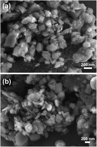
PEEK powders were purchased from Victrex (PF 450G, UK) with an average diameter of 45 μm. B4C and h-BN were obtained from Beijing Deke Daojin Science and Technology Co., Ltd. The average diameters of B4C (135 nm) and h-BN (167 nm) particles were determined by measuring diameters of over 100 particles, respectively. The morphology of particles was observed using scanning electron microscopy (SEM) as shown in Fig. 1. All raw materials were washed by petroleum ether and ethanol, then dried in an oven at 80 °C. 1 vol% B4C and 1 vol% BN were compounded into PEEK, respectively, using a lab-scale internal mixer (Rheomix PolylabQC, Haake, Thermo Fisher Scientific, USA) at 380 °C with a rotor speed of 80 rpm, and the mixtures were compression molded into plates with a dimension of 80 × 80 × 5 mm3. Finally, they were shaped into plates with a dimension of 50 × 10 × 4 mm3 for a tribological test. The PEEK composites were denominated as PEEK/B4C and PEEK/BN. Neat PEEK was used as a control.2.2 Tribological tests
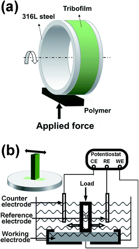
Plate-on-ring (MRH-3, Jinan Yihua Tribology Testing Technology Co., Ltd., China) tests were conducted for evaluating the tribological performance of the PEEK-based materials while sliding against a 316L (AISI) stainless steel ring in SBF. The outer diameter of the steel ring was 60 mm. The mean roughness Ra of the steel ring and the polymer plates were 0.04 μm and 0.10 μm, respectively. The schematic of the contact configuration of the plate-on-ring test is illustrated in Fig. 2a All tests were performed at 25 °C (±2 °C) and with a humidity of about 55% (±5%). With plate-on-ring tests, it is convenient to control the lubrication regime by varying the applied load and the sliding speed. The sliding speed was decreased in steps from 0.8 m s−1 to 0.02 m s−1 to evaluate the tribological behaviors in different lubrication regimes. In follow-up tests, the load was still maintained at 400 N and the sliding speed was fixed at 0.05 m s−1 since artificial knee joints mainly operate in mixed and boundary regimes.41 As calculated according to the Hamrock–Dowson formula,42 the Lamda ratio was 0.07 and, thus the sliding pairs concerned lied in the boundary lubrication regime.As demonstrated in our previous work,31 the tribofilm growing at the interface of polymer-on-metal friction pair immersed in Hank's solution contains significant Ca and P elements. To identify crucial ingredients in the electrolytes determining tribofilm formation, three kinds of electrolytes, i.e. normal saline solution (referenced as 0.9% NaCl), saline solution doped with Ca2+ and phosphate ions (referenced as NaCl/Ca/P), and Hank's solution, were compared. Detailed compositions of the three electrolytes are listed in Table 1. Wear volumes of the PEEK plates were calculated according to wear scar widths, as described in detail in our previous work.31 Each test was repeated three times, after the test the steel rings and polymer pins were carefully washed with deionized water and dried up for further characterizations.
| Ion | Ion concentrations (mM) | ||
|---|---|---|---|
| 0.9% NaCl | NaCl/Ca/P | Hank's | |
| Na+ | 153.85 | 151.33 | 138 |
| Cl− | 153.85 | 152.29 | 144.8 |
| Ca2+ | 1.26 | 1.26 | |
| Phosphate ions | 0.78 | 0.78 | |
| K+ | 6.14 | ||
| HCO3− | 4.2 | ||
| Mg2+ | 0.81 | ||
| SO42− | 0.81 | ||
2.3 Tribo-electrochemical tests
A tribo-electrochemical testing system was employed to investigate the electrochemical behaviors of the metal when sliding against the PEEK composites. A UMT tribometer (TriboLab, Bruker, USA) was used for realizing reciprocating oscillation between a polymer pin and a 316L stainless steel. Electrochemical signals were recorded using an electrochemical workstation (CHI660e, Shanghai Chenhua Instrument Co., Ltd., China). The potentials were recorded against Ag/AgCl (SSE) reference electrode in Hank's solution at 37 °C, and a platinum wire (about 8 cm) was used as the counter electrode. Metallic sheets of 316L stainless steel were shaped with a dimension of 25 × 25 × 2.5 mm3 and finished with SiC abrasive paper to gain a surface roughness (Ra) of 0.04 nm. Polymer pins were given a length of 12 mm and square cross-section with the side length of 4 mm and the Ra of 0.1 μm. All tests were performed with the amplitude of 4 mm and a frequency of 3 Hz. The schematic of the tribo-electrochemical tests was illustrated in Fig. 2b.2.4 Surface characterization
Roughness of the steel ring and the polymer plates were checked using 3D Optical Surface Profiler (MicroXAM-800, KLA-Tenor, USA). After friction, surfaces of the steel rings were inspected using an optical microscope (Olympus BX41, Japan) and a Field Emission Scanning Electron Microscope (FE-SEM, Merlin Compact, Carl Zeiss, Germany). The worn surface of the PEEK samples was inspected with the 3D Optical Surface Profiler as well. Element distribution on worn surfaces of the metallic rings was carried out using an Energy Dispersive X-ray Spectroscopy (EDS) instrumented onto the FE-SEM. Chemical states of the metallic worn surface were analyzed by using an X-ray Photoelectron Spectrometer (XPS, ESCALAB 250Xi, Thermo Fisher Scientific, USA), the data were obtained using a monochromatic Al Kα radiation. A cross-sectional lamella of the steel surface layer was machined using Focused Ion Beam (FIB) in a Dual Beam SEM/FIB instrument (FEI, Netherlands) and a High-Resolution Transmission Electron Microscope (HR-TEM, Tecnai G2 TF30 S-TWIN, FEI, Netherlands) was used characterizing nanostructures of the tribofilm.3. Results and discussions
3.1 Friction coefficient (COF) and wear volume
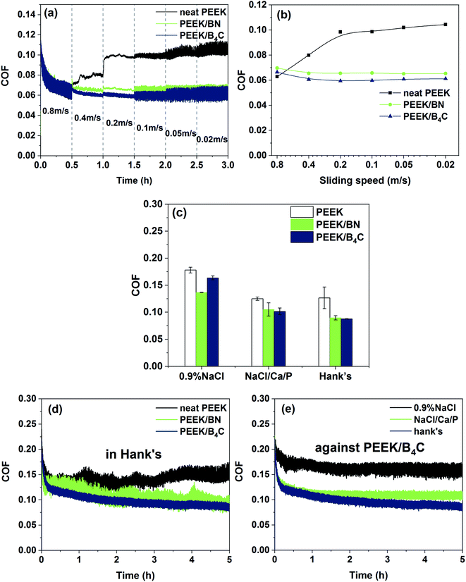
Fig. 3a shows COF tendencies of the three PEEK-based materials in Hank's while stepwise decreasing the sliding speed from 0.8 m s−1 to 0.02 m s−1. Fig. 3b illustrates Stribeck curves of the sliding pairs based on average COF obtained from each step. As seen from Fig. 3a and b, COF of PEEK increases significantly with decreasing the speed from 0.8 m s−1 to 0.2 m s−1 due to reduced hydrodynamic pressure of the liquid film. Nevertheless, further decrement of the sliding speed from 0.2 m s−1 to 0.02 m s−1 does not lead to obvious COF variation, giving a hint that the system shifts from mixed to boundary lubrication regime. With respect to the sliding of PEEK/BN and PEEK/B4C, the COF does not increase significantly while decreasing the speed from 0.8 m s−1 to 0.02 m s−1. In the speed range from 0.6 to 0.02 m s−1, PEEK/BN and PEEK/B4C exhibits lower COFs than pure PEEK. As described below, BN and B4C particles exposed to sliding interface helps to form a lubricating tribofilm. It is thus surmised that when sliding takes place under harsh lubricating conditions, the tribofilm can compensate for lubricating insufficiency of the liquid film.Fig. 3c compares average COFs of PEEK, PEEK/BN, and PEEK/B4C when sliding with 316L stainless steel in 0.9% NaCl, NaCl/Ca/P, and Hank's solution, respectively. When sliding takes place in the two solutions containing Ca2+ and phosphate ions, i.e. NaCl/Ca/P and Hank's, the COFs of all the PEEK-based materials are always lower than those obtained in 0.9% NaCl. Moreover, the PEEK-based materials exhibit similar COFs when sliding takes place in NaCl/Ca/P and Hank's. Therefore, it is demonstrated that the presence of Ca2+ and phosphate ions in the electrolytes play an important role in friction reduction. When sliding with 316L stainless steel in NaCl/Ca/P and Hank's, PEEK/B4C and PEEK/BN exhibits lower COFs than PEEK. Fig. 3d illustrates COF evolutions of PEEK, PEEK/BN, and PEEK/B4C in Hank's. In contrast to sliding of PEEK and PEEK/BN, the COF of PEEK/B4C shows significantly suppressed fluctuation. This can give a hint that the friction interface between PEEK/B4C and metal is more stable probably due to the formation of a stable tribofilm. As seen from Fig. 3e, when PEEK/B4C slides with 316L stainless steel in NaCl/Ca/P and Hank's, fluctuation of COFs is obviously suppressed in comparison to that obtained in 0.9% NaCl. As described below, B4C particles and Ca2+, phosphate ions at a friction interface helps to form the high performance tribofilm.
Fig. 4 illustrates wear volumes of PEEK, PEEK/BN, and PEEK/B4C when sliding in 0.9% NaCl, NaCl/Ca/P, and Hank's. The addition of B4C or BN particles decreases significantly the wear of PEEK when sliding in all three electrolytes. Among the three PEEK-based materials, PEEK/B4C shows the lowest wear. For example, when sliding occurs in Hank's, the addition of BN reduces the wear of PEEK by 73.3%. What's more interesting, adding only 1 vol% B4C reduces the wear of PEEK by 94.8%. That is, the addition of B4C improves the wear resistance of PEEK by nearly 20 times. Similar to the tendency of COF, the three PEEK-based materials exhibit lower wear when sliding in the two electrolytes containing Ca2+ and phosphate ions than that in 0.9% NaCl, indicating pronounced wear reduction role of the Ca2+ and phosphate ions. With respect to sliding of PEEK/B4C, the wear loss in Hank's is reduced by 73.8% when compared to that in 0.9% NaCl. Whereas, the PEEK-based materials have similar wear loss when sliding in NaCl/Ca/P and Hank's. It is hence inferred Ca2+ and phosphate ions in SBF plays a crucial lubrication role. It seems that the lubrication effect of K+ HCO3− Mg2+ SO42− ions is not pronounced.
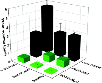 | ||
| Fig. 4 Wear volumes of PEEK, PEEK/BN and PEEK/B4C when sliding against 316L stainless steel in 0.9% NaCl, NaCl/Ca/P and Hank's. | ||
3.2 Surface analyses
Fig. 5 and 6 illustrate optical micrographs and 3D topographies of the metal surfaces rubbed respectively with neat PEEK, PEEK/BN, and PEEK/B4C in 0.9% NaCl, NaCl/Ca/P, and Hank's. Deep grooves are noticed on the metal surface rubbed with PEEK in the three electrolytes (cf. Fig. 5a–c and 6a–c). Generation of the deep abrasion grooves on metal surface is ascribed to continuous damage of the passive layer, for which mechanical abrasion and corrosion accelerate mutually.43 However, when sliding takes place in the two electrolytes containing Ca2+ and phosphate ions, abrasion marks on the metal surface rubbed with neat PEEK is mitigated in comparison to that in 0.9% NaCl. Being consistent with the above friction and wear results, the lubricating effect of Ca2+ and phosphate ions in the electrolytes is thus corroborated.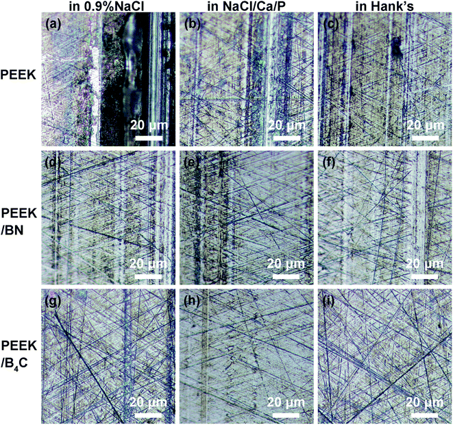 | ||
| Fig. 5 Optical micrographs of 316L stainless steel surfaces after rubbing with (a–c) neat PEEK, (d) PEEK/BN, (g–i) PEEK/B4C in 0.9% NaCl (a, d and g), NaCl/Ca/P (b, e and h), and Hank's (c, f and i). | ||
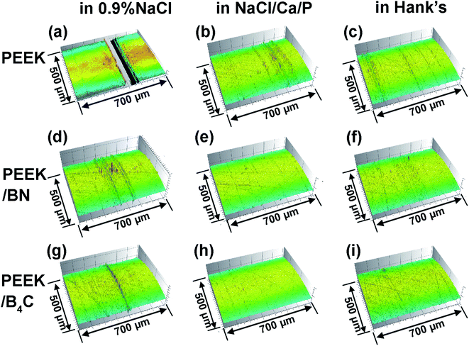 | ||
| Fig. 6 3D surface topographies of the metal surfaces after rubbing with (a–c) neat PEEK, (d–f) PEEK/BN, (g–i) PEEK/B4C in 0.9% NaCl (a, d and g), NaCl/Ca/P (b, e and h), and Hank's (c, f and i). | ||
The addition of BN into PEEK mitigates abrasion marks on the metal surface, as noticed from Fig. 5d–f and 6d–f. As shown below, the transfer of BN from the PEEK composite onto the metal surface occurs, which is assumed to be the main reason for the lower friction and wear. As seen from Fig. 5h, i, 6h and i, only very mild abrasion marks are noticed from the metal surfaces rubbed with PEEK/B4C in electrolytes containing Ca2+ and phosphate ions. As consistent with the COF and wear results (Fig. 3 and 4), the excellent lubricating effect of B4C particles is verified. Additionally, a synergistic role between B4C particles and Ca2+, phosphate ions is identified.
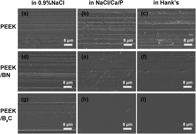
Fig. 7 illustrates SEM micrographs of worn surfaces of neat PEEK, PEEK/BN, and PEEK/B4C rubbed with 316L stainless steel in 0.9% NaCl, NaCl/Ca/P, and Hank's solution, respectively. Obvious abrasion grooves are noticed from Fig. 7a–c on neat PEEK surfaces. It is surmised that the abrasion grooves were caused by the protruding asperities on the metal surface and wear particles generated due to the tribocorrosion process. Moreover, when sliding takes place in 0.9% NaCl, obvious abrasion grooves are always observed on the surfaces of PEEK, PEEK/BN, and PEEK/B4C (cf. Fig. 7a, d, and g). Among them, there are the least grooves on the surface of PEEK/B4C. However, when sliding takes place in the electrolytes containing Ca2+ and phosphate ions, mechanical abrasion of the PEEK-based materials is much mitigated (Fig. 7e, f, h, and i). In particular, the worn surfaces of PEEK/B4C after sliding in NaCl/Ca/P and Hank's are rather smooth and no severe abrasion marks are noticed from Fig. 6h and i.
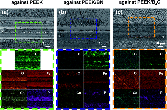
From Fig. 8, significant Ca, and P elements are identified on the metal surfaces rubbed with neat PEEK, PEEK/BN, and PEEK/B4C. What's more, distribution of P, Ca and O elements coincide well with each other on the metal surfaces. Hence, it is inferred that precipitation of Ca2+ and phosphate ions occurs and as a result plays a protective role on the metal surface against mechanical abrasion and corrosion. Besides, C element is detected on the metal surfaces rubbed with the three PEEK-based materials, indicating transfer of polymer matrix. Nevertheless, in spite of precipitation of Ca2+ and phosphate ions, abrasion marks are noticed on the metal surface after being slid against neat PEEK. In contrast, abrasion marks on the metal surfaces slid against PEEK/BN and PEEK/B4C are milder than those slid against neat PEEK (cf. Fig. 8a, b and c). Moreover, the B element is identified from both surfaces rubbed with PEEK/BN and PEEK/B4C. Closer inspections on the EDS maps show that Ca and P elements are not present in the abrasion grooves on the metal surface rubbed with PEEK/BN. Whereas, Ca and P elements distribute uniformly on the metal surface rubbed with PEEK/B4C. This can give a hint that the tribofilm on the metal surface rubbed with PEEK/B4C is more resilient than that formed on the metal surface rubbed with PEEK/BN.
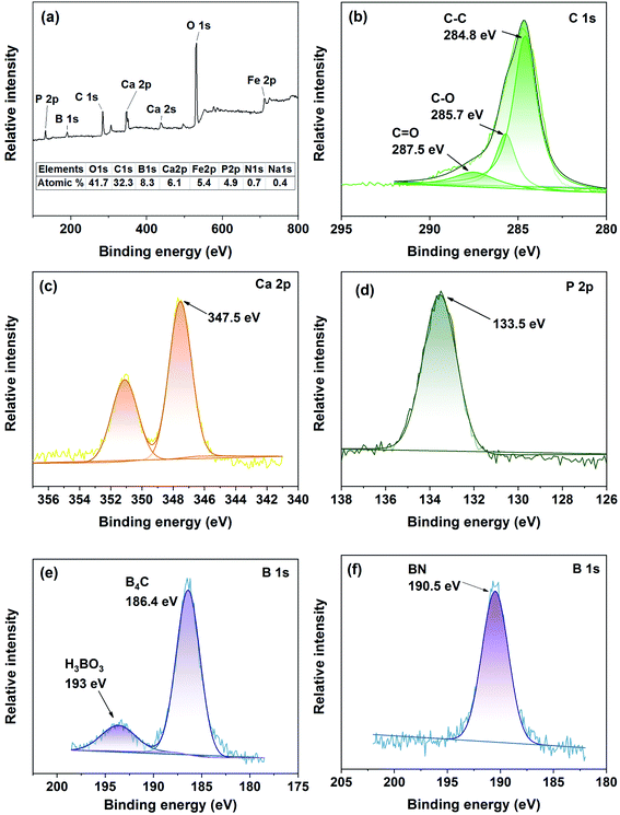
Fig. 9 illustrates XPS spectra of the steel surfaces rubbed in Hank's with PEEK/B4C and PEEK/BN, respectively. From the XPS survey spectrum of the steel surface rubbed PEEK/B4C, the peaks at around 133, 190, 284, 347, 531, and 711 eV correspond to the P 2p, B 1s, C 1s, Ca 2p, O 1s, and Fe 2p, as illustrated in Fig. 9a. Proportions of the main elements in the tribofilm were calculated according to areas of the peaks in high-resolution XPS spectra and are inserted in Fig. 9a. It is seen that the tribofilm contains significant fraction of element C, deriving from transfer of the polymer matrix. Moreover, abundant O, Ca and P elements are identified.
Fig. 9b illustrates the C 1s XPS spectrum on the metal surface rubbed with PEEK/B4C in Hank's. The peak at 287.5 eV corresponds to C![[double bond, length as m-dash]](https://www.rsc.org/images/entities/char_e001.gif) O indicating the existence of a ketone structure. The peak at 285.7 eV corresponds to C–O, which indicates the presence of an ether structure. The peak at 284.8 eV refers to the carbon skeleton. The above results corroborate transfer of PEEK matrix onto the metal counterface. From the B 1s spectrum illustrated in Fig. 9b, the peak at 193 eV is the characteristic peak of boric acid (H3BO3), indicating an occurrence of hydrolysis of B4C. That is, H3BO3 is generated due to the hydrolysis reaction of B4C particles exposed or/and released onto the friction interface. Besides, the peak at 186.4 eV is the fingerprint of B4C, indicating entrapment of B4C in the tribofilm.
O indicating the existence of a ketone structure. The peak at 285.7 eV corresponds to C–O, which indicates the presence of an ether structure. The peak at 284.8 eV refers to the carbon skeleton. The above results corroborate transfer of PEEK matrix onto the metal counterface. From the B 1s spectrum illustrated in Fig. 9b, the peak at 193 eV is the characteristic peak of boric acid (H3BO3), indicating an occurrence of hydrolysis of B4C. That is, H3BO3 is generated due to the hydrolysis reaction of B4C particles exposed or/and released onto the friction interface. Besides, the peak at 186.4 eV is the fingerprint of B4C, indicating entrapment of B4C in the tribofilm.
From Fig. 9c and d, strong peaks at 351 eV and 347.5 eV in the Ca 2p spectrum and the strong peak at 133.5 eV in the P 2p spectrum manifest the presence of significant calcium phosphates, referred hereafter as CaP. It should be pointed out that the notation “CaP” given here refers to multiple potential compounds of calcium phosphates since the accurate stoichiometric ratio and compositions of calcium phosphates cannot be determined. During the friction process, the ions in the electrolytes can be absorbed in the friction interface due to micro-galvanic cells which can attract the ions in the electrolytes.44 From the above results, among the various ions in Hank's, Ca2+ and phosphate ions play a crucial role in friction- and wear-reduction. It is assumed that the deposition of Ca2+ and phosphate ions on the metal surface improves the resilience of the tribofilm.
From the B 1s spectrum illustrated in Fig. 9e, the peak at 193 eV is the characteristic peak of boric acid (H3BO3), indicating an occurrence of hydrolysis of B4C. That is, H3BO3 is generated due to the hydrolysis reaction of B4C particles exposed or/and released onto the friction interface. Besides, the peak at 186.4 eV is the fingerprint of B4C, indicating entrapment of B4C in the tribofilm. Fig. 9f depicts the B 1s XPS spectrum of the metal surface rubbed with PEEK/BN in Hank's. The peak at 190.5 eV corresponds to B–N, verifying the transfer of BN onto the metal surface. Whereas, unlike PEEK/B4C, H3BO3 is not identified from the metal surface rubbed with PEEK/BN. It seems that the different tribological performance of PEEK/BN and PEEK/B4C can be related to possibly different hydrolysis efficiencies of BN and B4C. We assume that possibly higher hydrolysis efficiency of B4C than that of BN can account for the better tribological performance of PEEK/B4C being lubricated with aqueous mediums.
Hydrolysis occurs from the surface of B4C particles, and in consequence H3BO3 is generated at the friction interface under the action of rubbing stress. What's more, H3BO3 is easy to capture OH− to form [B(OH)4]− (ref. 45) according to eqn (1):
| H3BO3 + H2O = [B(OH)4]− + H+ | (1) |
Owing to the phosphate buffer pair in Hank's solution, the pH value of local area remains stable. Then, [B(OH)4]− groups attract Ca2+ ions through electrostatic force. At pH 7.4, phosphate ions are present as H2PO4− and HPO42−species. Ca2+ ions, combined with the surface [B(OH)4]− groups, attract negatively charged phosphate ions, i.e., H2PO4− and HPO42− from the solution. As a result, CaP is deposited on the steel surface with an anchoring effect of the [B(OH)4]− groups, as can be beneficial for the resilience of the tribofilm. Oyane et al.46 and Hayakawa et al.47 reported a similar deposition process of CaP onto metallic surfaces immersed in SBF.
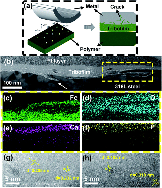
Fig. 10a illustrates the formation of the tribofilm with the participation of ions in the electrolytes. First, B4C is hydrolyzed triggered by the mechanical action. Meanwhile, Ca2+ and phosphate ions are absorbed into the friction interface. Finally, precipitated CaP mixed with PEEK fragments, the hydrolysate of B4C, and corrosion products of metal formed a tribofilm during the friction process. In order to shed light on nanostructures of the tribofilm growing on the metal surface rubbed with PEEK/B4C in Hank's, FIB-TEM analyses were conducted. As seen in Fig. 10b, a continuous tribofilm with an average thickness of about 80 nm grows from the metal surface. As indicated by the large white arrow in Fig. 10b, grooves formed probably due to corrosion were repaired by the tribofilm. EDS maps of Fe, O, Ca, and P elements of the squared zone in Fig. 10b are illustrated in Fig. 10c–f. It is apparent that the top layer of the tribofilm does not contain significant Fe. This gives a hint that after the running-in process the tribofilm separates direct rubbing between the friction pair and strengthens passivation of the metal. Nevertheless, under the top layer, a significant fraction of iron oxide is present in the tribofilm (cf. Fig. 10c and d). This indicates that before the formation of a stable tribofilm, the initial oxide film on the steel surface is damaged and corrosion of the metal surface occurs. Debris of the oxide film and the corrosion products were mixed and compacted with other ingredients of the tribofilm. EDS maps of P and Ca elements, as illustrated in Fig. 10e and f, gives direct evidence that Ca2+ and phosphate ions deposit from Hank's onto the metal surface, and thus plays an important role in tribofilm growth. It is reasonably assumed that the tribofilm containing the significant fraction of CaP possesses good biocompatibility.48 Fast Fourier transform (FFT) analyses corroborate presence of Cr2O3, B4C, Fe2O3, and H3BO3 in the tribofilm, which correspond respectively to lattice fringes of 0.205, 0.232, 0.192, and 0.319 nm. Close inspections demonstrate that the sizes of respective domains lie in the range of 2–20 nm.
3.3 Tribo-electrochemical performance
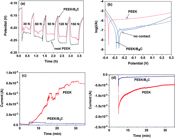
Fig. 11a depicts OCP of 316L stainless steel versus time recorded during intermittent sliding with neat PEEK and PEEK/B4C after 10 min stabilization in Hank's under loads ranging from 30 N to 150 N. It is clearly seen that with the onset of sliding, the OCP shifts to the cathodic direction abruptly due to damage of the passivation layer.49 During rubbing, the measured corrosion potential reflects the galvanic coupling of passive area and worn area. When the sliding was terminated after 30 min sliding, the OCP increased rapidly due to a re-passivation process of the worn area. An increment of the applied load shifts the OCP towards the cathodic direction. Under all loads concerned, OCP of 316L steel when being rubbed with PEEK/B4C is higher than that obtained when being rubbed with neat PEEK. These findings suggest that when being slid against PEEK/B4C, the passive film on the steel surface is less damaged in comparison to that on the steel surface slid against neat PEEK, and the steel shows a lower tendency to undergo tribo-corrosion. It is surmised that the addition of B4C into PEEK reduces wear of the steel surface.Fig. 11b compares potentiodynamic polarization curves of the stainless steel. Under contactless oscillation condition, the zero-current potential is about −0.25 V. When sliding takes place, the zero-current potential of the metal shifts cathodically due to mechanical abrasion on the metal surface. Nevertheless, in contrast to neat PEEK (−0.36 V), the zero-current potential of the metal is higher when being slid against PEEK/B4C (−0.28 V). Owing to the growth of a resilient tribofilm at the interface between the metal and PEEK/B4C, the metal shows lower susceptibility to corrosion when compared to that rubbed with neat PEEK.
Fig. 11c displays current transients of metal rubbed polymers under +0.3 V after 5 min stabilization. When metal is rubbed with neat PEEK, the onset of the sliding leads to the dramatic rise of the current. Then, the current increases over time due to cumulative damage of the passive film. In this case, fresh metal is exposed to the electrolyte and consequently, the metal is dissolved by anodic polarization, combined with increased roughness, causing aggravated corrosion and wear, i.e., tribocorrosion.19,50 With respect to the sliding against PEEK/B4C, the current increases moderately at the beginning of the sliding, and then it gradually decreases over time most probably due to the growth of a resilient tribofilm. Tribofilm formed on the steel surface rubbed with PEEK/B4C serves as a barrier between metal and electrolyte, and thus strengthens passivation.
Fig. 11d compares the currents of the steel slid against neat PEEK and PEEK/B4C under cathodic polarization. Similar to the tendency obtained under anodic polarization, currents of the steel being slid against PEEK-based materials rise sharply when the sliding takes place. Nevertheless, it is surprising that at the beginning stage of the sliding, the current is even higher than that obtained under anodic polarization. It is assumed that the oxide layer is reduced and thinned by cathodic polarization in the 5 min stabilization stage, thus the current rises very sharply once the sliding starts. However, the current decreases very rapidly, especially for the sliding with PEEK/B4C. On the one hand, adsorption of cations like Ca2+ in electrolyte on the cathode can decrease the current. On the other hand, growth of a tribofilm as a shielding layer decreases gradually the current. This is true especially for the sliding of PEEK/B4C because B4C exposed to the friction interface benefits tribofilm formation as described above. The protecting effect of the tribofilms forming in situ at the friction interface is thus corroborated.
Owing to the protection role of the tribofilm, direct rubbing between the PEEK/B4C with the steel surface is significantly mitigated. Thus, abrasion of the steel is reduced. What's more, passivation of the steel is strengthened thanks to the protection role of the tribo-products and hence corrosion of the steel is alleviated as well. Therefore, tribocorrosion of the steel rubbed with PEEK/B4C is reduced in comparison to that rubbed with PEEK.
To sum up, growth of a resilient tribofilm is important for improving at the same time wear and corrosion resistance polymer-on-metal pairs. Above results provides new ideas for greatly improving lifespan and reliability of not only polymer-on-metal artificial joints and but also engineering tribo-pairs via optimizing tribofilms' nanostructures. It should be noted that tribofilm growth is a rather complex process and is constantly fed by tribo-corrosion products of the friction pairs and by the corrosive mediums. We believe that it is a feasible to “tailor” tribofilm's structures and functionalities by formulating multifunctional polymer composites. When the functional species are released from the polymer matrices, they can influence physical and chemical actions at the friction interface and thus affect tribofilm formation.
4. Conclusions
In this work, tribocorrosion behaviors of PEEK-based materials rubbing with a stainless steel in NaCl, NaCl/Ca/P, and Hanks' solutions were comparatively studied. In particular, the tribofilms growing at friction interface were thoroughly characterized. Following conclusions can be drawn:● Adding a small amount of BN or B4C particles into PEEK reduces significantly the friction and wear. When sliding takes place in Hank's solution, the addition of only 1 vol% B4C improves the wear resistance of PEEK by nearly 20 times.
● In comparison to the sliding in 0.9% NaCl, the PEEK-based materials, i.e. neat PEEK, PEEK/BN, and PEEK/B4C, exhibit significantly lower wear when sliding takes place in NaCl/Ca/P and Hank's solutions.
● It is inferred that Ca2+ and PO43− ions in SBF plays a crucial lubrication role. Deposition of Ca2+ and PO43− ions from the electrolytes onto the steel surface helps formation of a protective tribofilm. It seems that interaction between the hydrolysis product of B4C, i.e. H3BO3, and CaP deposition is beneficial for enhancing the resilience of the tribofilm.
● The addition of B4C into PEEK significantly alleviates corrosion of the steel counterpart. The tribofilm formed on the steel surface rubbed with PEEK/B4C serves as a barrier between the metal and the electrolyte, and thus strengthens passivation.
Conflicts of interest
There are no conflicts to declare.Acknowledgements
The authors are grateful for financial support from National Key Research and Development Program of China (Grant No. 2018YFE0119300) and the National Natural Science Foundation of China (Grant No. 51905516, 51875552), as well as support of Belarus Fund of Fundamental Research (Project No. T20KITG-004).References
- Y. Ning, 7th Annually Meeting of Chinese Hip society, Zhengzhou, China, 2019 Search PubMed.
- A. Patel, G. Pavlou, R. E. Mujica-Mota and A. D. Toms, Bone Jt. J., 2015, 97-B, 1076–1081 CrossRef CAS PubMed.
- W. Zai, M. H. Wong and H. C. Man, Appl. Surf. Sci., 2019, 464, 404–411 CrossRef CAS.
- J. C. Keurentjes, R. M. Kuipers, D. J. Wever and B. W. Schreurs, Clin. Orthop. Relat. Res., 2008, 466, 1438–1443 CrossRef CAS PubMed.
- J. Nagels, M. Stokdijk and P. M. Rozing, J. Shoulder Elb. Surg, 2003, 12, 35–39 CrossRef PubMed.
- S. Limmahakhun, A. Oloyede, K. Sitthiseripratip, Y. Xiao and C. Yan, Mater. Des., 2017, 114, 633–641 CrossRef CAS.
- H. S. Hedia, S. M. Aldousari, H. A. Timraz and N. Fouda, Mater. Test., 2019, 61, 695–704 CAS.
- M. Stilling, I. Mechlenburg, C. F. Jepsen, L. Romer, O. Rahbek, K. Soballe and F. Madsen, Acta Orthop., 2019, 90, 165–171 CrossRef PubMed.
- R. Huiskes, H. Weinans and B. Vanrietbergen, Clin. Orthop. Relat. Res., 1992, 124–134 CAS.
- P. Bracco and E. Oral, Clin. Orthop. Relat. Res., 2011, 469, 2286–2293 CrossRef PubMed.
- J. Zeman, M. Ranusa, M. Vrbka, J. Gallo, I. Krupka and M. Hartl, J. Mech. Behav. Biomed. Mater., 2018, 87, 30–39 CrossRef CAS PubMed.
- P. F. Doorn, P. A. Campbell and H. C. Amstutz, Clin. Orthop. Relat. Res., 1996, S206–S216 CrossRef CAS PubMed.
- C. Y. Su, S. S. Huang and H. W. Fang, Polymers, 2018, 10, 635 CrossRef PubMed.
- J. Huang, L. Wang, B. Liu, S. Wan and Q. Xue, ACS Appl. Mater. Interfaces, 2015, 7, 2772–2783 CrossRef CAS PubMed.
- A. A. Stepashkin, D. I. Chukov, F. S. Senatov, A. I. Salimon, A. M. Korsunsky and S. D. Kaloshkin, Compos. Sci. Technol., 2018, 164, 319–326 CrossRef CAS.
- J. Song, D. Xiang, S. Wang, Z. Liao, J. Lu, Y. Liu, W. Liu and Z. Peng, Tribol. Int., 2018, 122, 218–227 CrossRef CAS.
- J. Song, F. Chen, Y. Liu, S. Wang, X. He, Z. Liao, X. Mu, M. Yang, W. Liu and Z. Peng, Tribol. Int., 2020, 144, 106093 CrossRef CAS.
- S. Bose, L. C. Pathak and R. Singh, Appl. Surf. Sci., 2018, 433, 1158–1174 CrossRef CAS.
- B. Stojanovic, C. Bauer, C. Stotter, T. Klestil, S. Nehrer, F. Franek and M. R. Ripoll, Acta Biomater., 2019, 94, 597–609 CrossRef CAS PubMed.
- A. I. Costa, L. Sousa, A. C. Alves and F. Toptan, Corros. Sci., 2020, 166, 108467 CrossRef CAS.
- M. Huber, G. Reinisch, G. Trettenhahn, K. Zweymuller and F. Lintner, Acta Biomater., 2009, 5, 172–180 CrossRef CAS PubMed.
- A. J. Hart, P. D. Quinn, F. Lali, B. Sampson, J. A. Skinner, J. J. Powell, J. Nolan, K. Tucker, S. Donell, A. Flanagan and J. F. W. Mosselmans, Acta Biomater., 2012, 8, 3865–3873 CrossRef CAS PubMed.
- G. B. Higgs, J. A. Hanzlik, D. W. MacDonald, J. L. Gilbert, C. M. Rimnac, S. M. Kurtz and C. Implant Research Center Writing, J. Arthroplasty, 2013, 28, 2–6 CrossRef PubMed.
- N. K. Myshkin, Wear, 2000, 245, 116–124 CrossRef CAS.
- P. Zeng, A. Rana, R. Thompson and W. M. Rainforth, Wear, 2015, 332–333, 650–661 CrossRef CAS.
- A. Fischer and S. Williams, in Encyclopedia of Tribology, ed. Q. J. Wang and Y.-W. Chung, Springer US, Boston, MA, 2013, pp. 3053–3063, DOI:10.1007/978-0-387-92897-5_1280.
- Y. Liao, R. Pourzal, M. A. Wimmer, J. J. Jacobs, A. Fischer and L. D. Marks, Science, 2011, 334, 1687–1690 CrossRef CAS PubMed.
- Y. Yan, A. Neville, D. Dowson, S. Williams and J. Fisher, Proc. Inst. Mech. Eng., Part J, 2010, 1, 1–10 Search PubMed.
- J. Hesketh, M. Ward, D. Dowson and A. Neville, Biomaterials, 2014, 35, 2113–2119 CrossRef CAS PubMed.
- M. T. Mathew, C. Nagelli, R. Pourzal, A. Fischer, M. P. Laurent, J. J. Jacobs and M. A. Wimmer, J. Mech. Behav. Biomed. Mater., 2014, 29, 199–212 CrossRef CAS PubMed.
- G. Liu, L. G. Zhang, G. T. Li, F. Y. Zhao, Q. L. Che, C. Wang and G. Zhang, Acta Biomater., 2019, 87, 285–295 CrossRef CAS PubMed.
- C. Gao, G. Guo, G. Zhang, Q. Wang, T. Wang and H. Wang, Mater. Des., 2017, 115, 276–286 CrossRef CAS.
- Y. Xu, Y. Guo, G. Li, L. Zhang, F. Zhao, X. Guo, A. I. Dmitriev and G. Zhang, Tribol. Int., 2018, 127, 147–156 CrossRef CAS.
- L. Zhang, H. Qi, G. Li, G. Zhang, T. Wang and Q. Wang, Tribol. Int., 2017, 109, 58–68 CrossRef CAS.
- J. Zhao and V. Castranova, J. Toxicol. Environ. Health, Part B, 2011, 14, 593–632 CAS.
- I. Dion, L. Bordenave, F. Lefebvre, R. Bareille, C. Baquey, J.-R. Monties and P. Havlik, J. Mater. Sci.: Mater. Med., 1994, 5, 18–24 CrossRef CAS.
- Y. Kimura, T. Wakabayashi, K. Okada, T. Wada and H. Nishikawa, Wear, 1999, 232, 199–206 CrossRef CAS.
- J. Bijwe, K. Kumar, J. N. Panda, T. Parida and P. Trivedi, Composites, Part B, 2016, 94, 399–410 CrossRef CAS.
- S. Sharma, J. Bijwe and S. Panier, Composites, Part B, 2016, 99, 312–320 CrossRef CAS.
- P. D. Cuong, H. S. Ahn, E. S. Yoon and K. H. Shin, Surf. Coat. Technol., 2006, 201, 4230–4235 CrossRef CAS.
- A. Unsworth, Proc. Inst. Mech. Eng., Part H, 1991, 205, 163–172 CrossRef CAS PubMed.
- B. J. Hamrock and D. Dowson, J. Lubr. Technol., 1978, 100, 236–245 CrossRef.
- Y. Xu, H. Qi, G. Li, X. Guo, Y. Wan and G. Zhang, J. Colloid Interface Sci., 2018, 518, 263–276 CrossRef CAS PubMed.
- Y. J. Yang, Z. P. Zhang, Z. S. Jin, W. C. Sun, C. Q. Xia, M. Z. Ma, X. Y. Zhang, G. Li and R. P. Liu, J. Alloys Compd., 2019, 782, 927–935 CrossRef CAS.
- N. Ingri, Acta Chem. Scand., 1962, 16, 439–448 CrossRef CAS.
- A. Oyane, M. Uchida, C. Choong, J. Triffitt, J. Jones and A. Ito, Biomaterials, 2005, 26, 2407–2413 CrossRef CAS PubMed.
- S. Hayakawa, K. Tsuru, C. Ohtsuki and A. Osaka, J. Am. Ceram. Soc., 1999, 82, 2155–2160 CrossRef CAS.
- A. R. Rafieerad, M. R. Ashra, R. Mahmoodian and A. R. Bushroa, Mater. Sci. Eng., C, 2015, 57, 397–413 CrossRef CAS PubMed.
- Y. Zhang, D. D. Macdonald, M. Urquidi-Macdonald, G. R. Engelhardt and R. B. Dooley, Corros. Sci., 2006, 48, 3812–3823 CrossRef CAS.
- A. R. Beadling, M. G. Bryant, D. Dowson and A. Neville, Tribol. Int., 2017, 113, 354–361 CrossRef CAS.
| This journal is © The Royal Society of Chemistry 2021 |

