 Open Access Article
Creative Commons Attribution 3.0 Unported Licence
The atomic-level structure of bandgap engineered double perovskite alloys Cs2AgIn1−xFexCl6†
Fuxiang
Ji
 a,
Feng
Wang
 a,
Libor
Kobera
 *b,
Sabina
Abbrent
 b,
Jiri
Brus
 b,
Weihua
Ning
 *ac and
Feng
Gao
 *a
*a
aDepartment of Physics, Chemistry and Biology (IFM), Linköping University, Linköping SE-581 83, Sweden. E-mail: weihua.ning@liu.se; feng.gao@liu.se
bInstitute of Macromolecular Chemistry of the Czech Academy of Sciences, Heyrovskeho nam. 2, 162 06, Prague 6, Czech Republic. E-mail: kobera@imc.cas.cz
cKey Laboratory of Flexible Electronics (KLOFE) and Institute of Advanced Materials (IAM), Nanjing Tech University, 30 South Puzhu Road, Nanjing 211816, P. R. China
First published on 8th December 2020
Abstract
Although lead-free halide double perovskites are considered as promising alternatives to lead halide perovskites for optoelectronic applications, state-of-the-art double perovskites are limited by their large bandgap. The doping/alloying strategy, key to bandgap engineering in traditional semiconductors, has also been employed to tune the bandgap of halide double perovskites. However, this strategy has yet to generate new double perovskites with suitable bandgaps for practical applications, partially due to the lack of fundamental understanding of how the doping/alloying affects the atomic-level structure. Here, we take the benchmark double perovskite Cs2AgInCl6 as an example to reveal the atomic-level structure of double perovskite alloys (DPAs) Cs2AgIn1−xFexCl6 (x = 0–1) by employing solid-state nuclear magnetic resonance (ssNMR). The presence of paramagnetic alloying ions (e.g. Fe3+ in this case) in double perovskites makes it possible to investigate the nuclear relaxation times, providing a straightforward approach to understand the distribution of paramagnetic alloying ions. Our results indicate that paramagnetic Fe3+ replaces diamagnetic In3+ in the Cs2AgInCl6 lattice with the formation of [FeCl6]3−·[AgCl6]5− domains, which show different sizes and distribution modes in different alloying ratios. This work provides new insights into the atomic-level structure of bandgap engineered DPAs, which is of critical significance in developing efficient optoelectronic/spintronic devices.
Introduction
Lead (Pb) halide perovskites have received considerable attention for photovoltaics field.1–3 However, the presence of toxic Pb and intrinsic poor stability are the main bottlenecks for their further application.4 A promising approach to solve these issues is to replace divalent Pb2+ with monovalent B+ and trivalent B3+ metal ions, forming a double perovskite with the formula of A2B+B3+X6 (A = Cs+, CH3NH3+; B = metal ions; X = Cl−, Br−, I−).5–7 Unfortunately, the large bandgaps of the current double perovskites limit their practical applications.Alloying/doping is a simple yet efficient method to tune the bandgaps of a wide range of materials, including traditional inorganic semiconductors,8,9 oxide-based perovskites,10 Pb-based perovskites,11 as well as lead-free halide double perovskites.12–15 For example, trivalent Sb3+-alloying has been employed to decrease the bandgap of Cs2AgBiBr6 and Cs2AgInCl6. However, the bandgaps of the alloys in both cases are still large for photovoltaic applications.12,13 In addition, multivalent Tl (Tl+/Tl3+) has also been introduced to decrease the bandgap of Cs2AgBiBr6 from 2.0 eV to 1.40 eV by Karunadasa and coworkers.14 Considering the high toxicity of Tl, they further doped less toxic Sn2+ into Cs2AgBiBr6 crystals, reaching a promising bandgap of 1.48 eV.15 However, the oxidatively unstable Sn2+ makes the doped perovskites highly sensitive to the ambient atmosphere. Therefore, finding rational alloying ions to tune the bandgaps of benchmark double perovskites remains challenging. During the preparation of this manuscript, Fe3+-alloying strategy was reported to reduce the bandgap of double perovskite Cs2AgInCl6.21
In parallel with the material development using the alloying strategy, fundamental understanding of these double perovskite alloys is also of critical importance. However, the atomic-level understanding of various dopants/alloys in halide DPAs is at a very early stage; recently, Michaelis and coworkers provided the first report for the long- to short-range structural elucidation of white-light-emitting DPAs.16 In this aspect, solid-state NMR (ssNMR), where very small chemical shifts within a given nucleus type record precisely the local chemical environment of its chemically inequivalent sites,17–20 provide a unique and powerful approach to understand the local atomic-level structures of double perovskite alloys.
Herein, we alloy magnetic ions (Fe3+-alloying) into the benchmark Cs2AgInCl6,21 and tune the bandgap of Cs2AgIn1−xFexCl6 over a range from 2.8 eV to 1.6 eV. We investigate the atomic-level structure of these double perovskite alloys using 133Cs and 115In ssNMR spectroscopy, where the paramagnetic Fe3+ provides rich information on nuclear relaxation times. We find that Fe3+ replaces In3+ in the Cs2AgIn1−xFexCl6 matrix, easily forming [FeCl6]3−·[AgCl6]5− domains. We also reveal that the sizes and distribution modes of [FeCl6]3−·[AgCl6]5− domains are different in different amounts of Fe3+ alloying. Our findings provide fundamental understanding of the atomic-level structure in double perovskite alloys, and are important for rational development of novel alloying elements for optoelectronic applications.
Results and discussion
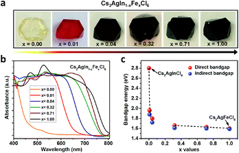
Double perovskite alloys (DPAs) Cs2AgIn1−xFexCl6 (x = 0–1) single crystals were synthesized by the hydrothermal method from CsCl, AgCl, InCl3, FeCl3 and HCl precursor solutions (more details in ESI†). As shown in Fig. 1a, all the resulting crystals exhibit similar truncated octahedral morphology, and the crystal color changes from transparent to black with increasing Fe3+ concentration. It is worth noting that the Fe3+ can completely substitute In3+ in Cs2AgInCl6 with the formation of Cs2AgFeCl6, probably due to comparable ion radii between In3+ and Fe3+.22 The accurate concentrations (x values) of Fe3+ in different crystals are obtained from inductively coupled plasma optical emission spectrometer (ICP-OES) (Table S1†).In order to understand different crystal colors between DPAs Cs2AgIn1−xFexCl6, we investigate their optical absorption properties through UV-Visible (UV-Vis) reflectance spectra (Fig. S1†), which are further transformed to pseudo-absorption values by the Kubelka–Munk theorem.23 As shown in Fig. 1b, there is a nonlinear change in the absorption for these alloys with increasing Fe3+ concentration. Specifically, the absorption edges broaden rapidly (from original ∼460 nm to ∼700 nm) with low Fe3+-concentrations (x ≤ 0.04) (Fig. 1b and S2†), consistent with the observed color changes in Fig. 1a. With increasing Fe3+ concentration, the absorption edges of Cs2AgIn1−xFexCl6 slowly broaden. We further determine the optical bandgaps of DPAs Cs2AgIn1−xFexCl6 (x = 0.00, 0.01, 0.04, 0.32, 0.71 and 1.00) by plotting αr as the function of photon energy (hν), where α is the pseudo-absorption coefficient, the values for r are 2 and 1/2 for a direct and indirect bandgap, respectively. Considering the uncertainty of the direct or indirect property of DPAs Cs2AgIn1−xFexCl6 (x > 0), we fit the absorption results by both functions (Fig. S3 and S4†). Both analyses indicate that the bandgap decreases quickly at low Fe3+-concentrations (x ≤ 0.04), followed by a slow decrease at high Fe-concentrations (x ≥ 0.32), reaching the smallest bandgap of ∼1.6 eV (Fig. 1c).
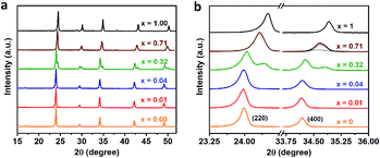
We further perform the powder X-ray diffraction (PXRD) measurements to investigate how Fe3+-alloying affects the crystal structures of DPAs Cs2AgIn1−xFexCl6. As shown in Fig. 2a, all patterns show a similar diffraction behavior for the entire 2θ range, indicating that all DPAs retain the original cubic structure of Cs2AgInCl6. Interestingly, the change of lattice parameters with increasing concentrations of Fe-alloying can be regarded as two stages (Fig. S5†), in accordance with the absorption results. For low Fe3+-concentrations (x ≤ 0.04), all the diffraction peaks are almost the same, with no obvious peak shifts (Fig. 2b). Further increasing the Fe3+-concentration (x ≥ 0.32), the diffraction peaks shift to the high-angle side gradually, which can be understood by the smaller ionic radius of Fe3+ (0.65 Å) compared with In3+ (0.80 Å). Particularly, both (220) and (400) diffraction peaks split into two peaks for 32% Fe3+-alloyed Cs2AgInCl6, suggesting the segregation of In3+-rich and Fe3+-rich phases. According to the Scherrer equation, we can estimate the average domain size of In3+-rich and Fe3+-rich phases are about 37 nm and 24 nm, respectively. These split diffraction peaks tend to merge into a single peak again with further increasing the Fe3+ concentration to 71% (Fig. 2b and S6†). In other words, the diffraction peaks split when the Fe3+ concentration is comparable with the In3+ concentration, implying possible formation of In3+-rich and Fe3+-rich phases, as confirmed by the following ssNMR measurements.
To investigate the distribution of different phases and atomic-level structures, we perform 133Cs, 115In solid-state NMR (ssNMR) experiments.16 As shown in Fig. 3, a relatively narrow, symmetric signal at ca. δiso = 41.6 ppm appears in pristine Cs2AgInCl6 in 115In ssNMR spectra which shifts slightly to lower frequencies with increasing concentrations of Fe. While these signals seem very similar, they contain useful structural information. We observe not only slight changes in the chemical shifts of the detected signal, but also signal broadening, suggesting increasing presence of dopant species (diamagnetic Fe2+/paramagnetic Fe3+) incorporated in the matrix. The increasing broadening of 115In signals with growing amount of Fe dopant species is induced by changes in static chemical disorder (distribution of local environments) as well as second order quadrupolar broadening of the central transition.16 In the case of 4% Fe-alloyed perovskite, the resulting 115In ssNMR spectrum shows broadened and less resolved spectral line (Fig. 3c and S7†). The increase of alloyed Fe concentration (32% and 71%) highlights this effect as recorded spectra become increasingly broad. This is further documented by increasing signal half-width in 115In ssNMR spectra (Fig. 3d and e), induced by the presence of Fe ions in the matrix.
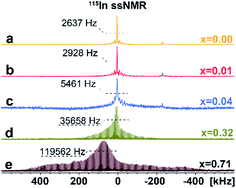 | ||
| Fig. 3 Experimental 115In ssNMR spin-echo (a–c) and WURST-QCPMG (d and e) spectra of Cs2AgIn1−xFexCl6 (x = 0.00, 0.01, 0.04, 0.32, 0.71), conducted at static conditions. The 115In WURST-QCPMG NMR spectra are shown for better clarity. The magnification of 115In ssNMR spin-echo spectra (a–c) and comparison of 115In ssNMR spectra (spin-echo vs. WURST-QCPMG) for (d and e) are listed in ESI, see Fig. S7 and S8,† respectively. | ||
Additional structural information is provided from 133Cs NMR spectra. As shown in Fig. 4a–f, the symmetric peak at δiso = 120.2 ± 0.5 ppm for pristine Cs2AgInCl6 splits, broadens and finally disappears with increasing concentration of Fe ions while at high concentrations a new peak at δiso = 2973 ± 1.0 ppm (Fig. 4d–f) grows. Single, narrow signals for the pristine Cs2AgInCl6 (Fig. 4a) and the completely substituted Cs2AgFeCl6 (Fig. 4f) confirm the existence of one crystallographic position of the Cs+ ions in both structures. The significant shift of peak from δiso = 120.2 ± 0.5 ppm (Cs2AgInCl6) to δiso = 2973 ± 1.0 ppm (Cs2AgFeCl6) in 133Cs MAS NMR spectra suggests presence of paramagnetic Fe3+ in perovskite matrix. Moreover, with increasing concentration of Fe ions alloyed into Cs2AgInCl6 lattice, the chemical environment of Cs+ becomes more complex as seen by additional signals appearing in the range of 100–120 ppm (Fig. S9†). Specifically, at low Fe concentration (x = 0.01), two signals are observed in the 133Cs MAS NMR spectra, first remaining at δiso = 120.2 ± 0.5 ppm and a new, less intensive peak appearing at δiso = 117.74 ± 0.5 ppm (Fig. 4b). As the Fe ion concentration increases (x ≥ 0.04), the latter signal becomes more significant. For 4% and 32% Fe alloyed systems, a third signal is resolved (Fig. 4c and d), at 111.0 ± 2.0 ppm. The second and third signal (δiso = 117.74 ± 0.5 ppm and 111.0 ± 2.0 ppm) suggest the presence of Fe ions located close to Cs ions. Furthermore, in cases of 32% and 71% Fe alloyed systems, the above mentioned new shifted signal(s) appear at low-frequency position of ca. 2950 ± 50 ppm (Fig. 4d and e). These new shifted signal(s) (δiso = 2950 ± 50, 2973 ± 1 and 3002 ± 1 ppm) seem to correspond to the splitting of peaks in the PXRD patterns (Fig. 2b and S6†). In addition, the small changes of 133Cs chemical shift in the diamagnetic region (ranging from 200 to (−100) ppm) can be explained by two ways: (i) through-space (pseudo-contact) interactions with paramagnetic Fe3+.24–26 and/or (ii) the diamagnetic effect of substitution and lattice contraction.16 The signals in the diamagnetic region as well as in paramagnetic spectral range around 2950 ppm, indicate multi-component nature of the DPAs, agreeing well with the PXRD results. Based on 115In and 133Cs ssNMR results, we conclude that the Fe3+ ions are incorporated into the matrix replacing In3+ ions.
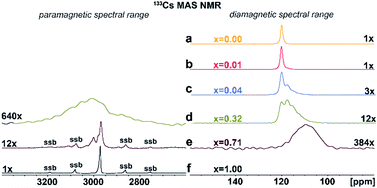 | ||
| Fig. 4 (a)–(f) Experimental 133Cs MAS NMR spectra of Cs2AgIn1−xFexCl6 (x = 0.00, 0.01, 0.04, 0.32, 0.71 and 1.00). The major detected 133Cs NMR signals were confirmed using 133Cs–133Cs SD/MAS NMR experiments (The 133Cs–133Cs SD/MAS NMR spectra are listed in ESI, Fig. S9†). | ||
To confirm the presence of paramagnetic Fe3+ ions and provide further information on their distribution in DPAs matrix, we perform 133Cs NMR T1-relaxation measurements.27,28 These are based on the fact that the presence of paramagnetic metal centers (e.g. Fe3+) usually causes extremely rapid longitudinal and transverse relaxation of the nearby nuclei due to electron-spin couplings. This approach was developed by Emsley and co-workers and it is based on the reduction of 1H and 133Cs NMR T1-relaxation times to detect paramagnetic dopants in lead halide perovskites.27,28 The saturation-recovery build–up curves of the detected 133Cs NMR signal(s) are analyzed by single and/or multi-exponential functions and values of T1 (133Cs) relaxation times as well as the corresponding fractions of individual components are obtained, see Table 1. Corresponding well with the symmetric single peaks of the Cs2AgInCl6 and Cs2AgFeCl6 systems in 133Cs MAS NMR spectra, the relaxation decays were fitted by a single exponential function. However, both systems provide significantly different relaxation times with a long T1 (133Cs) relaxation time of 100 s for Cs2AgInCl6 and a very short T1 (133Cs) relaxation time of 11 ms for Cs2AgFeCl6. These results further confirm one crystallographic position of the Cs+ ions in both systems in an altered unit cell.
| Materials | 133Cs δiso (ppm) | 133Cs T1a (s ms−1) | Rel. amount (%) |
|---|---|---|---|
| a The plots of the 133Cs T1 relaxation datasets with the fitted curves are depicted in ESI, see Fig. S10. b The 133Cs T1 relaxation time cannot be determined due to low concentration and poor resolution of 1D 133Cs MAS NMR spectrum (see Fig. 4d). | |||
| Cs2AgInCl6 | 120.2 ± 0.5 | 101 s | 100 |
| Cs2AgIn0.99Fe0.01Cl6 | 120.2 ± 0.5 | 7.7 s | 60 ± 10 |
| 117.7 ± 0.5 | 1.4 s | 40 ± 10 | |
| Cs2AgIn0.96Fe0.04Cl6 | 120.2 ± 0.5 | 420 ms | 50 ± 10 |
| 117.7 ± 0.5 | 63 ms | 25 ± 10 | |
| 111.0 ± 2.0 | 58 ms | 25 ± 10 | |
| Cs2AgIn0.68Fe0.32Cl6 | 120.2 ± 0.5 | 119 ms | 30 ± 10 |
| 117.7 ± 0.5 | 56 ms | 40 ± 10 | |
| 111.0 ± 2.0 | 34 ms | 30 ± 10 | |
| 2950 ± 50b | — | <5 ± 10 | |
| Cs2AgIn0.29Fe0.71Cl6 | 111.0 ± 2.0 | 1.2 s | 10 ± 10 |
| 2973 ± 1.0 | 8.4 ms | 60 ± 10 | |
| 3002 ± 1.0 | 7.2 ms | 30 ± 10 | |
| Cs2AgFeCl6 | 2973 ± 1.0 | 11 ms | 100 |
Contrary to the pristine materials, alloyed Cs2AgIn1−xFexCl6 systems exhibit multi-exponential behavior reflected by a dispersion of observed T1 (133Cs) relaxation times corresponding to distinct distributions of paramagnetic species in the matrix. The 1% Fe3+-alloyed Cs2AgInCl6 system is characterized by a double exponential decay with T1 (133Cs) relaxation times of 7.7 s (60%) and 1.4 s (40%), confirming a two-component character of the matrix. The rapid-relaxation (1.4 s) and the slow-relaxation phases (7.7 s) correspond to a phase extensively occupied by well-dispersed Fe3+ ions and the presence of Cs+ ions more distant from Fe3+ species, respectively. It is noted that the observed significant shortening of both T1 (133Cs) spin-lattice relaxation times as compared to the Cs2AgInCl6 parent system (100 s) indicates almost homogeneous distribution of Fe3+ ions (isolated [FeCl6]3− octahedrons and/or small [FeCl6]3−·[AgCl6]5− domains in size up to two unit cells) in the perovskite matrix. With increasing amount of alloyed Fe3+ ions (4% and 32%) in the matrix, the multi-component relaxation is further accelerated. The relaxation process is in range of tens and/or hundreds of milliseconds, representing 133Cs species in strong interaction with the dispersed Fe3+ ions. The significant shortening of relaxation times indicates presence of larger [FeCl6]3−·[AgCl6]5− domains, which mean that the [FeCl6]3−·[AgCl6]5− domains grow larger as the Fe3+-concentration increases.
Moreover, for the 4% Fe3+ alloyed perovskite, no signal at position 2950 ± 50 ppm was detected and a relatively long T1 relaxation time (420 ms) for signal at 120.2 ± 0.5 ppm was observed, which suggests the existence of large, homogeneously distributed [FeCl6]3−·[AgCl6]5− domains in Cs2AgInCl6 parent matrix. In contrast, a new and broad signal at 2950 ± 50 ppm observed for 32% Fe3+ alloyed perovskite system, points to formation of a secondary Fe3+-rich phase, also confirmed by observed very short relaxation times (120–30 ms). Besides, the visible broadening of the signal at 2950 ± 50 ppm indicates the presence of static disorder which implies random distribution of these [FeCl6]3−·[AgCl6]5− domains in the matrix. Combining the short relaxation times and additional peaks in 133Cs MAS NMR spectra (Table 1 and Fig. 4d), we can conclude that for 32% Fe3+ alloyed perovskite system the [FeCl6]3−·[AgCl6]5− domains have grown to form a second, interconnected microscopic phase (Fe3+-rich phase). These results correspond well with the feature in PXRD data, caused mainly by interconnection between these larger [FeCl6]3−·[AgCl6]5− domains.
In case of 71% Fe3+ alloyed system, we also conclude a two-component system based on 133Cs MAS NMR spectra (Fig. 4e) and T1 (133Cs) spin-lattice relaxation times. In 133Cs MAS NMR spectra, two relatively well-ordered phases of Cs2AgFeCl6 are confirmed by two sharp signals at 2973 and 3002 ppm while the [InCl6]3−·[AgCl6]5− domains are represented by the signal at 111.0 ± 2.0 ppm. The matrix can be defined as an inverted-phase system as compared to the above-mentioned systems. The distribution of [InCl6]3−·[AgCl6]5− domains can also be derived from the unexpectedly relatively long 133Cs T1 relaxation time (1.2 s, see Table 1.) of the corresponding signal. Considering that similarly long relaxation time was detected for the second phase of the 1% Fe alloyed Cs2AgInCl6, we conclude that the formation of relatively large [InCl6]3−·[AgCl6]5− domains surrounded by [FeCl6]3− matrix. Within these domains some substitution by Fe3+ ions can be presumed based on the value of the corresponding relaxation time. On the other hand, the very short relaxation times for the peaks at 2973 ± 1.0 and 3002 ± 1.0 ppm confirm formation of large [FeCl6]3−·[AgCl6]5− domains with slightly different local environments.
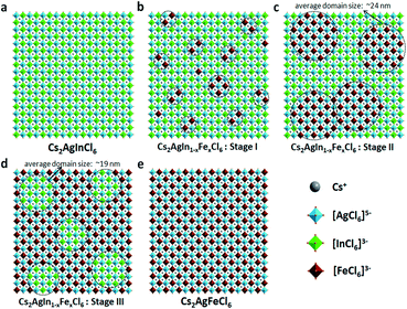
In short, based on the above observations, both pure Cs2AgInCl6 and Cs2AgFeCl6 are homogeneous systems (Fig. 5a and e). Meanwhile, the Fe-alloying process in DPAs Cs2AgIn1−xFexCl6 can be divided into the following three stages with different Fe3+ concentrations:
(i) For low Fe3+ concentration DPAs (x ≤ 0.04), Fe3+ ions exist in the form of isolated [FeCl6]3− octahedrons and/or small [FeCl6]3−·[AgCl6]5− domains, which are almost homogeneously distributed in the perovskite matrix (Fig. 5b, stage I).
(ii) For medium Fe3+ concentration DPAs, the isolated [FeCl6]3− octahedrons or small [FeCl6]3−·[AgCl6]5− domains grow into larger [FeCl6]3−·[AgCl6]5− domains. The growth of these domains forms microscopically segregated phases with different sizes, leading to nonhomogeneous distribution in the matrix (Fig. 5c, stage II). A typical example is DPAs Cs2AgIn1−xFexCl6 with 32% Fe3+ concentration. The average domain size of [FeCl6]3−·[AgCl6]5− domains in the 32% Fe3+ alloyed sample is about 24 nm.
(iii) For high Fe3+ concentration DPAs (x ≥ 0.71), the structure can be viewed as low concentration In3+-alloyed Cs2AgFeCl6. In this case, DPAs become a relatively uniform phase with almost homogeneous distribution of small and/or relatively large [InCl6]3−·[AgCl6]5− domains in the Cs2AgFeCl6 matrix (Fig. 5d, stage III).
Conclusions
In conclusion, we successfully tune the bandgap of Cs2AgInCl6 from 2.8 eV to 1.6 eV through Fe3+-alloying, which is attractive for optoelectronic device applications. Moreover, we provide fundamental understanding of the atomic-level structure of DPAs with paramagnetic alloying ions (Cs2AgIn1−xFexCl6), as revealed by the 133Cs/115In ssNMR spectroscopy. Our results indicate that paramagnetic Fe3+ replaces diamagnetic In3+ in Cs2AgIn1−xFexCl6 matrix and forms [FeCl6]3−·[AgCl6]5− domains, which grow larger as the Fe3+ concentration increases. Meanwhile, the connection of these larger [FeCl6]3−·[AgCl6]5− domains leads to the formation of microscopically segregated Fe3+-rich phases in DPAs. We believe that ssNMR is also widely suitable for atomic-level structure study in traditional magnetic semiconductors (e.g. GaAs![[thin space (1/6-em)]](https://www.rsc.org/images/entities/char_2009.gif) :
:![[thin space (1/6-em)]](https://www.rsc.org/images/entities/char_2009.gif) Mn), molecular magnets, etc.
Mn), molecular magnets, etc.
Conflicts of interest
There are no conflicts to declare.Acknowledgements
This work was financially supported by Knut and Alice Wallenberg Foundation, the Swedish Energy Agency (2018-004357), VR Starting Grant (2019–05279), Carl Tryggers Stiftelse, Olle Engkvist Byggmästare Stiftelse, the STINT grant (CH2018-7655), the National Natural Science Foundation of China (61704078), the Grant Agency of the Czech Republic (Grant GA19-05259S), and the Swedish Government Strategic Research Area in Materials Science on Functional Materials at Linköping University (Faculty Grant SFO-Mat-LiU No. 2009-00971). F. G. is a Wallenberg Academy Fellow. F. J. was supported by the China Scholarship Council (CSC).Notes and references
- A. Kojima, K. Teshima, Y. Shirai and T. Miyasaka, J. Am. Chem. Soc., 2009, 131, 6050–6051 CrossRef CAS.
- N. J. Jeon, J. H. Noh, W. S. Yang, Y. C. Kim, S. Ryu, J. Seo and S. I. Seok, Nature, 2015, 517, 476–480 CrossRef CAS PubMed.
- S. D. Stranks, G. E. Eperon, G. Grancini, C. Menelaou, M. J. P. Alcocer, T. Leijtens, L. M. Herz, A. Petrozza and H. J. Snaith, Science, 2013, 342, 341–344 CrossRef CAS PubMed.
- A. H. Slavney, R. W. Smaha, I. C. Smith, A. Jaffe, D. Umeyama and H. I. Karunadasa, Inorg. Chem., 2017, 56, 46–55 CrossRef CAS PubMed.
- A. H. Slavney, T. Hu, A. M. Lindenberg and H. I. Karunadasa, J. Am. Chem. Soc., 2016, 138, 2138–2141 CrossRef CAS PubMed.
- F. Ji, J. Klarbring, F. Wang, W. Ning, L. Wang, C. Yin, J. S. M. Figueroa, C. K. Christensen, M. Etter, T. Ederth, L. Sun, S. I. Simak, I. A. Abrikosov and F. Gao, Angew. Chem., 2020, 132, 15303–15306 CrossRef.
- J. Luo, X. Wang, S. Li, J. Liu, Y. Guo, G. Niu, L. Yao, Y. Fu, L. Gao, Q. Dong, C. Zhao, M. Leng, F. Ma, W. Liang, L. Wang, S. Jin, J. Han, L. Zhang, J. Etheridge, J. Wang, Y. Yan, E. H. Sargent and J. Tang, Nature, 2018, 563, 541–545 CrossRef CAS PubMed.
- K.-F. Berggren and B. E. Sernelius, Phys. Rev. B, 1981, 24, 1971–1986 CrossRef CAS.
- V. Palankovski, G. Kaiblinger-Grujin and S. Selberherr, Mater. Sci. Eng., B, 1999, 66, 46–49 CrossRef.
- R. Guo, R. Tian, D. Shi, H. Li and H. Liu, ACS Appl. Nano Mater., 2019, 2, 7755–7765 CrossRef CAS.
- F. Ji, L. Wang, S. Pang, P. Gao, H. Xu, G. Xie, J. Zhang and G. Cui, J. Mater. Chem. A, 2016, 4, 14437–14443 RSC.
- K. Du, W. Meng, X. Wang, Y. Yan and D. B. Mitzi, Angew. Chem., Int. Ed., 2017, 56, 8158–8162 CrossRef CAS.
- T. T. Tran, J. R. Panella, J. R. Chamorro, J. R. Morey and T. M. McQueen, Mater. Horiz., 2017, 4, 688–693 RSC.
- A. H. Slavney, L. Leppert, D. Bartesaghi, A. Gold-Parker, M. F. Toney, T. J. Savenije, J. B. Neaton and H. I. Karunadasa, J. Am. Chem. Soc., 2017, 139, 5015–5018 CrossRef CAS PubMed.
- K. P. Lindquist, S. A. Mack, A. H. Slavney, L. Leppert, A. Gold-Parker, J. F. Stebbins, A. Salleo, M. F. Toney, J. B. Neaton and H. I. Karunadasa, Chem. Sci., 2019, 10, 10620–10628 RSC.
- A. Karmakar, G. M. Bernard, A. Meldrum, A. O. Oliynyk and V. K. Michaelis, J. Am. Chem. Soc., 2020, 142, 10780–10793 CrossRef CAS PubMed.
- D. J. Kubicki, D. Prochowicz, E. Salager, A. Rakhmatullin, C. P. Grey, L. Emsley and S. D. Stranks, J. Am. Chem. Soc., 2020, 142, 7813–7826 CrossRef CAS PubMed.
- A. Q. Alanazi, D. J. Kubicki, D. Prochowicz, E. A. Alharbi, M. E. F. Bouduban, F. Jahanbakhshi, M. Mladenović, J. V. Milić, F. Giordano, D. Ren, A. Y. Alyamani, H. Albrithen, A. Albadri, M. H. Alotaibi, J.-E. Moser, S. M. Zakeeruddin, U. Rothlisberger, L. Emsley and M. Grätzel, J. Am. Chem. Soc., 2019, 141, 17659–17669 CrossRef CAS PubMed.
- D. J. Kubicki, D. Prochowicz, A. Hofstetter, P. Péchy, S. M. Zakeeruddin, M. Grätzel and L. Emsley, J. Am. Chem. Soc., 2017, 139, 10055–10061 CrossRef CAS PubMed.
- D. J. Kubicki, D. Prochowicz, A. Hofstetter, S. M. Zakeeruddin, M. Grätzel and L. Emsley, J. Am. Chem. Soc., 2017, 139, 14173–14180 CrossRef CAS PubMed.
- H. Yin, Y. Xian, Y. Zhang, W. Chen, X. Wen, N. U. Rahman, Y. Long, B. Jia, J. Fan and W. Li, Adv. Funct. Mater., 2020, 11 Search PubMed.
- W. Ning and F. Gao, Adv. Mater., 2019, 31, 1900326 CrossRef PubMed.
- P. Kubelka and F. Munk, Z. Tech. Phys., 1931, 12, 16 Search PubMed.
- Y. Ishii, N. P. Wickramasinghe and S. Chimon, J. Am. Chem. Soc., 2003, 125, 3438–3439 CrossRef CAS PubMed.
- R. J. Holmberg, T. Burns, S. M. Greer, L. Kobera, S. A. Stoian, I. Korobkov, S. Hill, D. L. Bryce, T. K. Woo and M. Murugesu, Chem.–Eur. J., 2016, 22, 7711–7715 CrossRef CAS PubMed.
- L. Kobera, S. Abbrent, L. Holcova, M. Urbanova, D. Kolousek, B. Dousova and J. Brus, Microporous Mesoporous Mater., 2017, 241, 115–122 CrossRef CAS.
- D. J. Kubicki, D. Prochowicz, A. Pinon, G. Stevanato, A. Hofstetter, S. M. Zakeeruddin, M. Grätzel and L. Emsley, J. Mater. Chem. A, 2019, 7, 2326–2333 RSC.
- W. Xiang, Z. Wang, D. J. Kubicki, W. Tress, J. Luo, D. Prochowicz, S. Akin, L. Emsley, J. Zhou, G. Dietler, M. Grätzel and A. Hagfeldt, Joule, 2019, 3, 205–214 CrossRef CAS.
Footnote |
| † Electronic supplementary information (ESI) available. See DOI: 10.1039/d0sc05264g |
| This journal is © The Royal Society of Chemistry 2021 |

