 Open Access Article
Carbon support tuned electrocatalytic activity of a single-site metal–organic framework toward the oxygen reduction reaction†
Wenjie
Ma
a,
Fei
Wu
a,
Ping
Yu
 ac and
Lanqun
Mao
 *ab
*ab
aBeijing National Laboratory for Molecular Sciences, Key Laboratory of Analytical Chemistry for Living Biosystems, Institute of Chemistry, The Chinese Academy of Sciences (CAS), Beijing 100190, China. E-mail: lqmao@iccas.ac.cn
bCollege of Chemistry, Beijing Normal University, Xinjiekouwai Street 19, Beijing 100875, China
cUniversity of Chinese Academy of Sciences, Beijing 100049, China
First published on 30th April 2021
Abstract
Metal–organic frameworks (MOFs) possess fantastic features such as structural diversity, tunable accessible pores and atomically dispersed active sites, holding tremendous potential as highly versatile platforms for fabricating single-site catalysts. The electrocatalytic activity of single-site MOFs can be improved and tuned via several approaches; however, the exploitation of different carbon supports to modulate the nature of single active sites in MOFs for electrocatalysis has not been reported. Here, we find that the electrocatalytic activity of single-site MOFs toward the oxygen reduction reaction (ORR) can be tuned by using carbon nanomaterials, i.e., carbon nanotubes and graphene, as supports through MOF–support interactions in the manner of geometric and electronic effects. The introduction of MOF–support interactions not only greatly improves the electrocatalytic performance of MOFs toward the ORR in terms of onset and half-wave potentials and current density, but also alters the reaction pathway of the ORR. This finding provides a new horizon for the design and synthesis of single-site MOFs for electrocatalysis.
Introduction
As an emerging class of periodically ordered porous crystalline materials, metal–organic frameworks (MOFs) have attracted extensive attention from interdisciplinary fields and been widely employed in a myriad of applications including gas storage and separation,1–3 optoelectronics, photovoltaics,4–6 sensing,7–10 biomedicine,11–14 catalysis,15–19 and energy storage and conversion,20–24 due to their excellent properties such as structural diversity, tunability and flexibility, and chemical tailorability. Moreover, atomically dispersed metal sites provide a versatile platform for the design and fabrication of MOF-based single-site catalysts,25–28 holding tremendous potential in the field of electrocatalysis from multiple perspectives: (1) abundant metal ions or clusters and ligands allow the design and synthesis of multifunctional MOFs for driving diverse reactions; (2) long-range ordered, tunable and accessible pores provide mass transport channels for electrolytes or reactants; (3) the well-aligned assemblies of organic linkers and inorganic nodes provide MOFs with distinct physiochemical properties unprecedented in conventional materials; (4) single active sites embedded in MOFs make it easier to tailor the electronic structures and investigate the catalytic mechanism.29–32 However, the poor electrical conductivity, blockade of single active sites by organic linkers and intrinsically high kinetic barriers impose great restrictions on the development of single-site MOFs for promoting electrochemical reactions.33,34The electrocatalytic activity of single-site MOFs is closely related to mass and charge transport efficiency, and accessibility of single catalytic sites as well as the chemical and electronic environment.35–37 So far, approaches reported to tune and improve the electrocatalytic activity of single-site MOFs have included: (a) tailoring three-dimensional (3D) MOFs into two-dimensional (2D) MOF nanosheets;38–40 (b) constructing continuous charge transport pathways through structural and chemical tuning of molecular building blocks in MOFs;41–43 (c) optimizing the unsaturated coordination environment via the introduction of defects or extra ligands.44–46 Through these approaches, the activity of single-site MOFs for catalyzing reactions such as the oxygen reduction reaction (ORR),47–50 hydrogen evolution reaction (HER),51–53 oxygen evolution reaction (OER)54,55 and CO2 reduction reaction (CO2RR)56–59 has been improved. For example, Dincă et al. designed and synthesized a conductive 2D MOF with an extended π-conjugated skeleton using 2,3,6,7,10,11-hexaiminotriphenylene as a multitopic ligand, exhibiting excellent electrocatalytic activity toward the ORR.60 Yaghi et al. reported a new 3D MOF constituted by cobalt phthalocyanin-2,3,9,10,16,17,23,24-octaol and Fe3(–C2O2–)6(OH2)2 clusters for electrochemical CO2RR with high current density, originating from the high charge transport efficiency of metal–catecholate linkages and electrochemically accessible molecular catalysts.61
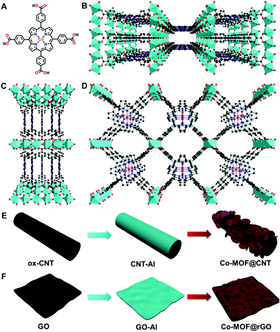
Besides the synthetic strategies, doping MOFs with conductive carbon nanomaterials has been recognized as another efficient approach to improve the electrocatalytic performance of MOFs, which was mainly attributed to the enhanced electroconductivity of the MOF–carbon nanocomposites.51,53,62 To the best of our knowledge, exploitation of the interactions between MOFs and carbon supports in a surface-confined manner to modulate the nature of single active sites for electrocatalysis has not been reported. In this study, we find that carbon supports can effectively tune the electrocatalytic activity of atomically dispersed active sites of MOFs toward the ORR through MOF–support interactions in the manner of geometric and electronic effects. To demonstrate this finding, an Al-carboxylate MOF (denoted as Co-MOF) comprising Al octahedral centers and cobalt meso-tetra(4-carboxylphenyl) porphyrin (Co-TCPP, Fig. 1A) linkers is used due to its chemical robustness and single catalytic sites (Fig. 1B–D).63 We find that, in addition to the roles of acting as supports for the synthesis of MOFs with different structures and orientations and in enhancing the electronic conductivity of MOFs, carbon materials including carbon nanotubes and graphene used here can influence the nature of atomically dispersed active sites in MOFs, thus altering the electrocatalytic pathway through MOF–support interactions. This finding opens a new avenue into the design and fabrication of single-site MOFs in electrocatalysis.
Results and discussion
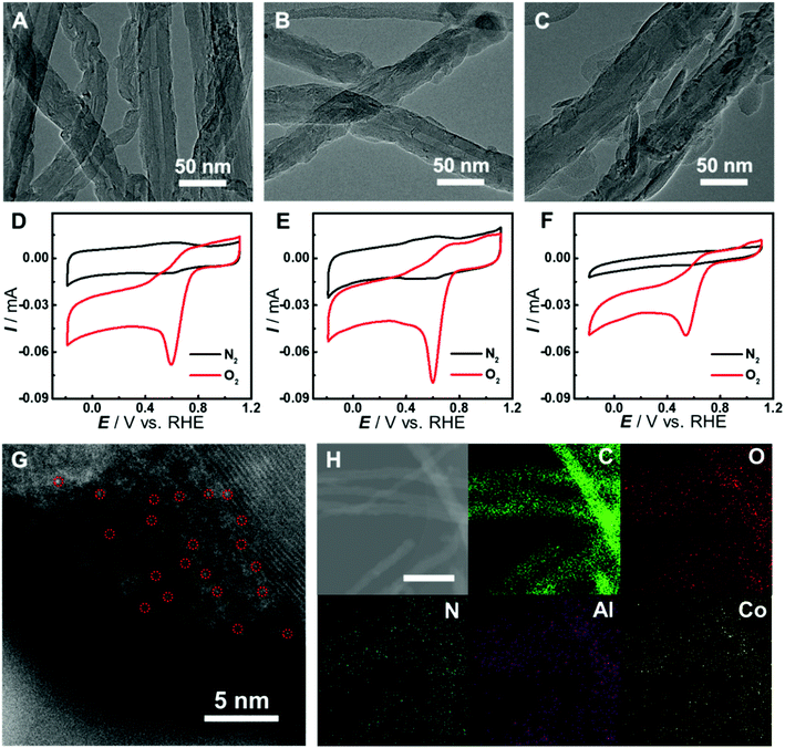
Although there have been several studies on combining the advantages of both carbon nanomaterials and MOFs for high-performance electrocatalysis, rationally designing and synthesizing heterostructures with efficient electron transfer remain challenging. In this study, an in situ growth method is developed to build the adequate contact, where an aluminum hydroxide layer is controllably deposited onto the surface of carbon nanomaterials and serves as a reservoir supplying metal ions to form a Co-MOF by coordinating with the Co-TCPP linker via microwave-assisted solvothermal synthesis (Fig. 1). In order to investigate the structurally and electronically tunable effects of carbon nanomaterials exerted on MOFs, two frequently used carbon nanomaterials, multi-walled carbon nanotubes (CNTs) and graphene are selected owing to their good electroconductivity, different dimensions and diverse electronic structures.As for CNT-supported Co-MOF (Co-MOF@CNT) catalysts, their fabrication started from the coating of the aluminum hydroxide precursor on CNTs, which was achieved and controlled by the reaction of Al2(SO4)3 with oxidized CNTs (ox-CNTs) in formic acid/ammonium formate buffered solution at 70 °C for 2 h. The aluminum layer deposited on CNTs was efficiently converted into Co-MOF in the presence of Co-TCPP linker under solvothermal conditions with the help of microwave heating at 140 °C for 1 h (Fig. 1E). The nucleation of the MOF occurs at the spots where aluminum hydroxide exists, enabling the tethering of the MOF on the surface of CNTs. In addition, by controlling the concentration of Al2(SO4)3, we could conveniently obtain CNTs with different coverages of the aluminum layer and MOF films. With this strategy, we were able to prepare MOF films with different thicknesses on CNT supports by using different amounts of Al2(SO4)3, which were termed Co-MOF@CNT-1, Co-MOF@CNT-2 and Co-MOF@CNT-3. The morphology of the nanocomposites was characterized by scanning electron microscopy (SEM) and transmission electron microscopy (TEM), showing that CNTs were uniformly sheathed with crystalline Co-MOF nanoplates (Fig. 2A–C, S1 and S2†). With increasing the concentration of Al2(SO4)3, the size of Co-MOF nanoplates and the thickness of the resulting MOF layer increase, validating such an in situ strategy for precisely controlling the coverage of the MOF on the CNT support.
To demonstrate the vital role of the in situ growth method in the fabrication of the CNT-supported Co-MOF, we prepared Co-MOF–CNT as a control catalyst by simple ultrasonic mixing of CNTs and the Co-MOF. Cyclic voltammetric (CV) measurements were conducted with glassy carbon (GC) electrodes modified with the catalysts as working electrodes in N2- or O2-saturated phosphate buffer (PB, pH 7.0) for the evaluation of the electrocatalytic activity toward the ORR. As shown in Fig. 2D–F and S3,† all three CNT-supported samples can catalyze the electroreduction of O2 efficiently with more positive peak potentials at 0.60 V, 0.60 V and 0.54 V (vs. the reversible hydrogen electrode, RHE), vastly outperforming Co-MOF (0.39 V) and Co-MOF–CNT (0.43 V). These results suggest the significance of the in situ growth strategy in fabricating CNT-supported MOF electrocatalysts with high performance. We have also found that, with the CNT-supported nanocomposites, the thickness of MOF films plays an important role in providing catalytic sites and affecting the transfer of electrons in heterostructures, thus determining the electrocatalytic performance toward the ORR. With the increase of MOF coverage, the peak potential keeps constant while the peak current increases from 56 μA of Co-MOF@CNT-1 to 71 μA of Co-MOF@CNT-2 (Fig. S3C†) due to the increased amount of active sites (Fig. 2A and B). However, if MOF coverage is further increased to a high level (Fig. 2C), the electrocatalytic activity (Fig. 2F and S3†) decreases in terms of negatively shifted peak potential (0.54 V) and decreased peak current (42 μA), mainly because the thick layer of the non-conductive MOF wrapped on CNT reduces the electroconductivity of the nanocomposite and blocks the electron transfer to the catalytic centers. Considering that the Co-MOF@CNT-2 showed the best electrocatalytic performance toward the ORR among the three samples, Co-MOF@CNT-2 was chosen for further investigations. To probe the atomic dispersion of Co in Co-MOF@CNT-2, aberration-corrected high-angle annular dark-field imaging scanning TEM (HAADF-STEM) was performed. As shown in Fig. 2G, the isolated bright dots marked with red circles are recognized to be Co atoms, indicating that Co atoms exist as an isolated atomic form in Co-MOF@CNT-2. The elemental mapping images with energy-dispersive X-ray spectrometry (EDS) suggest the uniform distribution of Co-MOF nanoplates on the support surface for Co-MOF@CNT-2 (Fig. 2H).
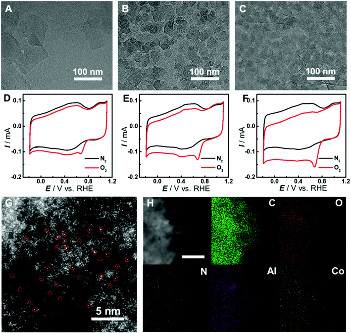
The synthesis of graphene-supported Co-MOF catalysts involved the controllable coating of the aluminum hydroxide layer onto the surface of graphene oxide (GO) by stirring the mixture of Al2(SO4)3, urea and GO at 90 °C for 3 h, and the in situ nucleation of the MOF together with the reduction of GO to form reduced GO-supported Co-MOF (Co-MOF@rGO) under microwave heating (Fig. 1F). Accordingly, four samples with different coverages of the Co-MOF named Co-MOF@rGO-1, Co-MOF@rGO-2, Co-MOF@rGO-3 and Co-MOF@rGO-4 were obtained by controlling the concentrations of Al2(SO4)3 and urea, all displaying the morphology of crystalline Co-MOF nanoplates uniformly stacked on the surface of the graphene nanosheet (Fig. 3A–C, S4 and S5†). The coverage of Co-MOF nanoplates coated on graphene increases with increasing the concentrations of the precursors. Meanwhile, the size of Co-MOF nanoplates decreases from 99 nm for Co-MOF@rGO-1 to 30 nm for Co-MOF@rGO-2 and 20 nm for Co-MOF@rGO-3 (Fig. S6A–C†). When further increasing the concentration of the precursors, the coverage and size of Co-MOF nanoplates remain unchanged (Fig. S4G, H, S5G, H and S6D†).
In consideration of the structural distinction of Co-MOF@rGO samples, we proceeded to assess their electrocatalytic activity toward the ORR by CV measurements. As shown in Fig. 3D–F and S7,† the graphene-supported MOF nanocomposites can all efficiently catalyze the ORR with similar peak potentials around 0.67 V, indicating that the atomically dispersed active sites in the four samples exhibit similar electrocatalytic activity toward the ORR. The peak potential is much higher than those of Co-MOF (0.39 V) and Co-MOF–rGO (0.52 V) prepared by simple mixing of rGO and Co-MOF under sonication (Fig. S7D†), demonstrating that the in situ growth method developed here is essential to achieve high electron transfer efficiency between graphene and Co-MOF nanoplates. With increasing MOF coverage on graphene, the peak current increases from 56 μA of Co-MOF@rGO-1 to 72 μA of Co-MOF@rGO-2 and 104 μA of Co-MOF@rGO-3 (Fig. S7C†). Co-MOF@rGO-4 exhibits similar electrocatalytic activity in terms of peak current of 101 μA to Co-MOF@rGO-3 due to their similar MOF coverage, as shown in TEM images. Given the excellent electrocatalytic performance toward the ORR among the graphene-supported samples, Co-MOF@rGO-3 was selected for following investigations. The atomic dispersion of Co in Co-MOF@rGO-3 was also confirmed by HAADF-STEM. Obvious bright dots were observed and identified as isolated Co atoms in Co-MOF@rGO-3 (Fig. 3G). In addition, the EDS mapping images demonstrated the uniform growth of Co-MOF nanoplates on graphene (Fig. 3H).
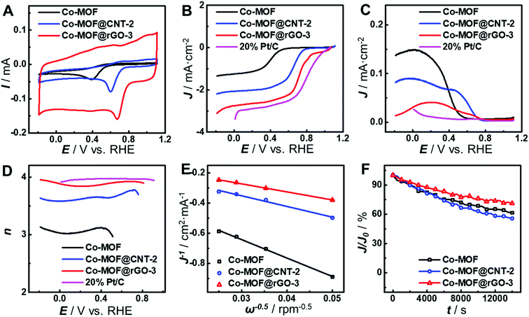
As can be seen from Fig. 4A, the carbon supports greatly improve the electrocatalytic activity of the as-developed Co-MOF toward the ORR in terms of peak potential and peak current, indicating the vital role of carbon supports. Compared with that at the pristine Co-MOF, the peak potentials of the ORR at Co-MOF@CNT-2 and Co-MOF@rGO-3 positively shift by 0.21 V and 0.28 V, respectively, and the peak currents increase by 1.8-fold and 2.6-fold, respectively. These results provide a direct demonstration of different impacts of carbon supports on the electrocatalytic performance of the surface-grown MOF. In order to further study the improvement in the electrocatalytic activity of surface-grown MOFs, rotating ring-disk electrode (RRDE) voltammetry was carried out. As shown in Fig. 4B, the half-wave potential of the ORR at Co-MOF@rGO-3 locates at 0.74 V (vs. RHE), which is more positive than those at Co-MOF@CNT-2 (0.65 V) and the Co-MOF (0.40 V) and close to that at 20% Pt/C (0.83 V). Moreover, Co-MOF@rGO-3 exhibits the lowest ring current generated by the oxidation of H2O2 concurrently produced during the ORR on the disk electrode (Fig. 4C). The electron transfer number (n) of the ORR at Co-MOF@rGO-3 evaluated from the RRDE data is over 3.9 in the potential range of 0.50–0.80 V (Fig. 4D), which is comparable to the result at 20% Pt/C, indicating that the ORR catalyzed by Co-MOF@rGO-3 follows a four-electron reduction pathway. The value of n was also calculated from Koutecky–Levich plots (Fig. 4E and S8†) to be 1.75, 3.02, and 4.00 for Co-MOF, Co-MOF@CNT-2 and Co-MOF@rGO-3, respectively, suggesting that the support effect can alter the catalytic mechanism of the MOF toward the ORR from the two-electron reduction pathway at the Co-MOF to the four-electron reduction pathway at Co-MOF@rGO-3. The long-term stability of the catalysts was evaluated by chronopotentiometric measurements to verify different carbon support effects. As shown in Fig. 4F and S9,† the catalytic current decreases the least at the Co-MOF@rGO-3-modified electrode after 4 h ORR durability evaluation, indicating that the fabrication of the MOF on graphene greatly enhances the stability of the MOF during electrocatalysis, as compared with that on CNTs. In addition, no obvious changes of the morphology and component are observed in SEM or TEM images of the surface-grown catalysts after the 4 h ORR test (Fig. S10 and S11†), confirming the stability of the catalysts.
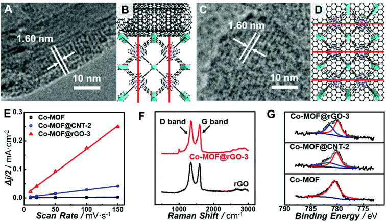
All the observations above demonstrate that in situ growth of the Co-MOF on CNTs and graphene can greatly improve the electrocatalytic activity of the Co-MOF toward the ORR. However, CNTs and graphene exhibit different support effects on modulating the nature of the atomically dispersed active sites in the Co-MOF. In order to unravel the origin of the different MOF–support interactions, characterization of the chemical and electronic structures of the carbon-supported Co-MOF was carried out. All the prepared catalysts show the same diffraction peaks from powder X-ray diffraction (PXRD) patterns (Fig. S12†), indicating the same structure and high crystallinity of MOF in the nanocomposites. Analysis of the nitrogen sorption isotherm (Fig. S13†) for Co-MOF@rGO-3 afforded the Brunauer–Emmett–Teller (BET) surface area of 497.7 m2 g−1, which is higher than those of the Co-MOF (436.6 m2 g−1) and Co-MOF@CNT-2 (383.6 m2 g−1). The higher surface area is beneficial to the mass transport of the electrolytes and reactants, thus resulting in better electrocatalytic performance. High-resolution TEM (HR-TEM) was performed to reveal the geometric interactions between carbon supports and the Co-MOF. As shown in Fig. 5A and C, lattice fringes of 1.60 nm corresponding to the (200) planes of the Co-MOF were observed for both CNT- and graphene-supported nanocomposites, confirming the high crystallinity of the Co-MOF on carbon supports.64 Nevertheless, CNTs and graphene exhibit different geometric effects on the growth of Co-MOF nanoplates, leading to different preferred orientations of Co-MOF nanoplates enclosing on the supports. It was unfavorable for the 2D layer of the Co-MOF composed of porphyrin linkers to wrap the curved surface of CNTs, resulting in the growth of the porphyrin layer along the direction perpendicular to the CNT surface (Fig. 5B). In sharp contrast, Co-MOF nanoplates tended to stack on graphene with the planar porphyrin layer parallel to the graphene surface (Fig. 5D). The growth orientation of the Co-MOF has a great influence on the electron transfer from carbon supports to the atomically dispersed active sites of the Co-MOF. For Co-MOF@CNT-2, the electron transfer from CNTs to the active centers could be partially blocked due to the semi-conductivity of the Co-MOF. However for Co-MOF@rGO-3, the strong π–π stacking between porphyrin units and graphene promoted the electron transfer from graphene to the active sites of the Co-MOF.
To further understand the support effects of CNTs and graphene on the electocatalytic activity of the Co-MOF, the double-layer capacitance (Cdl) of the electrodes was determined from CV measurements in the potential range where no redox reactions occurred (Fig. S14†). Cdl of Co-MOF@rGO-3 was calculated to be 0.41 mF cm−2 μg, which is 6.2 times and 100 times the values of Co-MOF@CNT-2 (6.6 × 10⁻² mF cm−2 μg) and Co-MOF (4.1 × 10⁻³ mF cm−2 μg), respectively (Fig. 5E). Although CNTs and graphene are both excellent electron conductors, there still exists significant difference in Cdl between Co-MOF@CNT-2 and Co-MOF@rGO-3, originating from the different growth orientation of the Co-MOF on graphene and CNTs. As for Co-MOF@rGO-3, the ultrathin graphene-supported Co-MOF nanocomposites with the thickness of around 5 nm (Fig. S15†) and the strong π–π stacking interaction contribute to the formation of 3D electroconductive networks with a higher ECSA compared with Co-MOF@CNT-2, to some extent explaining the distinct electrocatalytic performance especially the higher current density of Co-MOF@rGO-3.
In addition, Raman spectroscopy and X-ray photoelectron spectroscopy (XPS) were conducted to further investigate the electronic MOF–support interaction. As shown in Fig. 5F, after the growth of the Co-MOF onto the surface of graphene, the intensity ratio of the D-band to G-band (ID/IG) increases from 1.03 of rGO to 1.11 of Co-MOF@rGO-3, while the ID/IG ratio increases from 0.71 of the CNT to 0.73 of Co-MOF@CNT-2 (Fig. S16†), indicating a higher degree of the covalent connection between Co-MOF nanoplates and graphene.65 The strong covalent connection enables the supports to stabilize the Co-MOF nanoplates and modulate the electronic structures of the atomically dispersed active sites, which are critical for the electrocatalytic activity toward the ORR. Fig. 5G displays the high-resolution Co 2p XPS spectra of the Co-MOF, Co-MOF@CNT-2 and Co-MOF@rGO-3. The Co-MOF exhibits the peak located at 780.5 eV for the Co2+ in the CoTCPP linker. In addition to the Co2+ peaks at 780.2 eV for Co-MOF@CNT-2 and 780.1 eV for Co-MOF@rGO-3, new peaks located at 781.4 eV for Co-MOF@CNT-2 and 781.5 eV for Co-MOF@rGO-3 were also observed, suggesting Co with a higher oxidation state arises after the tethering of Co-MOF nanoplates on CNTs and graphene. The percentages of Co with a higher oxidation state in Co-MOF@CNT-2 and Co-MOF@rGO-3 were calculated to be 28.7% and 39.1%, respectively, indicating that more electron delocalization occurred from Co centers to graphene. The electron delocalization can induce the redistribution of electrons at the active Co site, enabling it with optimal bond strength for the adsorption and desorption of oxygen-related species involved in electrocatalytic ORR.66 As graphene holds stronger geometric and electronic MOF–support interactions than CNTs, the atomically dispersed Co sites in Co-MOF@rGO-3 exhibit a greater degree of electron delocalization, endowing the graphene-supported Co-MOF with much enhanced electrocatalytic activity.
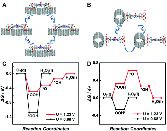
To further elucidate the different support effects of graphene and CNTs on the electrocatalytic activity of atomically dispersed active sites in MOFs, density functional theory (DFT) simulations were conducted. The ORR through the 4e− pathway is composed of four proton-coupled electron transfer processes involving the sequential reductions of O2 to *OOH, *OH, *O and H2O (the asterisk (*) represents the active site of the catalyst), as shown in Fig. 6A. In contrast, the 2e− ORR includes two proton-coupled electron transfer steps with the generation of a single OOH* intermediate (Fig. 6B). The reduction of O2via the 4e− or 2e− pathway is mainly determined by the kinetic barrier for the reduction of *OOH to *O and *OH or *OOH dissociation. Thus, the adsorption energies of oxygenated intermediates on the single active site in graphene or CNT-supported CoP-MOFs at the equilibrium potentials (U = 1.23 V for 4e− ORR and U = 0.68 V for 2e− ORR, respectively) were calculated. As displayed in Fig. 6C and D, the *OOH dissociation is the rate-determining step (RDS) for the 2e− ORR at both supported catalysts. The formation of *OH is the RDS for the 4e− ORR at the graphene-supported Co-MOF, while the formation of *OOH is the RDS for the 4e− ORR at the CNT-supported Co-MOF. Moreover, the theoretical overpotentials of the 2e− and 4e− ORR on the supported single-site catalysts were obtained from the free energy diagram (Fig. S17†) and are summarized in Fig. S18.† Obviously, the CNT-supported Co-MOF possesses a higher theoretical overpotential (0.33 V) than the graphene-supported Co-MOF (0.18 V) for the 4e− ORR, whereas the theoretical overpotential at the CNT-supported Co-MOF (0.26 V) is much lower than that of the graphene-supported Co-MOF (1.07 V) for the 2e− ORR, indicating that the 4e− ORR is energetically preferred at the single Co sites in the graphene-supported Co-MOF, while the CNT-supported Co-MOF is more likely to catalyze the 2e− ORR.
Conclusions
In summary, we have demonstrated that the electrocatalytic activity of the atomically dispersed active sites in MOFs can be tuned by using carbon supports via geometric and electronic MOF–support interactions. Different carbon supports (i.e., CNTs and graphene) result in the growth of MOFs with different surface orientations, further leading to different electroconductivities and electronic effects. The stacking of Co-MOF nanoplates on graphene greatly improves the electrocatalytic performance toward the ORR in terms of a lower overpotential. More importantly, the electrocatalytic mechanism of the ORR can be altered from the two-electron reduction pathway of a pristine Co-MOF to the four-electron reduction pathway of the graphene-supported Co-MOF. We believe this work will provide a facile synthetic strategy for the fabrication of electronically conductive MOFs, opening up a new avenue for the tuning of electrocatalytic activity of single-site MOFs via MOF–support interactions.Author contributions
W. M. and L. M. conceived the idea for the project. W. M. conducted all the experiments including material synthesis, structural characterization and electrochemical measurements. P. Y. contributed to the discussion of the electrocatalysis part. W. M. and F. W drafted the manuscript, and L. M. finalized the manuscript. All authors discussed and commented on the manuscript.Conflicts of interest
There are no conflicts to declare.Acknowledgements
We acknowledge financial support from the National Key Research and Development Program (2018YFE0200800), the National Natural Science Foundation of China (Grant No. 21790390 and 21790391 for L. M., 21705155 and 21790392 for W. M., 21874139 and 21927804 for F. W., and 21775151 and 21790053 for P. Y.), the National Basic Research Program of China (2016YFA0200104 and 2018YFA0703501), the Strategic Priority Research Program of Chinese Academy of Sciences (XDB30000000), the Chinese Academy of Sciences (QYZDJSSW-SLH030), and the Young Elite Scientist Sponsorship Program of Beijing Association for Science and Technology (2021–2023).Notes and references
- X. Han, S. Yang and M. Schröder, Nat. Rev. Chem., 2019, 3, 108–118 CrossRef CAS.
- Q. Qian, P. A. Asinger, M. J. Lee, G. Han, K. M. Rodriguez, S. Lin, F. M. Benedetti, A. X. Wu, W. S. Chi and Z. P. Smith, Chem. Rev., 2020, 120, 8161–8266 CrossRef CAS PubMed.
- Z. M. Schulte, Y. H. Kwon, Y. Han, C. Liu, L. Li, Y. Yang, A. G. Jarvi, S. Saxena, G. Veser, J. K. Johnson and N. L. Rosi, Chem. Sci., 2020, 11, 12807–12815 RSC.
- Y. Jiang, W. Ma, Y. Qiao, Y. Xue, J. Lu, J. Gao, N. Liu, F. Wu, P. Yu, L. Jiang and L. Mao, Angew. Chem., Int. Ed., 2020, 59, 12795–12799 CrossRef CAS.
- R. Dong, P. Han, H. Arora, M. Ballabio, M. Karakus, Z. Zhang, C. Shekhar, P. Adler, P. S. Petkov, A. Erbe, S. C. B. Mannsfeld, C. Felser, T. Heine, M. Bonn, X. Feng and E. Cánovas, Nat. Mater., 2018, 17, 1027–1032 CrossRef CAS PubMed.
- R. A. Fritz, Y. J. Colón and F. Herrera, Chem. Sci., 2021, 12, 3475–3482 RSC.
- W. Ma, Q. Jiang, P. Yu, L. Yang and L. Mao, Anal. Chem., 2013, 85, 7550–7557 CrossRef CAS.
- K. Roztocki, F. Formalik, A. Krawczuk, I. Senkovska, B. Kuchta, S. Kaskel and D. Matoga, Angew. Chem., Int. Ed., 2020, 59, 4491–4497 CrossRef CAS.
- M. L. Aubrey, M. T. Kapelewski, J. F. Melville, J. Oktawiec, D. Presti, L. Gagliardi and J. R. Long, J. Am. Chem. Soc., 2019, 141, 5005–5013 CrossRef CAS.
- B. Wang, P. Wang, L.-H. Xie, R.-B. Lin, J. Lv, J.-R. Li and B. Chen, Nat. Commun., 2019, 10, 3861 CrossRef.
- T. Simon-Yarza, A. Mielcarek, P. Couvreur and C. Serre, Adv. Mater., 2018, 30, 1707365 CrossRef.
- R. V. Pinto, S. Wang, S. R. Tavares, J. Pires, F. Antunes, A. Vimont, G. Clet, M. Daturi, G. Maurin, C. Serre and M. L. Pinto, Angew. Chem., Int. Ed., 2020, 59, 5135–5143 CrossRef CAS PubMed.
- Y. Sang, F. Cao, W. Li, L. Zhang, Y. You, Q. Deng, K. Dong, J. Ren and X. Qu, J. Am. Chem. Soc., 2020, 142, 5177–5183 CrossRef CAS PubMed.
- P. Li, J. Li, X. Feng, J. Li, Y. Hao, J. Zhang, H. Wang, A. Yin, J. Zhou, X. Ma and B. Wang, Nat. Commun., 2019, 10, 2177 CrossRef PubMed.
- A. Bavykina, N. Kolobov, I. S. Khan, J. A. Bau, A. Ramirez and J. Gascon, Chem. Rev., 2020, 120, 8468–8535 CrossRef CAS.
- Q. Wang and D. Astruc, Chem. Rev., 2020, 120, 1438–1511 CrossRef CAS.
- Z. Li, Y. Chen, S. Ji, Y. Tang, W. Chen, A. Li, J. Zhao, Y. Xiong, Y. Wu, Y. Gong, T. Yao, W. Liu, L. Zheng, J. Dong, Y. Wang, Z. Zhuang, W. Xing, C.-T. He, C. Peng, W.-C. Cheong, Q. Li, M. Zhang, Z. Chen, N. Fu, X. Gao, W. Zhu, J. Wan, J. Zhang, L. Gu, S. Wei, P. Hu, J. Luo, J. Li, C. Chen, Q. Peng, X. Duan, Y. Huang, X.-M. Chen, D. Wang and Y. Li, Nat. Chem., 2020, 12, 764–772 CrossRef CAS.
- L. Chen and Q. Xu, Matter, 2019, 1, 57–89 CrossRef.
- J. Canivet, E. Bernoud, J. Bonnefoy, A. Legrand, T. K. Todorova, E. A. Quadrelli and C. Mellot-Draznieks, Chem. Sci., 2020, 11, 8800–8808 RSC.
- L. Jiao and H.-L. Jiang, Chem, 2019, 5, 786–804 CAS.
- M. Ding, R. W. Flaig, H.-L. Jiang and O. M. Yaghi, Chem. Soc. Rev., 2019, 48, 2783–2828 RSC.
- W. Xiong, X. Cheng, T. Wang, Y. Luo, J. Feng, S. Lu, A. M. Asiri, W. Li, Z. Jiang and X. Sun, Nano Res., 2020, 13, 1008–1012 CrossRef CAS.
- Y. T. Guntern, J. R. Pankhurst, J. Vávra, M. Mensi, V. Mantella, P. Schouwink and R. Buonsanti, Angew. Chem., Int. Ed., 2019, 58, 12632–12639 CrossRef CAS.
- Q. Jiang, P. Xiong, J. Liu, Z. Xie, Q. Wang, X.-Q. Yang, E. Hu, Y. Cao, J. Sun, Y. Xu and L. Chen, Angew. Chem., Int. Ed., 2020, 59, 5273–5277 CrossRef CAS.
- T. Sun, L. Xu, D. Wang and Y. Li, Nano Res., 2019, 12, 2067–2080 CrossRef CAS.
- E. M. Miner, L. Wang and M. Dincă, Chem. Sci., 2018, 9, 6286–6291 RSC.
- Y.-S. Wei, M. Zhang, R. Zou and Q. Xu, Chem. Rev., 2020, 120, 12089–12174 CrossRef CAS PubMed.
- S. Yang, J. Zhang, L. Peng, M. Asgari, D. Stoian, I. Kochetygov, W. Luo, E. Oveisi, O. Trukhina, A. H. Clark, D. T. Sun and W. L. Queen, Chem. Sci., 2020, 11, 10991–10997 RSC.
- X. Xiao, L. Zou, H. Pang and Q. Xu, Chem. Soc. Rev., 2020, 49, 301–331 RSC.
- D. Yang, H. Yu, T. He, S. Zuo, X. Liu, H. Yang, B. Ni, H. Li, L. Gu, D. Wang and X. Wang, Nat. Commun., 2019, 10, 3844 CrossRef.
- S.-S. Wang, L. Jiao, Y. Qian, W.-C. Hu, G.-Y. Xu, C. Wang and H.-L. Jiang, Angew. Chem., Int. Ed., 2019, 58, 10713–10717 CrossRef CAS.
- X. Wang, H. Xiao, A. Li, Z. Li, S. Liu, Q. Zhang, Y. Gong, L. Zheng, Y. Zhu, C. Chen, D. Wang, Q. Peng, L. Gu, X. Han, J. Li and Y. Li, J. Am. Chem. Soc., 2018, 140, 15336–15341 CrossRef CAS PubMed.
- L. Sun, M. G. Campbell and M. Dincă, Angew. Chem., Int. Ed., 2016, 55, 3566–3579 CrossRef CAS.
- L. S. Xie, G. Skorupskii and M. Dincă, Chem. Rev., 2020, 120, 8536–8580 CrossRef CAS PubMed.
- I. Liberman, R. Shimoni, R. Ifraemov, I. Rozenberg, C. Singh and I. Hod, J. Am. Chem. Soc., 2020, 142, 1933–1940 CrossRef CAS PubMed.
- Y.-R. Wang, Q. Huang, C.-T. He, Y. Chen, J. Liu, F.-C. Shen and Y.-Q. Lan, Nat. Commun., 2018, 9, 4466 CrossRef PubMed.
- A. A. Talin, A. Centrone, A. C. Ford, M. E. Foster, V. Stavila, P. Haney, R. A. Kinney, V. Szalai, F. El Gabaly, H. P. Yoon, F. Léonard and M. D. Allendorf, Science, 2014, 343, 66–69 CrossRef CAS PubMed.
- J. Tian, F. Jiang, D. Yuan, L. Zhang, Q. Chen and M. Hong, Angew. Chem., Int. Ed., 2020, 59, 13101–13108 CrossRef CAS.
- M. Wang, N. Zhang, Y. Feng, Z. Hu, Q. Shao and X. Huang, Angew. Chem., Int. Ed., 2020, 59, 14373–14377 CrossRef CAS PubMed.
- S. Zhao, Y. Wang, J. Dong, C.-T. He, H. Yin, P. An, K. Zhao, X. Zhang, C. Gao, L. Zhang, J. Lv, J. Wang, J. Zhang, A. M. Khattak, N. A. Khan, Z. Wei, J. Zhang, S. Liu, H. Zhao and Z. Tang, Nat. Energy, 2016, 1, 16184 CrossRef CAS.
- H. Zhong, M. Ghorbani-Asl, K. H. Ly, J. Zhang, J. Ge, M. Wang, Z. Liao, D. Makarov, E. Zschech, E. Brunner, I. M. Weidinger, J. Zhang, A. V. Krasheninnikov, S. Kaskel, R. Dong and X. Feng, Nat. Commun., 2020, 11, 1409 CrossRef CAS.
- L. Majidi, A. Ahmadiparidari, N. Shan, S. N. Misal, K. Kumar, Z. Huang, S. Rastegar, Z. Hemmat, X. Zou, P. Zapol, J. Cabana, L. A. Curtiss and A. Salehi-Khojin, Adv. Mater., 2021, 33, 2004393 CrossRef CAS.
- R. Shimoni, W. He, I. Liberman and I. Hod, J. Phys. Chem. C, 2019, 123, 5531–5539 CrossRef CAS.
- Y. Lian, W. Yang, C. Zhang, H. Sun, Z. Deng, W. Xu, L. Song, Z. Ouyang, Z. Wang, J. Guo and Y. Peng, Angew. Chem., Int. Ed., 2020, 59, 286–294 CrossRef CAS.
- D.-H. Nam, O. S. Bushuyev, J. Li, P. De Luna, A. Seifitokaldani, C.-T. Dinh, F. García de Arquer, Y. Wang, Z. Liang, A. H. Proppe, C. S. Tan, P. Todorović, O. Shekhah, C. M. Gabardo, J. W. Jo, J. Choi, M.-J. Choi, S.-W. Baek, J. Kim, D. Sinton, S. O. Kelley, M. Eddaoudi and E. H. Sargent, J. Am. Chem. Soc., 2018, 140, 11378–11386 CrossRef CAS PubMed.
- S. Dou, J. Song, S. Xi, Y. Du, J. Wang, Z.-F. Huang, Z. J. Xu and X. Wang, Angew. Chem., Int. Ed., 2019, 58, 4041–4045 CrossRef CAS.
- L. Chong, J. Wen, J. Kubal, F. G. Sen, J. Zou, J. Greeley, M. Chan, H. Barkholtz, W. Ding and D.-J. Liu, Science, 2018, 362, 1276–1281 CrossRef CAS PubMed.
- H. Zhong, K. H. Ly, M. Wang, Y. Krupskaya, X. Han, J. Zhang, J. Zhang, V. Kataev, B. Büchner, I. M. Weidinger, S. Kaskel, P. Liu, M. Chen, R. Dong and X. Feng, Angew. Chem., Int. Ed., 2019, 58, 10677–10682 CrossRef CAS.
- Y. Li, M. Cui, Z. Yin, S. Chen and T. Ma, Chem. Sci., 2020, 11, 11646–11671 RSC.
- P. M. Usov, B. Huffman, C. C. Epley, M. C. Kessinger, J. Zhu, W. A. Maza and A. J. Morris, ACS Appl. Mater. Interfaces, 2017, 9, 33539–33543 CrossRef CAS PubMed.
- D. Micheroni, G. Lan and W. Lin, J. Am. Chem. Soc., 2018, 140, 15591–15595 CrossRef CAS PubMed.
- T. Liu, P. Li, N. Yao, G. Cheng, S. Chen, W. Luo and Y. Yin, Angew. Chem., Int. Ed., 2019, 58, 4679–4684 CrossRef CAS.
- A. Hu, Q. Pang, C. Tang, J. Bao, H. Liu, K. Ba, S. Xie, J. Chen, J. Chen, Y. Yue, Y. Tang, Q. Li and Z. Sun, J. Am. Chem. Soc., 2019, 141, 11322–11327 CrossRef CAS PubMed.
- W. Li, S. Watzele, H. A. El-Sayed, Y. Liang, G. Kieslich, A. S. Bandarenka, K. Rodewald, B. Rieger and R. A. Fischer, J. Am. Chem. Soc., 2019, 141, 5926–5933 CrossRef CAS PubMed.
- W. Cheng, X. Zhao, H. Su, F. Tang, W. Che, H. Zhang and Q. Liu, Nat. Energy, 2019, 4, 115–122 CrossRef CAS.
- Q. Zhu, D. Yang, H. Liu, X. Sun, C. Chen, J. Bi, J. Liu, H. Wu and B. Han, Angew. Chem., Int. Ed., 2020, 59, 8896–8901 CrossRef CAS PubMed.
- I. Hod, M. D. Sampson, P. Deria, C. P. Kubiak, O. K. Farha and J. T. Hupp, ACS Catal., 2015, 5, 6302–6309 CrossRef CAS.
- N. Kornienko, Y. Zhao, C. S. Kley, C. Zhu, D. Kim, S. Lin, C. J. Chang, O. M. Yaghi and P. Yang, J. Am. Chem. Soc., 2015, 137, 14129–14135 CrossRef CAS.
- L. Ye, J. Liu, Y. Gao, C. Gong, M. Addicoat, T. Heine, C. Wöll and L. Sun, J. Mater. Chem. A, 2016, 4, 15320–15326 RSC.
- E. M. Miner, T. Fukushima, D. Sheberla, L. Sun, Y. Surendranath and M. Dincă, Nat. Commun., 2016, 7, 10942 CrossRef CAS PubMed.
- R. Matheu, E. Gutierrez-Puebla, M. Á. Monge, C. S. Diercks, J. Kang, M. S. Prévot, X. Pei, N. Hanikel, B. Zhang, P. Yang and O. M. Yaghi, J. Am. Chem. Soc., 2019, 141, 17081–17085 CrossRef CAS.
- M. Jahan, Q. Bao and K. P. Loh, J. Am. Chem. Soc., 2012, 134, 6707–6713 CrossRef CAS.
- A. Fateeva, P. A. Chater, C. P. Ireland, A. A. Tahir, Y. Z. Khimyak, P. V. Wiper, J. R. Darwent and M. J. Rosseinsky, Angew. Chem., Int. Ed., 2012, 51, 7440–7444 CrossRef CAS.
- Y. Zhao, N. Kornienko, Z. Liu, C. Zhu, S. Asahina, T.-R. Kuo, W. Bao, C. Xie, A. Hexemer, O. Terasaki, P. Yang and O. M. Yaghi, J. Am. Chem. Soc., 2015, 137, 2199–2202 CrossRef CAS.
- R. Cao, R. Thapa, H. Kim, X. Xu, M. Gyu Kim, Q. Li, N. Park, M. Liu and J. Cho, Nat. Commun., 2013, 4, 2076 CrossRef.
- Z. Li, Z. Zhuang, F. Lv, H. Zhu, L. Zhou, M. Luo, J. Zhu, Z. Lang, S. Feng, W. Chen, L. Mai and S. Guo, Adv. Mater., 2018, 30, 1803220 CrossRef.
Footnote |
| † Electronic supplementary information (ESI) available. See DOI: 10.1039/d1sc00997d |
| This journal is © The Royal Society of Chemistry 2021 |

