A synchronous piezoelectric–triboelectric–electromagnetic hybrid generator for harvesting vibration energy†
Huidrom Hemojit
Singh
,
Dheeraj
Kumar
and
Neeraj
Khare
 *
*
Department of Physics, Indian Institute of Technology Delhi, Hauz Khas, New Delhi 110016, India. E-mail: nkhare@physics.iitd.ernet.in
First published on 9th November 2020
Abstract
Combining different devices to harvest energy is a novel strategy to increase the efficiency and applicability of devices that harvest mechanical energy. In the present work, we designed and fabricated a hybrid generator by combining piezoelectric, triboelectric, and electromagnetic (EM) effects to harvest mechanical vibrations. With the selection of ZnO–PVDF, a highly piezoelectric material as one of the contacting materials for the triboelectric effect allowed us to combine both the piezoelectric and triboelectric effects without the need to fabricate each unit individually. Because of the design of the device, the electricity from each effect was generated simultaneously. We achieved a maximum open-circuit output voltage of ∼192 V and a short-circuit current of ∼2.78 mA from the piezoelectric–triboelectric and EM hybrid device. The hybrid system was shown to be able to charge a 10 μF capacitor up to a voltage of 7.35 V in a short period of 170 s, an achievement not possible with the individual units. The maximum saturation voltage measured across the capacitor increased after combining the trio of effects, i.e., the piezoelectric, triboelectric, and EM effects, a feature that expands the applicability of the device to power instruments requiring higher voltages. The application potentials of the hybrid device in powering a digital calculator, screw gauge meter, and electrolysis of water to generate H2/O2 were demonstrated. The present work established a novel and practical approach to generate electricity from mechanical motions by combining piezoelectric–triboelectric and EM effects.
1. Introduction
Li-ion-based batteries are the standard external power supplies used nowadays to power electronic devices, but have the drawbacks of limited life spans as well as environmental problems.1,2 Moreover, with the advancements in nanotechnology, the power consumption by microelectronics has been reduced considerably from milliwatt (mW) to microwatt (μW) power levels. At this juncture, it is essential to develop new energy sources that have no or at least a less negative impact on the environment. Mechanical vibrations constitute one of the most abundantly available such sources of energy but remain unexploited. To harvest any type of energy, it is important to consider the source from which the energy is going to be harvested as well as the use of the harvested energy. Regarding devices that can be used to harvest mechanical vibrations, the electromagnetic generator is considered to be one of the most effective due to its high energy conversion efficiency.3 Electromagnetic generators work on the principle of Faraday's law of induction, in which there is relative motion between a coil and a magnet to generate electricity.4 Recently, with advancements in nanotechnology, there are some new approaches for harvesting mechanical vibrations, with these approaches including piezoelectric5–10 and triboelectric nanogenerators.11–15 Triboelectric nanogenerators work on the combined principle of triboelectrification and electrostatic induction.16–18 When two different materials come into contact, charges are generated on the surfaces due to the triboelectric effect. When they are separated, there is a change in induced potential between the two electrodes attached to the backside of the materials. As a result, there is a generation of electricity upon contact and separation of the two materials.19–22 Therefore, the triboelectric nanogenerator converts mechanical force—specifically the mechanical force that is being imparted to make the materials contact and separate—into electrical energy. The piezoelectric nanogenerator, on the other hand, converts mechanical energy into electrical energy due to the inherent piezoelectric properties of the material.23–25 In this case, the primary device structure includes a piezoelectric material in which metal electrodes are coated on both sides of the piezoelectric element. They are more suitable for a large force with small deformation.26 Due to its inherent high resistance, the triboelectric nanogenerator is an excellent voltage source, while the electromagnetic generator is an excellent current source because of its low internal resistance.27 If we can effectively combine these devices to give both a higher voltage and higher current, the usability of the energy harvester would be increased. Not only that, it would also provide an avenue by which to generate electricity from different types of mechanical vibrations. Recently, researchers have designed and fabricated triboelectric–electromagnetic hybrid generators to capture the different types of mechanical energy and convert them into electrical power to drive small electronic devices and sensors.28–30 The advantages of these devices include their ability to generate more electricity from a single mode of vibration, their simple design, and their low cost. As the electric powers generated by these devices are greater than those generated by the individual units, these devices are useful for powering a wide variety of other devices and sensors such as seismic wave sensors,31 global positioning devices in vehicles,32 mobile phones,32 traffic volume sensors,33 and wireless pedometers.34 However, most of the devices are fabricated individually and integrated on a unified structure; also, the outputs of power generated from individual components are not synchronous.In the present work, we designed and fabricated a hybrid piezoelectric–triboelectric and electromagnetic generator that can generate electricity from mechanical vibrations. The hybrid device provides enhanced output power compared to the individual harvesting units from the same amount of input vibrational force. Moreover, due to the design, we achieved an output open-circuit voltage of ∼192 V with a short-circuit current of ∼2.78 mA. The hybrid device derived high-voltage characteristics from the triboelectric and piezoelectric units and high output current from the EM generator. The present work includes a demonstration of a novel hybrid energy device combining piezoelectric, triboelectric and electromagnetic generators, and we also demonstrated its practical applications and energy management using a capacitor. We applied the generated output power to electrolysis in order to generate H2/O2 without any requirement of external biasing, to powering a digital screw gauge, and to powering a digital calculator. The design of the device, specifically the careful selection of ZnO–PVDF as one of the active materials, also allowed for combining the piezoelectric and triboelectric effects without the need to fabricate each of the individual units.
2. Experimental section
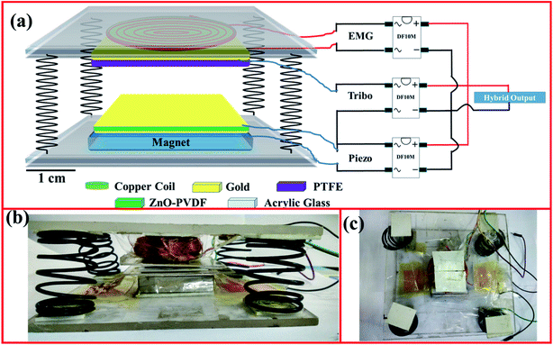
The device we developed was fabricated by stacking triboelectric, piezoelectric, and electromagnetic components. Fig. 1 shows a schematic diagram and photograph of the device. Transparent acrylic glass was used to provide support for the whole set up. A permanent Nd2Fe14B magnet (3 cm × 3 cm × 1 cm) was used and attached to an acrylic sheet with dimensions of 6 cm × 6 cm using double-sided tape. An insulated 3500-turn copper wire (40 SWG) coil with a diameter of 4 cm was attached to another acrylic glass with double-sided tape. For the triboelectric and piezoelectric components, we deployed a ZnO–PVDF nanocomposite film, which is a piezoelectric, flexible freestanding film. Onto both sides of this film, we first deposited a 5 nm-thick layer of Cr and then a gold layer with a thickness of 75 nm. For the counter triboelectric material, we used polytetrafluoroethylene (PTFE), on which a thin layer of Cr (5 nm) and a layer of Au (75 nm) were deposited only on one side of the film. The copper wires were connected through the electrodes using conducting silver paint. After covering the metal electrode with an adhesive insulating tape, the ZnO–PVDF electrode film was attached to the magnet, as shown in Fig. 1(a). The metal-coated side of the PTFE film was similarly attached to the copper coil, which was already fixed to the other acrylic glass. In order to join the two parts, a spring system was used to connect the two acrylic plates. Moreover, the change in the distance between the coil and the magnet during the movement of the magnet in and out of the system led to a change in the magnetic flux and in turn to the electromotive force (emf) induced in the coil. The total height of the device was 6 cm, while the maximum distance between the two contacting triboelectric materials was 2.5 cm.In order to obtain and combine the power outputs of the devices, we constructed the electrical connection as shown in Fig. 1(a). The output from the piezoelectric and triboelectric components was used as an input to low-leakage bridge rectifier ICs (DF10M). The electrical output from the electromagnetic generator was also fed into the input of the bridge rectifier. All of the outputs from the three bridge rectifier ICs were connected in parallel to obtain the hybrid output.
3. Results and discussion
The electrical measurements for the fabricated devices were taken with a Keithley electrometer 6514. We used three low-loss bridge rectifier ICs (DF10M) into which the ac output of each device was fed, as shown in Fig. 1 in the Experimental section. We first measured the rectified voltage and current of each unit. For measuring the rectified output voltage and current of each device, we connected the output terminal of the corresponding bridge rectifier of the device to the input terminal of the electrometer, while the output terminals of the other bridge rectifiers were left open. For example, for measuring the individual output voltage and current of the electromagnetic generator, we connected only the output terminals of the uppermost bridge rectifier IC (A) (as shown in Fig. 1) while the output terminal of the bridge rectifiers of the triboelectric and piezoelectric units (B and C) were left open. However, for measuring the output voltage and current for the hybrid device, we connected the output terminals of all three ICs together, and the common terminal was connected to the input terminal of the electrometer. Fig. 2 shows the measured output voltages and short-circuit currents from the individual units as well as from the hybrid device. As shown in Fig. 2(a), the open-circuit voltage measured from the piezoelectric unit was ∼35 V, while that from the triboelectric unit was ∼140 V and that from the EM generator was ∼4.8 V. The hybrid output gave an open-circuit voltage of ∼192 V.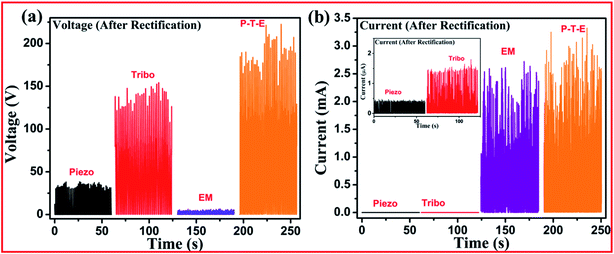 | ||
| Fig. 2 The rectified (a) voltages and (b) currents measured from the individual devices as well as from the hybrid combination. | ||
The measured short-circuit currents from the individual units as well as from the hybrid device are shown in Fig. 2(b). Short-circuit currents of ∼0.4 μA, ∼1.4 μA, and ∼2.29 mA were measured from the piezoelectric unit, triboelectric unit, and electromagnetic (EM) generator, respectively. On combining the three units in parallel, we measured a short-circuit current of ∼2.78 mA from the resulting hybrid device, as shown in Fig. 2(b). In our design, all of the components came into contact simultaneously, and this design led to getting all of the peak voltages and currents simultaneously. The bridge rectifier DF10M, being a low-leakage one, prevented the backflow of the current. In order to calculate the output power from each individual unit, we also measured the voltage drop across different load resistances, as shown in Fig. S1 in ESI.† We calculated the instantaneous output power as V2/R, where V is the voltage drop across the resistor of resistance R. A maximum instantaneous output power of ∼21.2 μW was measured from the piezoelectric unit, and a power of ∼68.1 μW was obtained from the triboelectric unit. However, an instantaneous output power of ∼5.99 mW was obtained from the electromagnetic (EM) generator. Output energy density values were also calculated for the individual units, and found to be 588.9 μW cm−3 for the piezoelectric nanogenerator, 7.57 μW cm−2 for the triboelectric nanogenerator, and 0.476 mW cm−2 for the EM generator. The detailed method followed for the performing these calculations is given in the ESI.† In order to compare the output performance of the present work with that of the previously reported work, a comparison table is given in the ESI.† There has not been much published work about combining piezoelectric, triboelectric, and electromagnetic effects into one device. Most reports have been about hybrid devices that combine just triboelectric and electromagnetic effects; and comparing the results for the individual components, the present device performs better than those previously reported.
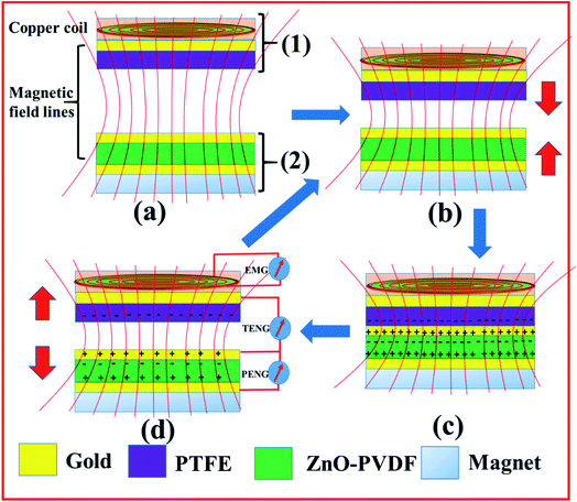
The reason for simultaneously obtaining the outputs from the three devices can be understood from the working principle of the device. The relevant operational diagram is shown in Fig. 3. As can be seen from the schematic diagram (Fig. 3(a)), the device was designed as two parts, with the upper part (part 1) containing a PTFE layer and a copper coil, and the lower part (part 2) containing a ZnO–PVDF film with Au electrodes and a permanent magnet. The present hybrid device was designed with a movable upper part (part 1) and fixed lower part (part 2) so that applying pressure onto the upper part (part 1) would cause it to start approaching the lower part, and removing this pressure would result in its returning to its original position. In this design, when the upper part (part 1) with its attached coil starts approaching the lower part with its attached magnet, the magnetic flux lines passing through the copper coil would start changing, inducing a voltage. Similarly, during the release of the pressure, a negative voltage would be generated due to the change in the magnetic flux across the coil. This process would result in the generation of electricity due to the electromagnetic effect. Note that when the upper part of the device touches the lower part of the device, it would exert pressure on the Au-coated ZnO–PVDF layer of the lower part of the device (part 2) as shown in Fig. 3(c). Due to the piezoelectrical nature of the ZnO–PVDF film, such exertion of pressure would cause a piezo-potential to develop, which in turn would induce charges to develop on the Au electrodes. Thus, electricity would be generated due to the piezoelectric effect of the ZnO–PVDF nanocomposite film. Also, due to the triboelectric effect between PTFE and Au, direct contact of PTFE with the Au-coated ZnO–PVDF layer would result in the generation of charges. And a separation of the parts from one another would induce an electric potential on the electrode deposited on the backside of the PTFE film, leading to generation of electricity (Fig. 3(d)). Pressing the device again would restart this cycle shown in Fig. 3(b)–(d). Such a continuous cycle of contact and separation would generate positive and negative currents that would need to be rectified for driving other electronic devices.
In order to check the charging capability of the devices and to confirm the enhanced performance of the hybrid device, we charged a 10 μF capacitor. As shown in Fig. 4, regarding charging a 10 μF capacitor, the charging was measured to be much faster for the EM generator than for the piezoelectric and triboelectric units—but was even faster for the combined piezo–tribo–EM generator hybrid system. Moreover, the saturation voltage of the capacitor was also higher for the combined piezo–tribo–EM generator. The voltage obtained in a total charging time of 170 s was 7.35 V for the piezo–tribo–EM hybrid generator but only 4.62 V for just the EM generator. A slow increase in the voltage developed across the capacitor when using the triboelectric and piezoelectric nanogenerators, attributed to the very high internal resistance levels of the triboelectric and piezoelectric units, and to dependence of the charging time of the capacitor on the resistance. In contrast, the voltage plateaued quickly in the case of the electromagnetic generator. When we combined all of the units together, the electromagnetic generator quickly charged the capacitor, while the piezoelectric and triboelectric units contributed to the voltage developed across the capacitor continuing to increase. This ability to deploy the hybrid system to achieve more voltage across a capacitor is expected to expand the application of harvested energy to drive devices requiring higher voltage. Our results also demonstrated such hybridization of these three units to be an excellent strategy for achieving enhanced output of power and for expanding the applicability of these devices to drive electronic devices.
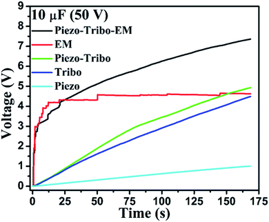 | ||
| Fig. 4 A 10 μF capacitor being charged by the individual units (i.e., piezoelectric, triboelectric, and EM units) as well as by hybrid units. | ||
We have demonstrated several applications of the hybrid system. As shown in Fig. 5(a) and (b), we used the hybrid device to light up several LEDs in series (ESI Video 1†). We also directly powered a digital screw gauge meter (Fig. 5(d)). For a digital scientific calculator, we used a capacitor of 1000 μF, and the power input of the calculator was connected across the capacitor. When the voltage across the capacitor crossed 1.5 V in a short time of ∼7 s, the calculator started working. While using the hybrid system to charge the capacitor, we were able to continuously operate the calculator, and when the hybrid system stopped charging, due to the charge stored in the capacitor, it was able to effectively power the calculator for 25 s (ESI Video 2†).
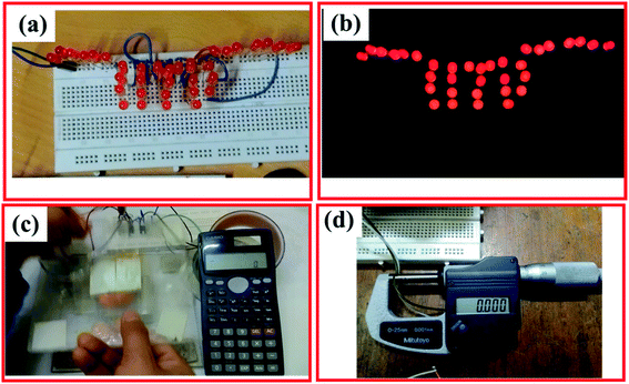 | ||
| Fig. 5 Photographs showing the use of the rectified output power of the piezoelectric–triboelectric–EM generator for (a) and (b) lighting up an LED directly, (c) powering a digital scientific calculator after charging through a 1000 μF capacitor and (d) powering a digital screw gauge meter (see also ESI Videos 1 and 2†). | ||
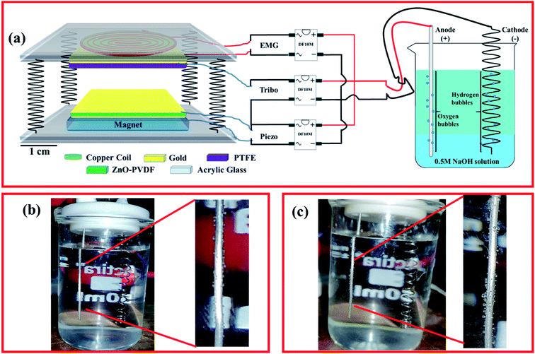
Further, to check the potential of using the hybrid device in applications, we performed electrolysis with the direct power generated from the hybrid device. We connected two platinum (Pt) electrodes to the positive and negative terminals of the combined output, as shown in Fig. 6(a). The two electrodes were dipped into a 0.5 M NaOH solution. The rod-shaped Pt electrode connected to the positive terminal was designed to work as the anode while the spring-shaped Pt electrode connected to the negative terminal was designed to work as the cathode. As we started imparting pressure on the hybrid device for a few seconds, bubbles started forming on both the anode and cathode, attributed to the generation of oxygen (O2) and hydrogen (H2) gases, respectively. In order to compare the performances of the hybrid device and the electromagnetic generator, we checked the number of bubbles generated on the electrode for a fixed time in each case. Over an operation time t of two minutes, more bubbles were observed to be generated in the case of the hybrid device (Fig. 6(c)) than when using the EM generator (Fig. 6(b)), indicative of a better performance of the hybrid device. To verify this conclusion, we measured the current between the two electrodes by connecting a current meter in series. The result also indicated the superiority of the hybrid device over the individual units and established the potential of applying the hybrid device for low powering of devices.
4. Conclusions
We fabricated a piezoelectric–triboelectric–EM generator hybrid mechanical energy harvester. We combined both the piezoelectric and triboelectric effects with a careful selection of the ZnO–PVDF film. We achieved an open-circuit voltage of ∼192 V and a short-circuit current of ∼2.78 mA from the hybrid system after combining the piezoelectric–triboelectric and EM effects. These values were found to be much higher than the output voltages and currents from each effect individually. The design allowed us to obtain simultaneous power outputs from each effect for one mode of vibration. The hybrid system could charge a 10 μF capacitor up to a voltage of 7.35 V in 170 s—while a maximum voltage of only 4.62 V was achieved, and done so rather rapidly, when using just the EM generator. Thus the hybrid device could be applied to power other devices that have higher voltage inputs. The application potential of the hybrid device was shown to include powering several LEDs connected in series, a screw gauge meter, a digital calculator, and the electrolysis of water. This work showed a novel way to generate electricity from mechanical vibrations by combining piezo–triboelectric and EM effects.Conflicts of interest
The authors declare no conflict of interest.Acknowledgements
We acknowledge NRF, IIT Delhi for giving access to the fabrication and characterization facilities, Department of Science and Technology (DST), Ministry of Electronics and Information Technology (MeitY), India are acknowledged for financial support (NNetRA project, RP03530). H. H. S. thanks DST, India, for providing an INSPIRE fellowship (IF150974).References
- Z. L. Wang, ACS Nano, 2013, 7, 9533–9557 CrossRef CAS.
- S. K. Ghosh, T. K. Sinha, B. Mahanty and D. Mandal, Energy Technol., 2015, 3, 1190–1197 CrossRef.
- Y. Hu, J. Yang, S. Niu, W. Wu and Z. L. Wang, ACS Nano, 2014, 8, 7442–7450 CrossRef CAS.
- H. Askari, Z. Saadatnia, E. Asadi, A. Khajepour, M. B. Khamesee and J. Zu, Nano Energy, 2018, 45, 319–329 CrossRef CAS.
- D. Ponnamma and M. A. A. Al-Maadeed, Sustainable Energy Fuels, 2019, 3, 774–785 RSC.
- S. Tiwari, A. Gaur, C. Kumar and P. Maiti, Sustainable Energy Fuels, 2020, 4, 2469–2479 RSC.
- S. P. Machado, M. Febbo, F. Rubio-Marcos, L. A. Ramajo and M. S. Castro, Smart Mater. Struct., 2015, 24, 115011 CrossRef.
- S. Bairagi and S. W. Ali, Int. J. Energy Res., 2020, 1–19 Search PubMed.
- P. Thakur, A. Kool, N. A. Hoque, B. Bagchi, F. Khatun, P. Biswas, D. Brahma, S. Roy, S. Banerjee and S. Das, Nano Energy, 2018, 44, 456–467 CrossRef CAS.
- N. A. Hoque, P. Thakur, S. Roy, A. Kool, B. Bagchi, P. Biswas, M. M. Saikh, F. Khatun, S. Das and P. P. Ray, ACS Appl. Mater. Interfaces, 2017, 9, 23048–23059 CrossRef CAS.
- S. K. Singh, S. Muduli, D. Dhakras, R. Pandey, R. Babar, A. Singh, D. Kabra, M. Kabir, R. Boomishankar and S. Ogale, Sustainable Energy Fuels, 2019, 3, 1943–1950 RSC.
- H. Chen, C. Xing, Y. Li, J. Wang and Y. Xu, Sustainable Energy Fuels, 2020, 4, 1063–1077 RSC.
- R. I. Haque and D. Briand, Smart Mater. Struct., 2019, 28, 085002 CrossRef CAS.
- D. Hong, Y. M. Choi, Y. Jang and J. Jeong, Int. J. Energy Res., 2018, 42, 3688–3695 CrossRef CAS.
- K. Parida, V. Kumar, W. Jiangxin, V. Bhavanasi, R. Bendi and P. S. Lee, Adv. Mater., 2017, 1702181 CrossRef.
- X. Cui, S. Cao, Z. Yuan, G. Xie, J. Ding, S. Sang and H. Zhang, Energy Technol., 2019, 7(5), 1800931 CrossRef.
- Y. Yang, H. Zhang, J. Chen, Q. Jing, Y. S. Zhou, X. Wen and Z. L. Wang, ACS Nano, 2013, 7, 7342–7351 CrossRef CAS.
- G. Zhu, C. Pan, W. Guo, C. Y. Chen, Y. Zhou, R. Yu and Z. L. Wang, Nano Lett., 2012, 12, 4960–4965 CrossRef CAS.
- S. Y. Yang, J. F. Shih, C. C. Chang and C. R. Yang, Appl. Phys. A: Mater. Sci. Process., 2017, 123, 1–10 Search PubMed.
- J. Liu, A. Goswami, K. Jiang, F. Khan, S. Kim, R. McGee, Z. Li, Z. Hu, J. Lee and T. Thundat, Nat. Nanotechnol., 2018, 13, 112–116 CrossRef CAS.
- G. Suo, Y. Yu, Z. Zhang, S. Wang, P. Zhao, J. Li and X. Wang, ACS Appl. Mater. Interfaces, 2016, 8, 34335–34341 CrossRef CAS.
- A. Li, Y. Zi, H. Guo, Z. L. Wang and F. M. Fernández, Nat. Nanotechnol., 2017, 12, 481–487 CrossRef CAS.
- S. Bairagi and S. W. Ali, Org. Electron., 2019, 78, 105547 CrossRef.
- H. H. Singh, S. Singh and N. Khare, Polym. Adv. Technol., 2018, 29, 143–150 CrossRef CAS.
- S. K. Ghosh and D. Mandal, Appl. Phys. Lett., 2016, 109, 103701 CrossRef.
- H. Askari, E. Asadi, Z. Saadatnia, A. Khajepour, M. B. Khamesee and J. Zu, Nano Energy, 2017, 32, 105–116 CrossRef CAS.
- W. Wang, J. Xu, H. Zheng, F. Chen, K. Jenkins, Y. Wu, H. Wang, W. Zhang and R. Yang, Nanoscale, 2018, 10, 14747–14754 RSC.
- Z. Li, Z. Saadatnia, Z. Yang and H. Naguib, Energy Convers. Manage., 2018, 174, 188–197 CrossRef.
- R. Ahmed, Y. Kim, M. U. Mehmood, Zeeshan, U. Shaislamov and W. Chun, Int. J. Energy Res., 2019, 43, 5852–5863 CrossRef.
- X. Chen, L. Gao, J. Chen, S. Lu, H. Zhou, T. Wang, A. Wang, Z. Zhang, S. Guo, X. Mu, Z. L. Wang and Y. Yang, Nano Energy, 2020, 69, 104440 CrossRef CAS.
- Y. Purusothaman, G. Khandelwal and R. Pandey, Nano Energy, 2019, 64, 103926 CrossRef.
- L. Liu, W. Tang, C. Deng, B. Chen, K. Han, W. Zhong and Z. L. Wang, Nano Res., 2018, 11, 3972–3978 CrossRef CAS.
- B. Zhang, J. Chen, L. Jin, W. Deng, L. Zhang, H. Zhang, M. Zhu, W. Yang and Z. L. Wang, ACS Nano, 2016, 10, 6241–6247 CrossRef CAS.
- K. Zhang, X. Wang, Y. Yang and Z. L. Wang, ACS Nano, 2015, 9, 3521–3529 CrossRef CAS.
Footnote |
| † Electronic supplementary information (ESI) available. See DOI: 10.1039/d0se01201g |
| This journal is © The Royal Society of Chemistry 2021 |

