Thermoelectric all-carbon heterostructures for a flexible thermoelectric generator†
Hyeonseok
Hwang
and
Kwang-Suk
Jang
 *
*
Department of Applied Chemistry (Major in Bionano Convergence), Hanyang University, Ansan, Gyeonggi-do 15588, Republic of Korea. E-mail: kjang@hanyang.ac.kr
First published on 11th November 2020
Abstract
Carbon nanotubes (CNTs) are thermoelectric materials with immense potential because of their flexible, lightweight, and solution-processable properties. Herein, we report a facile method for improving the thermoelectric performance of CNTs for application in flexible thermoelectric generators. By introducing carbon nanoparticles (CNPs) between the CNTs, all-carbon heterostructures could be formed. A barrier energy at the CNT–CNP interface can directly enhance the Seebeck coefficient (S). The all-carbon heterostructure films exhibited S and power factor values as high 54.0 ± 1.4 μV K−1 and 503 ± 49 μW m−1 K−2, respectively, which are 1.9 and 2.3 times higher than those of the CNT films without the heterostructures. Note that the thermoelectric performance is considered only from the point of view of the power factor. For complete characterization, the evaluation of thermal conductivity would be required. Using the all-carbon heterostructures as thermoelectric elements, a flexible thermoelectric generator of three-dimensionally stacked elements was fabricated for efficiently harvesting energy from a vertical temperature difference. The thermoelectric generator with a thermal contact area of 6 cm2 exhibited a maximum output power of 4.8 μW from a vertical temperature difference of 30 K. Thus, we developed a facile strategy for synthesizing high-performance thermoelectric all-carbon heterostructures and demonstrated their superior ability to harvest thermoelectric energy.
Introduction
Thermoelectric materials have been extensively studied for applications in thermoelectric generators, which convert waste heat into electricity, and Peltier coolers. The performance of thermoelectric materials is evaluated by the dimensionless figure of merit ZT = S2σT/κ, where S, σ, T, and κ denote the Seebeck coefficient, electrical conductivity, absolute temperature, and thermal conductivity, respectively. The power factor PF = S2σ can be occasionally used as an alternative to ZT due to the difficulty of measuring thermal conductivities. Recently, organic thermoelectric materials have attracted great interest because of their potential application in flexible and wearable thermoelectric generators. Conjugated polymers such as poly(3,4-ethylenedioxythiophene) (PEDOT) have been widely studied as organic thermoelectric materials because they are flexible, lightweight, and solution-processable.1–6 Bubnova et al. reported that PEDOT:tosylate thin films exhibited a PF up to 324 μW m−1 K−2.1 Kim et al. reported that PEDOT:poly(styrenesulfonate) thin films exhibited a PF up to 469 μW m−1 K−2.2,3 Until now, the physical form of most conjugated polymers has been limited to a thin film. It was reported that the thickness of organic thermoelectric films strongly affects the doping behavior, thermoelectric properties, and stability.7 Fabrication of high-performance and thick organic thermoelectric films might be challenging. For practical applications, diverse physical forms of thermoelectric conjugated polymers need to be developed to reduce the internal resistance and achieve diverse geometries of thermoelectric devices. Recently, thick thermoelectric films with a thickness over 1 μm have been used to fabricate effective thermoelectric generators.7,8In addition to conjugated polymers, single-walled carbon nanotubes (CNTs), which are flexible, lightweight, and solution-processable, are also emerging thermoelectric materials.9–16 Avery et al. reported that separated semiconducting CNT films exhibited a PF up to 340 μW m−1 K−2.9 Thermoelectric CNTs with various physical forms, such as freestanding films, fibers, and shape-deformable dough, have been reported.12–16 Because of their unique one-dimensional shape and flexibility, CNTs form numerous junctions between their bundles. The networks of well de-bundled CNTs exhibit excellent σ values. The as-grown single-walled CNTs are a mixture of semiconductors and metals because the nanotube geometry such as the diameter and rolling direction, which affect the electrical properties of individual CNTs, could not be finely controlled till now.9 Thus, S of CNTs is restricted by the existence of metallic CNTs with an S near zero. If the S value of CNTs can be increased without severe loss in σ by the energy filtering effect, CNTs can be a promising thermoelectric material. By forming heterostructures with an optimal barrier energy in thermoelectric materials, the energy filtering effect can be introduced.17–22 The barrier energy at the interface of heterostructures restricts the transport of low-energy carriers but does not affect the transport of high-energy carriers. Thus, a larger density gradient of carriers could be generated, resulting in a higher S without severe loss in σ.
Herein, we report a facile method for enhancing the thermoelectric PFs of CNTs by using the energy filtering effect. By introducing carbon nanoparticles (CNPs) between the CNT bundles, CNT–CNP–CNT junctions with a barrier energy were generated. CNPs are chosen as a barrier material for the energy filtering effect, because CNPs can form intimate contact on the CNT surface, their diameter is comparable to the mean free path of carriers, and their barrier energy can restrict the transport of low energy carriers effectively. To form the CNT–CNP heterostructures, CNT–polymer composite films were burned using a commercial gas lighter. The polymer chains were combusted, leaving CNPs between the CNTs. The combusted all-carbon heterostructure films exhibited S and PF values as high as 54.0 ± 1.4 μV K−1 and 503 ± 49 μW m−1 K−2, respectively, which are 2.8 and 5.5 times higher than those of the as-prepared CNT films. Using the all-carbon heterostructures as thermoelectric elements, a flexible thermoelectric generator of three-dimensionally (3D) stacked elements was fabricated for efficiently harvesting energy from a vertical temperature difference (ΔT). A thermoelectric generator with a thermal contact area of 6 cm2 exhibited a maximum output power of 4.8 μW from a ΔT of 30 K.
Results and discussion
To prepare CNT–polymer composite films, poly(ethylene-alt-maleic anhydride) (PEMA) was used as a polymer additive. According to molecular dynamics simulations, individual PEMA chains prefer to be located between CNTs in the dispersion solvent.23 Freestanding CNT-PEMA films with CNT contents of 50 to 90 wt% were prepared by a bar-coating process. The thickness of the CNT–PEMA films was ∼20 μm. We tried to maximize the thickness of the composite films in order to reduce the internal resistance of the final device. The thickness of the composite films can be controlled by the solid concentration of the pastes and the gap size for bar-coating. When using the pastes with a solid concentration over 1 wt% or a gap size over 1 mm which will be the thickness of wet films, homogeneous surface morphologies of the composite films could not be obtained due to crack and void formation while drying. To form the all-carbon heterostructures, the CNT–PEMA films were combusted, leaving CNPs between the CNTs. Fig. 1a–e show the scanning electron microscopy (SEM) images of the as-prepared and combusted CNT–PEMA films with CNT contents of 50 to 90 wt%. In all films, the networks of CNT bundles, which are the electrical pathways, are clearly visible. After the combustion process, spherical nanoparticles, i.e., CNPs, were formed on the CNT bundles, forming the CNT–CNP heterostructure. The diameter of the CNPs is in the range of 10–80 nm. For comparison, the as-prepared and combusted CNT films, denoted as films with a CNT content of 100 wt%, were also prepared (Fig. 1f). Note that there should be impurities in the CNT films because the purity of the purchased CNT product is ≥80%. In the combusted CNT film, CNPs on CNT bundles are also observed. After the combustion, the water contact angle of the CNT films decreased from 116° to 66°, which might be due to CNP formation by the combustion of the CNT–PEMA films, the PEMA, solvent residue, and/or impurities in the purchased CNT product. To confirm the complete removal of the polymer, thermogravimetric analysis (TGA) of the as-prepared and combusted CNT–PEMA films with CNT contents of 50 to 100 wt% was performed in air (Fig. S1†). The PEMA in all CNT–polymer films was decomposed in the temperature range of 200–400 °C, while the thermal decomposition of CNTs was observed mainly at temperatures >500 °C. Because weight loss at temperatures <500 °C was not observed in all combusted CNT–PEMA films, it can be concluded that the polymer chains do not exist after the combustion process.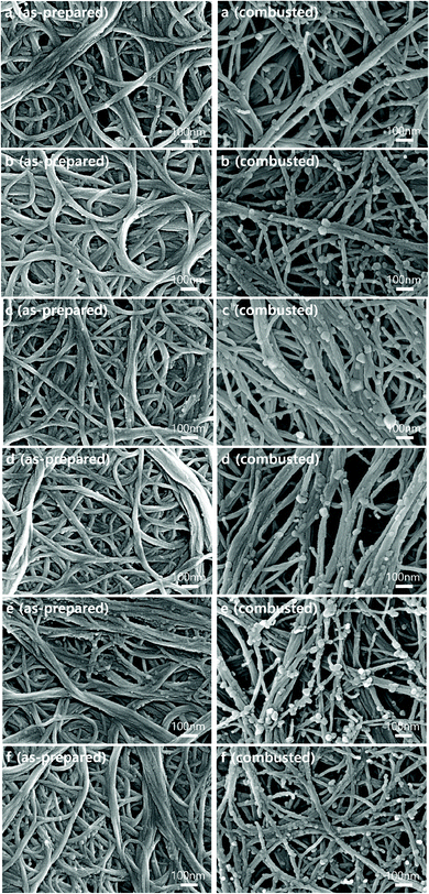 | ||
| Fig. 1 SEM images of the as-prepared and combusted CNT–PEMA films with CNT contents of (a) 50, (b) 60, (c) 70, (d) 80, (e) 90, and (f) 100 wt%. | ||
The combustion of the polymer chains can also be discussed in terms of the pore volume and surface area of the films. Fig. S2† shows nitrogen adsorption/desorption isotherms of the as-prepared and combusted CNT–PEMA films with CNT contents of 50 to 100 wt%. All films exhibit type-IV isotherms with a hysteresis loop. Using the Barrett–Joyner–Halenda (BJH) method and Brunauer–Emmett–Teller (BET) method, the pore volumes and surface areas of the films were determined, respectively (Fig. 2a and b). After the combustion process, the pore volume and surface area of the CNT film are increased slightly. This might be due to the evaporation of the solvent residue and/or sublimation of impurities in the purchased CNT product. On the other hand, the combustion process significantly increased the pore volume and surface area of the CNT–PEMA films with CNT contents of 50 to 90 wt% due to the complete removal of the PEMA polymer chains while leaving the CNPs intact. Fig. S3† shows the Raman spectra of the as-prepared and combusted CNT–PEMA films with CNT contents of 50 to 100 wt%. The strong Raman peaks at 1580 cm−1 and 1350 cm−1 correspond to the G band of the sp2 graphitic vibration and the D band of the sp3 defect, respectively. The ratio of the intensities of the D-band to the G-band (ID/IG) indicates the formation of defect sites in the CNTs. All the films exhibited very low ID/IG ratios in the range of 0.025–0.041. Because the change in ID/IG was negligible, it can be concluded that the CNTs were not damaged during the combustion.
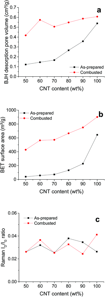 | ||
| Fig. 2 (a) BJH desorption pore volumes, (b) BET surface areas, and (c) ID/IG intensity ratios of the as-prepared and combusted CNT–PEMA films with respect to the CNT content. | ||
By introducing CNPs between the CNTs, the CNT–CNP–CNT junctions with a barrier energy could be generated (Fig. 3). The barrier energy (ΔE) between CNPs and CNTs is estimated using ΔE = ΦCNP − ΦCNT, where ΦCNP and ΦCNT denote the work functions of CNPs and CNTs, respectively. To extract the work function of CNPs, PEMA was combusted and pelletized. The work functions of the combusted PEMA and CNTs were measured to be 5.50 and 5.22 eV using a photoelectron spectrometer (Fig. S4†). Thus, the barrier energy between the CNPs, carbonized from PEMA, and CNTs is estimated to be ∼0.3 eV. The barrier energy at the interface of the heterostructures can result in an enhancement of S.18–22 The energy barrier restricts the transport of low energy carriers but does not affect the transport of high energy carriers. Although the total carrier transport decreases with a decrease in σ, a larger density gradient of carriers could be generated with an increase in S by the energy filtering of carriers. It was experimentally confirmed that a barrier energy of 0.1–0.3 eV is optimal for efficient energy filtering of carriers.11,19,20Fig. 4 shows the S, σ, and PF values of the as-prepared and combusted CNT–PEMA films with CNT contents of 50 to 100 wt%. Because CNTs have p-type characteristics in air, all the films exhibited positive S values. The S values of the CNT films and CNT–PEMA films with a CNT content of 90 wt% were not affected by the combustion process. The PEMA chains located between CNTs prevent bundling of CNTs in the dispersion solvent.23 During solvent drying, well-dispersed CNT bundles could form Y-shaped bundle junctions with each other (Fig. 1). The junctions formed by π–π interactions of bare CNTs would be the electrical pathways. The CNT–PEMA films exhibit excellent electrical conductivities. In the CNT–PEMA films with CNT contents of 50 to 80 wt%, the energy filtering effect, i.e., an increase in S and a decrease in σ, is induced by the combustion process. The increase in S and decrease in σ can be attributed to the energy filtering effect at the heterostructure interfaces with CNP barriers. The restricted transport of low energy carriers at the heterostructure interfaces can result in the increase of S and decrease of σ. The PEMA content strongly affects the S values of the combusted CNT–PEMA films. At a PEMA content of 30 wt%, i.e., a CNT content of 70 wt%, the combusted CNT–PEMA films exhibit a maximum S value of 54.0 ± 1.4 μV K−1, which is 2.8 times higher than that of the as-prepared CNT films. As a result, the combusted CNT–PEMA films with a CNT content of 70 wt% exhibit a maximum PF value of 503 ± 49 μW m−1 K−2, which is 5.5 times higher than that of the as-prepared CNT films. The energy filtering effect can be optimized at a specific barrier energy.11,19,20 The CNPs, barriers between CNTs, were formed by the combustion of entire polymer chains. At a CNT content of 70 wt%, a barrier energy suitable for energy filtering at the heterostructure might be generated by the combustion process. Fig. S5† shows the cross-sectional SEM image of the combusted CNT–PEMA film with a CNT content of 70 wt%. Well-dispersed CNT bundles, their Y-shaped bundle junctions, and well-distributed CNPs are clearly visible.
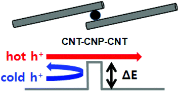 | ||
| Fig. 3 Schematic illustration of the energy filtering of carriers in the CNT–CNP–CNT heterostructure. | ||
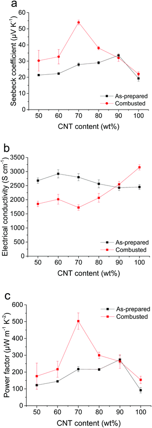 | ||
| Fig. 4 (a) S, (b) σ, and (c) PF values of the as-prepared and combusted CNT–PEMA films with respect to the CNT content. | ||
To build thermoelectric generators, both p- and n-type thermoelectric materials are needed. For n-type doping, combusted CNT–PEMA films with a CNT content of 70 wt% (CNT–CNP films) were immersed in PEI/ethanol solutions with concentrations of 0.5–3 wt%. The amine-rich PEI molecules attached to the CNT surfaces donate electrons to the CNTs for n-type doping.24–26Fig. 5 shows the S, σ, and PF values of the PEI-treated CNT–CNP films as a function of the PEI concentration. The PEI-treated CNT–CNP films exhibited n-type characteristics. The PEI-treated CNT–CNP films exhibited the highest PF of 340 ± 10 μW m−1 K−2 at a PEI concentration of 1.5 wt%. For comparison, non-combusted and PEI-treated CNT–PEMA films with a CNT content of 70 wt% were also prepared. However, they exhibited p-type characteristics. The S, σ, and PF values of the non-combusted and 1.5 wt% PEI-treated CNT–PEMA films with a CNT content of 70 wt% were 37 ± 3 μV K−1, 1000 ± 8 S cm−1, and 150 ± 24 μW m−1 K−2, respectively. For n-type doping, the PEI molecules should be adsorbed on the bare surface of CNTs. However, the PEMA polymer chains located between the CNT bundles could hinder the attachment of the PEI to the CNT surfaces. The 1.5 wt% PEI-treated CNT–CNP films were aged in the ambient environment with a relative humidity of approximately 50% to investigate the air stability of their thermoelectric properties (Fig. S6†). In the PEI-treated CNT–CNP films, the S and σ values decrease with aging. After 2 days, there is a 17% decrease in S and 13% decrease in σ. The stability in air might be improved by the passivation treatment, which is our ongoing study.
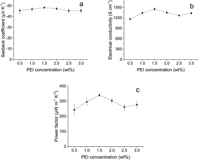 | ||
| Fig. 5 (a) S, (b) σ, and (c) PF values of the combusted and PEI-treated CNT–PEMA films with a CNT content of 70 wt% as a function of the PEI concentration. | ||
The CNT–CNP films could be folded or electrically connected using the CNT/chloroform paste as a conductive adhesive without an increase in the resistance (Fig. S7†). Using the neat and PEI-doped CNT–CNP films as p- and n-type thermoelectric elements, respectively, a flexible thermoelectric generator of 3D stacked elements was built for the efficient harvesting of energy from a vertical ΔT (Fig. 6a). The electrode film, prepared by bar-coating with the CNT/chloroform paste, was electrically connected to the thermoelectric elements using the CNT/chloroform paste as a conductive adhesive. To fabricate the 3D stacked thermoelectric generator, 120 thermoelectric elements with a length of 2 cm and a width of 0.5 cm were assembled by stacking 30 sheets of the individual paper-based devices. To demonstrate the energy-harvesting capacity of the thermoelectric generator, a vertical ΔT was applied using Peltier plates. The ΔT between the top and bottom Peltier plates were set to 10, 20, and 30 K. Fig. 6b shows the output voltage vs. output current and output power vs. output current curves for the 3D stacked thermoelectric generator with a thermal contact area of 6 cm2. Maximum output powers of 0.59, 2.3, and 4.8 μW were generated from a vertical ΔT of 10, 20, and 30 K, respectively. The measured maximum output power is roughly proportional to the square of the vertical ΔT, because the generated voltage is proportional to the applied ΔT. A 3D stacked thermoelectric generator for the effective harvesting of energy from a vertical ΔT was successfully demonstrated. The device performance can be enhanced by optimizing the dimensions of thermoelectric elements and reducing the contact resistance between thermoelectric elements and electrodes. The energy filtering effect at the CNP barrier between the CNTs can substantially enhance the thermoelectric performance. Because the CNT-based thermoelectric materials are flexible and can have diverse physical forms, thermoelectric devices of various geometries can be fabricated using the assembling and stacking strategies. CNT–CNP films with a length of 3 cm and a width of 0.6 cm were fabricated by a simple combustion process. In the cross-sectional SEM image of the combusted CNT–PEMA film with a CNT content of 70 wt%, CNPs are uniformly distributed (Fig. S5†). All the thermoelectric properties averaged from ten different samples have narrow distributions (Fig. 4). However, for large-scale production, controlling the uniformity of the films will be challenging.
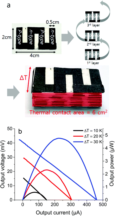 | ||
| Fig. 6 (a) Schematic and photographs showing the fabrication process and (b) output voltage vs. output current and output power vs. output current curves of the 3D stacked thermoelectric generator. | ||
Conclusions
In summary, the energy filtering effect of the all-carbon heterostructures for enhancing the thermoelectric PFs was investigated. The CNT–CNP heterostructures were fabricated by the combustion of the CNT–PEMA composite films. A barrier energy at the CNT–CNP interface can result in an enhancement of S, because the energy barrier restricts transport of low energy carriers, but does not affect the transport of high energy carriers. The CNT–CNP films exhibited a p-type PF up to 503 ± 49 μW m−1 K−2 at room temperature. Using the neat and PEI-doped CNT–CNP films as p- and n-type thermoelectric elements, respectively, a flexible thermoelectric generator of 3D stacked elements was fabricated for the effective harvesting of energy from a vertical ΔT. The thermoelectric generator exhibited a maximum output power of 4.8 μW with a vertical ΔT of 30 K. The demonstrated strategy of enhancing the PF by introducing CNP barriers can be a promising route to achieving high-performance flexible thermoelectric materials and efficient flexible thermoelectric devices.Experimental section
Preparation of thermoelectric films
Single-walled CNTs (Tuball, purity ≥80%) were obtained from OCSiAl. The CNTs have diameters of 0.5–2 nm with a mean value of 1.6 nm and lengths of 1–10 μm. PEMA (MW = 100![[thin space (1/6-em)]](https://www.rsc.org/images/entities/char_2009.gif) 000–500
000–500![[thin space (1/6-em)]](https://www.rsc.org/images/entities/char_2009.gif) 000), dimethyl sulfoxide (DMSO, purity >99.7%), branched PEI (MW = 600), ethanol (purity >99.8%), and chloroform (purity >99.5%) were purchased from Sigma–Aldrich. All the chemicals were used as received. For the preparation of the paste, CNTs, PEMA, and DMSO were mixed using a ball mill (Retsch MM400) at 30 Hz for 60 min. The solid concentration of the pastes was fixed at 1 wt%. The CNT–polymer films were fabricated via simple bar-coating of the pastes on a glass substrate. The bar-coated films were dried at 150 °C for 3 h and peeled off. To obtain CNT–CNP films, CNT–polymer films with a length of 3 cm and a width of 0.6 cm were burned using a commercial gas lighter for 5 s. For the n-type doping of CNTs, the freestanding films were immersed in PEI/ethanol solutions for 5 min, rinsed with ethanol, and dried.
000), dimethyl sulfoxide (DMSO, purity >99.7%), branched PEI (MW = 600), ethanol (purity >99.8%), and chloroform (purity >99.5%) were purchased from Sigma–Aldrich. All the chemicals were used as received. For the preparation of the paste, CNTs, PEMA, and DMSO were mixed using a ball mill (Retsch MM400) at 30 Hz for 60 min. The solid concentration of the pastes was fixed at 1 wt%. The CNT–polymer films were fabricated via simple bar-coating of the pastes on a glass substrate. The bar-coated films were dried at 150 °C for 3 h and peeled off. To obtain CNT–CNP films, CNT–polymer films with a length of 3 cm and a width of 0.6 cm were burned using a commercial gas lighter for 5 s. For the n-type doping of CNTs, the freestanding films were immersed in PEI/ethanol solutions for 5 min, rinsed with ethanol, and dried.
Preparation of the thermoelectric generator
The CNT–CNP and PEI-doped CNT–CNP films were used as p- and n-type thermoelectric elements, respectively. The electrode film was prepared by bar-coating with a 1 wt% CNT/chloroform paste. On a paper substrate with a length of 2 cm and a width of 4 cm, two pairs of p- and n-type elements with a length of 2 cm and a width of 0.5 cm were attached. The alternating p- and n-type elements were electrically connected with the electrode film using the CNT/chloroform paste as a conductive adhesive. The 30 paper-based devices were 3D stacked using the folded electrodes as the electrical connection of each layer.Characterization
The surface morphologies of the thermoelectric films were observed using field-emission SEM (Hitachi S4800, operated at 15 kV). The values of S were determined under ambient conditions using a custom-built measurement system. S-Type thermocouples for the measurement of ΔT and gold probe tips for the measurement of the generated voltage (ΔV) were directly in contact with the thermoelectric films. The values of ΔV were determined using a Keithley 2182A nanovoltmeter. The temperatures of the cold and hot sides of the thermoelectric films were controlled using two Peltier plates, where the Peltier current is controlled via a feedback loop using a Keithley 2700 multimeter and Keithley 2604B source meter. The value of ΔT was varied from 1 to 8 K. At each ΔT point, ΔV was measured 20 times, and the average ΔV value was obtained. The value of S was obtained from the slope of the ΔV–ΔT curve (Fig. S8†).12–16 The surface resistances of the thermoelectric films were measured using the standard four-point probe method with an FPP-RS8 instrument (Dasoleng). The work function was measured using a surface analyzer photoelectron spectrometer (AC-2, Riken). The nitrogen adsorption/desorption isotherms were obtained using a surface analyzer (3Flex, Micromeritics). Raman spectra were obtained using a Raman spectrometer (Jasco NRS-3100). The electrical power generation capability of the thermoelectric generator was evaluated using a custom-built measurement system. The vertical ΔT was applied to the thermoelectric generator using Peltier plates, which were controlled delicately using a Keithley 2700 multimeter and a Keithley 2604B source meter. The output voltage vs. output current and output power vs. output current curves were measured by varying the load resistance.Conflicts of interest
There are no conflicts to declare.Acknowledgements
This research was supported by the Basic Research Program through the National Research Foundation of Korea (NRF) funded by the MSIT (2020R1A4A4079870) and by the research fund of Hanyang University (HY-2020-2476).References
- O. Bubnova, Z. U. Khan, A. Malti, S. Braun, M. Fahlman, M. Berggren and X. Crispin, Nat. Mater., 2011, 10, 429–433 CrossRef CAS.
- G.-H. Kim, L. Shao, K. Zhang and K. P. Pipe, Nat. Mater., 2013, 12, 719–723 CrossRef CAS.
- M. Chabinyc, Nat. Mater., 2013, 13, 119–121 CrossRef.
- R. Kroon, D. A. Mengistie, D. Kiefer, J. Hynynen, J. D. Ryan, L. Yu and C. Müller, Chem. Soc. Rev., 2016, 45, 6147–6164 RSC.
- H. Wang, L. Yin, X. Pu and C. Yu, Polymer, 2013, 54, 1136–1140 CrossRef CAS.
- X. Crispin, S. Marciniak, W. Osikowicz, G. Zotti, A. W. D. van der Gon, F. Louwet, M. Fahlman, L. Groenendaal, F. De Schryver and W. R. Salaneck, J. Polym. Sci., Part B: Polym. Phys., 2003, 41, 2561–2583 CrossRef CAS.
- S. Hwang, W. J. Potscavage Jr, R. Nakamichi and C. Adachi, Org. Electron., 2016, 31, 31–40 CrossRef CAS.
- S. Mardi, M. R. Abbrogioni and A. Reale, Mater. Res. Express, 2020, 7, 085101 CrossRef CAS.
- A. D. Avery, B. H. Zhou, J. Lee, E.-S. Lee, E. M. Miller, R. Ihly, D. Wesenberg, K. S. Mistry, S. L. Guillot, B. L. Zink, Y.-H. Kim, J. L. Blackburn and A. J. Ferguson, Nat. Energy, 2016, 1, 16033 CrossRef CAS.
- M.-H. Lee, Y. H. Kang, J. Kim, Y. K. Lee and S. Y. Cho, Adv. Energy Mater., 2019, 9, 1900914 CrossRef.
- J.-H. Hsu and C. Yu, Nano Energy, 2020, 67, 104282 CrossRef CAS.
- J.-Y. Kim, W. Lee, Y. H. Kang, S. Y. Cho and K.-S. Jang, Carbon, 2018, 133, 293–299 CrossRef CAS.
- J.-Y. Kim, J.-H. Mo, Y. H. Kang, S. Y. Cho and K.-S. Jang, Nanoscale, 2018, 10, 19766–19773 RSC.
- J.-H. Mo, J.-Y. Kim, Y. H. Kang, S. Y. Cho and K.-S. Jang, ACS Sustainable Chem. Eng., 2018, 6, 15970–15975 CrossRef CAS.
- S. Kim, J.-H. Mo and K.-S. Jang, ACS Appl. Mater. Interfaces, 2019, 11, 35675–35682 CrossRef CAS.
- S. Park, J.-H. Mo, S. Kim, H. Hwang and K.-S. Jang, ACS Appl. Mater. Interfaces, 2020, 12, 19415–19422 CrossRef CAS.
- N. Neophytou and H. Kosina, J. Appl. Phys., 2013, 114, 044315 CrossRef.
- C. Gayner and Y. Amouyal, Adv. Funct. Mater., 2019, 30, 1901789 CrossRef.
- J. Choi, J. Y. Lee, S.-S. Lee, C. R. Park and H. Kim, Adv. Energy Mater., 2016, 6, 1502181 CrossRef.
- W. S. Kim, G. Anoop, I.-S. Jeong, H. J. Lee, H. B. Kim, S. H. Kim, G. W. Goo, H. Lee, H. J. Lee, C. Kim, J.-H. Lee, B. S. Mun, J.-W. Park, E. Lee and J. Y. Jo, Nano Energy, 2020, 67, 104207 CrossRef CAS.
- M. He, J. Ge, Z. Lin, X. Feng, X. Wang, H. Lu, Y. Yang and F. Qiu, Energy Environ. Sci., 2012, 5, 8351–8358 RSC.
- D.-K. Ko, Y. Kang and C. B. Murray, Nano Lett., 2011, 11, 2841–2844 CrossRef CAS.
- J.-H. Mo, K. C. Kim and K.-S. Jang, J. Ind. Eng. Chem., 2019, 80, 190–196 CrossRef CAS.
- M. Shim, A. Javey, N. W. S. Kam and H. J. Dai, J. Am. Chem. Soc., 2001, 123, 11512–11513 CrossRef CAS.
- C. Yu, A. Murali, K. Choi and Y. Ryu, Energy Environ. Sci., 2012, 5, 9481–9486 RSC.
- Y. Ryu, D. Freeman and C. Yu, Carbon, 2011, 49, 4745–4751 CrossRef CAS.
Footnote |
| † Electronic supplementary information (ESI) available. See DOI: 10.1039/d0se01591a |
| This journal is © The Royal Society of Chemistry 2021 |
