 Open Access Article
Programmed topographical features generated on command in confined electroactive films†
Fabian L. L.
Visschers
ab,
Dirk J.
Broer
 abc and
Danqing
Liu
 *abc
*abc
aDepartment of Chemical Engineering & Chemistry, Eindhoven University of Technology, De Rondom, Eindhoven 5612 AP, The Netherlands. E-mail: d.liu1@tue.nl
bInstitute for Complex Molecular Systems (ICMS), Eindhoven University of Technology, De Rondom 70, Eindhoven 5612 AP, The Netherlands
cSCNU-TUE Joint Lab of Device Integrated Responsive Materials (DIRM), South China Normal University, Guangzhou Higher Education Mega Center, P. R. China
First published on 28th June 2021
Abstract
This work describes a method to create dynamic pre-programmed surface textures by an alternating electric field on coatings that consist of a silicon oxide reinforced viscoelastic siloxane network. The finite element method is developed to predict the complex deformation figures and time-resolved experimental topographical surface analysis is used to confirm them.
1. Introduction
In many physical objects, the texture of surfaces plays a crucial role as it affects friction,1 (cell) adhesion,2,3 heat transfer,4 lubrication,5 corrosion,6 wear7 and reflective properties.8 Furthermore, the visual texture of a surface can be used in product design to trigger specific emotions and feelings. The neuropsychological and neuroaesthetic models behind the aesthetic perception of visual textures have been extensively researched.9–17 Additionally, the quantitative characterization of surface textures has been reviewed in multiple books18,19 and research papers,20,21 which further endorses its importance. Moving forward, scientists are now exploring methods to provide active control over surface textures by creating dynamic surface micro-structures. Control over these dynamic surfaces provides a major advantage as it grants inherent control over the many functionalities associated with surface textures. Moreover, dynamic surface textures can provide new aspects to aesthetic perceptions and lead to interesting new applications like active mixing in microfluidics or unidirectional transport of matter over a surface. In the literature, many examples already exist of coatings that alter their surface structure in response to a variety of external stimuli like pH,22 light,23,24 temperature25,26 and electricity.27–30 We argue that for electronics-related applications, active control is provided best by using electricity as a stimulus, as it complies with already integrated driving schemes as for instance used in touch-pads for computers and operating systems. In this context, we now present a method to create dynamic pre-programmed surface textures31–33 by using a continuously alternating electric field on coatings that consist of a silicon oxide reinforced viscoelastic siloxane network. The results are based on our previous work where we introduce a new method to generate oscillating waves under a continuous AC electric field.34,35 In this publication, we apply a similar coating but modify the electrode structures to add desired complexity to the deformation patterns. Based on our models we are able to predict the complex deformation figures and confirm them by time-resolved experimental topographical surface analysis. Lastly, we also provide demonstrations of the optical effects that result from the change in texture of our coatings.2. Results and discussion
2.1. Design principle
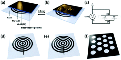
In our approach towards complex surface deformation patterns, we have chosen a rigid glass substrate provided with lithographically etched indium tin oxide (ITO) electrode patterns. The spin-coated electro-active polymer consists of a loosely crosslinked poly(dimethylsiloxane) (PDMS) elastomer that is provided with a 11 nm thick silicon oxide top layer originated from a UV/ozone treatment.34 On top of the silicon oxide, we sputter-coated a thin gold layer which will act as the counter electrode. The silicon oxide top layer ensures the good adhesion between the gold layer and the active polymer layer. In addition, it provides robustness at the coating surfaces. The thickness of the silicon oxide and the gold layer is chosen also to allow the flexibility for the deformation. The sample design is shown in Fig. 1a. The surface dynamics are induced by the local application of Maxwell stresses. Usually, Maxwell stresses are applied in dielectric elastomers in which two flexible electrodes compress a thin elastomeric film.36–39 The electrostatic attraction between the opposite charges of the two electrodes creates a pressure that expands the surface area while decreasing the thickness of the film. Inspired by this concept we use Maxwell stresses to deform the surface of a coating that is restricted by a rigid substrate. The deformation scales inversely with the modulus.34 In order to achieve surface deformation, a low modulus of the elastomer material is required. Additionally, Maxwell stresses must be applied locally by using patterned electrodes. When the electric field is applied, the global in-plane displacement is restricted by the rigid substrate. However, since the electric field is applied locally, the compressed excess of volume can escape by expansion of the gap areas in-between the ITO electrode. The local expansion and contraction of the coating thickness result in a change of the surface's texture (Fig. 1b). During activation, E0 and E1 are supplied with opposite polarity indicated by ΔV in the electric circuit, while the siloxane network functions as a capacitor (Fig. 1c). Typically, the potential difference switches between 0 and 150 V at a frequency between 0 and 5 Hz. Further details of the device preparation and dimensions are provided in the Experimental section.2.2. Finite element method simulations
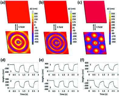
In order to predict the deformation mechanics, we schematically reproduced the design of our system in a nonlinear finite element model. For this study, we used the Marc Mentat software with a coupled electrostatic-structural analysis.40 More details can be found in Supplementary Note S1 (ESI†). Three different ITO patterns are used to generate three different textures: concentric circles with a valley at the center (CC1, Fig. 1d), concentric circles with a hill at the center (CC2, Fig. 1e) and an array of hills (ArC, Fig. 1f). Upon application of the electric field, the coating contracts above the electrodes and expands above the gap areas in-between the electrodes. Consequently, the surface topography changes from flat and smooth to a shape that matches the pattern of the ITO electrodes underneath (Fig. 2a–c and Movies S1–S3, ESI†). The width of the electrode lines, gap distances and radii of the circles are all 30 μm. In our previous research we have demonstrated that periodic electrode patterns with these proportions yield the best results due to an optimized balance in electrically activated surface area (capacitance) and maximum flow-distance of the viscoelastic material.32 In the ArC electrode pattern, circles are packed in a hexagonal lattice to obtain the highest density of hills in the surface texture. Deformation scales with the quadratic of the applied voltage.34 In the simulations, the electric field is applied at a typical voltage of 150 V and a frequency of 1 Hz. Next, the simulated responses of the coatings are monitored as a function of time at two adjacent locations: above the ITO electrode and above the gaps (Fig. 2d–f). The responses obtained from the CC1 and CC2 textures show deformation in the opposite direction with height differences of 600 nm, while the ArC texture produces hills with height differences of 780 nm. The difference between the deformation amplitude of ArC textures and CC1 or CC2 textures is caused by the different shapes of the ITO electrode. The ratio ITO/glass in terms of surface area is larger for ArC textures, resulting in a larger capacitance. Furthermore, each hill created in the ArC texture is pushed upwards from all directions, while a ring in the CC1 or CC2 textures is pushed upwards from only two directions. The FEM model is also used to predict the deformation mechanics of other complex ITO patterns that are more challenging to create experimentally. The results from these simulations are presented in Supplementary Note S2 and Fig. S1 (ESI†).2.3. Experimental analysis of the surface topographies
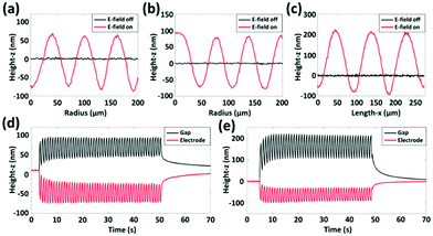
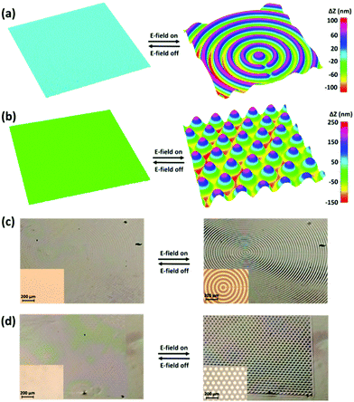
The previously discussed FEM simulations demonstrate how different electrode structures can be employed to obtain surface dynamics with complex deformation figures. Now, the predictions from our simulations are verified experimentally, by monitoring the surface topography of the coatings with digital holographic microscopy (DHM). The results indicate that we obtain a reasonably good agreement between experiment and simulation. The experiments demonstrate how the surface texture changes in-time as the electric signal is provided at a potential difference of 150 V and a frequency of 1 Hz. The chosen voltage and frequency give the optimal deformation results regarding the amplitude as well as kinetics, which are acquired from our foregoing publication.34 In accordance with our simulations, the CC1 pattern creates concentric circles with a valley at the center (Supplementary Note S3, Fig. S2 and Movie S4, ESI†), while the CC2 pattern results in concentric circles with a hill at the center (Fig. 3a and Movie S5, ESI†). Similarly, the ArC texture gives rise to an array of hexagonally packed hills (Fig. 3b and Movie S6, ESI†). Furthermore, we use a regular video camera to record the macroscopic effects of the surface deformations (Fig. 3c, d and Movies S7, S8, ESI†). The camera is placed at an angle with respect to the normal of the surface, to capture the diffuse light that is reflected. Again, the initial surface is smooth and the pattern of ITO underneath the surface is hardly distinguishable. Next, the electric field is applied and the change in the texture of the surface is clearly visible. The change of the surface topography is also recorded with an optical microscope in the reflection mode to show how the reflection of collimated light from the top gold layer changes (inset of Fig. 3c, d and Movies S9, S10, ESI†). The gloss and reflective properties of the gold surface combined with the drastic change in surface topography are essential to obtain a visible change in the texture of the coating.Next, we analyze the surface deformation by comparing profile plots of the surface before and after application of the electric field. The profile plots from CC1 and CC2 textures are obtained from the center of the pattern and follow the radius outward (Fig. 4a and b). In these figures, the z = 0 line corresponds to the reference height at zero voltage. Contraction takes place above the ITO electrode, while expansion occurs in the gap areas in-between resulting in total height differences of 150 nm. The profile plot from the ArC texture covers three neighboring hills and shows total height differences of 300 nm (Fig. 4c). The experimentally determined height differences are significantly smaller than those from our FEM simulations. This large difference is most likely caused by the resistance in the electrical circuit which results in a lower voltage output. From our FEM model we can estimate that the effective potential difference in our device is 75 V. Based on the exact correspondence between modeled and experimental deformations generated in the past, we anticipate that the experimental deformation can be further enhanced, e.g. by selecting thicker ITO layers to reduce the resistance. To continue the analysis, we investigate the oscillating behavior of the CC1 and CC2 textures by monitoring the time-resolved electro-mechanic response of the coating above the ITO electrode and the gap areas in-between (Fig. 4d). At a frequency of 1 Hz, the surface dynamics reach a steady state after the first four periods, at which point the structure oscillates 90 nm in height. After removal of the electric field, the surface relaxes back to its original flat shape in 40 seconds. The dynamics of the ArC textures show slightly different behavior (Fig. 4e). At a frequency of 1 Hz, the surface dynamics now reach a steady state after six periods, which is caused by the larger scale of the deformation. The height change of the hills is 170 nm during the oscillations, while the relaxation of the surface still takes 40 seconds after removal of the electric field.
 | ||
| Fig. 4 Details of the surface deformations and dynamics as obtained from DHM measurements. (a) The 2D profile of the concentric circles with a valley at the center, corresponding to Fig. 2a. The profile is taken from the center of the pattern and follows the radius outward. (b) The 2D profile of the concentric circles with a hill at the center, corresponding to Fig. 2b. The profile is taken from the center of the pattern and follows the radius outward. (c) The 2D profile with the array of hills, corresponding to Fig. 2c. The profile is taken over three neighboring hills. (d) Dynamics of the surface topographies at a frequency of 1 Hz for a pattern of concentric circles. (e) Dynamics of the surface topographies at a frequency of 1 Hz for a pattern with an array of circles. | ||
3. Conclusions
In conclusion, we have presented a method to obtain dynamic and reversible textural changes in the surface of a dielectric elastomer coating under an AC electric field. The pattern of the textures is controlled by the pattern of the ITO electrode, hidden underneath the surface of the elastomer. The height of the micro-structures is controlled by the electric field strength and can oscillate at a frequency between 0 and 5 Hz. Finite element method simulations are applied to support our experimental results and predict that further enhancement of the deformation is possible by reducing the resistances within our electrical circuit. The simulations can also be used to predict the results of experiments with complex ITO patterns and electric circuits to obtain more interesting surface textures. The optical effects of the changing surface structures are demonstrated microscopically and macroscopically.We expect that this work makes an important step in the development of actuator- and soft robotics related applications to control, just to mention a few, surface tribology for robotic handling, particle mitigation for self-cleaning and cell growth in biomedical systems.
4. Experimental section
4.1. Materials
Glass substrates with the patterned ITO electrodes were provided by South China Normal University. The poly(dimethyl-siloxane) (PDMS) silicone elastomer and curing agent (Sylgard 184) were obtained from Dow Corning.4.2. Sample preparation
The PDMS curing agent was added to the silicone elastomer at a concentration of 2 wt% to obtain a soft and flexible network. After thorough mixing of the two components, the trapped air in the sample was removed under reduced pressure. Prior to use, the interdigitated ITO substrates with various patterns were cleaned by ultrasonication for 20 min in acetone and isopropanol respectively and dried with nitrogen flow. The PDMS mixture was applied on the substrates by spin-coating at 7000 rpm for 2 min, which produced a coating thickness of 8 μm. The resulting layer of PDMS was cured overnight at 70 °C. After subjecting the PDMS surface to a 10 minutes UV–ozone treatment, a thin layer of gold (10 nm) was sputter-coated on top of the PDMS layer at a current of 30 mA for 18 s.4.3. Characterization
The alternating electric field with a square pulse function was provided by a function generator (Tektronix AFG3252). The electric signal from the function generator was then amplified with an amplifier (Falco Systems WMA-300). The output voltage was measured with an oscilloscope (Keysight InfiniiVision DSO-X 3032T). The surface topographies were measured with a Digital Holography Microscope (Lyncée Tec.). The thickness of the samples was measured by an interferometer (Fogale Nanotech Zoomsurf). The electric field-induced surface dynamics of the coatings were simulated in 3D using Marc Mentat 2014.0.0.Author contributions
D. L. and D. J. B. designed the project and wrote the manuscript. F. L. L. V. performed the experiments and simulations, and wrote the manuscript.Funding statement
The results presented are part of research programs financed by the Dutch Research Council (NWO), Klein project: OCENW.KLEIN.345, and Startup project: STU.019.007.Conflicts of interest
All authors declare no conflict of interest.Notes and references
- M. M. Koura, The Effect of Surface Texture on Friction Mechanisms, Wear, 1980, 63(1), 1–12 CrossRef.
- J. Chen, S. Mwenifumbo, C. Langhammer, J. P. McGovern, M. Li, A. Beye and W. O. Soboyejo, Cell/Surface Interactions and Adhesion on Ti-6AI-4V: Effects of Surface Texture, J. Biomed. Mater. Res., Part B, 2007, 82(2), 360–373 CrossRef CAS PubMed.
- A. K. Geim, S. V. Dubonos, I. V. Grigorieva, K. S. Novoselov, A. A. Zhukov and S. Y. Shapoval, Microfabricated Adhesive Mimicking Gecko Foot-Hair, Nat. Mater., 2003, 2(7), 461–463 CrossRef CAS PubMed.
- D. Attinger, C. Frankiewicz, A. R. Betz, T. M. Schutzius, R. Ganguly, A. Das, C.-J. Kim and C. M. Megaridis, Surface Engineering for Phase Change Heat Transfer: A Review, MRS Energy Sustainability, 2014, 11–40 Search PubMed.
- Y. H. Lee, J. K. Schuh, R. H. Ewoldt and J. T. Allison, Enhancing Full-Film Lubrication Performance Via Arbitrary Surface Texture Design, J. Mech. Des., 2017, 139(5), 1–13 Search PubMed.
- P. R. Seré, J. D. Culcasi, C. I. Elsner and A. R. Di Sarli, Relationship between Texture and Corrosion Resistance in Hot-Dip Galvanized Steel Sheets, Surf. Coat. Technol., 1999, 122(2–3), 143–149 CrossRef.
- A. Khellouki, J. Rech and H. Zahouani, The Effect of Abrasive Grain's Wear and Contact Conditions on Surface Texture in Belt Finishing, Wear, 2007, 26381–26387 Search PubMed.
- S. C. Baker-Finch and K. R. McIntosh, Reflection of Normally Incident Light from Silicon Solar Cells with Pyramidal Texture, Prog. Photovolt.: Res. Appl., 2011, 19(4), 406–416 CrossRef CAS.
- A. Chatterjee and O. Vartanian, Neuroscience of Aesthetics, Ann. N. Y. Acad. Sci., 2016, 1369(1), 172–194 CrossRef PubMed.
- S. Koelsch, A. M. Jacobs, W. Menninghaus, K. Liebal, G. Klann-Delius, C. von Scheve and G. Gebauer, The Quartet Theory of Human Emotions: An Integrative and Neurofunctional Model, Phys. Life Rev., 2015, 13, 1–27 CrossRef PubMed.
- L. P. Kirsch, C. Urgesi and E. S. Cross, Shaping and Reshaping the Aesthetic Brain: Emerging Perspectives on the Neurobiology of Embodied Aesthetics, Neurosci. Biobehav. Rev., 2016, 62, 56–68 CrossRef PubMed.
- H. Leder, B. Belke, A. Oeberst and D. Augustin, A Model of Aesthetic Appreciation and Aesthetic Judgments, Br. J. Psychol., 2004, 95(4), 489–508 CrossRef PubMed.
- H. Leder and M. Nadal, Ten Years of a Model of Aesthetic Appreciation and Aesthetic Judgments: The Aesthetic Episode - Developments and Challenges in Empirical Aesthetics, Br. J. Psychol., 2014, 105(4), 443–464 CrossRef PubMed.
- J. Liu, E. Lughofer and X. Zeng, Could Linear Model Bridge the Gap between Low-Level Statistical Features and Aesthetic Emotions of Visual Textures?, Neurocomputing, 2015, 947–960 CrossRef CAS.
- J. Liu, E. Lughofer and X. Zeng, Aesthetic Perception of Visual Textures: A Holistic Exploration Using Texture Analysis, Psychological Experiment, and Perception Modeling, Front. Comput. Neurosci., 2015, 9, 1–14 Search PubMed.
- S. Thumfart, R. H. A. H. Jacobs, E. Lughofer, C. Eitzinger, F. W. Cornelissen, W. Groissboeck and R. Richter, Modeling Human Aesthetic Perception of Visual Textures, ACM Trans. Appl. Percept., 2011, 8, 4 Search PubMed.
- C. Redies, Combining Universal Beauty and Cultural Context in a Unifying Model of Visual Aesthetic Experience, Front. Hum. Neurosci., 2015, 9(APR), 1–20 Search PubMed.
- R. Leach, in Characterisation of Areal Surface Texture, ed. R. Leach, Springer, Teddington, 2013 Search PubMed.
- L. Blunt and X. Jiang, Assessment Surface Topography, 2003 Search PubMed.
- L. De Chiffre, P. Lonardo, H. Trumpold, D. A. Lucca, G. Goch, C. A. Brown, J. Raja and H. N. Hansen, Quantitative Characterisation of Surface Texture, CIRP Ann., 2000, 49(2), 635–652 CrossRef.
- S. Pomberger, M. Stoschka and M. Leitner, Cast Surface Texture Characterisation via Areal Roughness, Precis. Eng., 2019, 60, 465–481 CrossRef.
- Z. Dang, L. Liu, Y. Li, Y. Xiang and G. Guo, In Situ and Ex Situ PH-Responsive Coatings with Switchable Wettability for Controllable Oil/Water Separation, ACS Appl. Mater. Interfaces, 2016, 8(45), 31281–31288 CrossRef CAS PubMed.
- G. Babakhanova, H. Yu, I. Chaganava, Q. H. Wei, P. Shiller and O. D. Lavrentovich, Controlled Placement of Microparticles at the Water-Liquid Crystal Elastomer Interface, ACS Appl. Mater. Interfaces, 2019, 11(16), 15007–15013 CrossRef CAS PubMed.
- D. Liu and D. J. Broer, Self-Assembled Dynamic 3D Fingerprints in Liquid-Crystal Coatings Towards Controllable Friction and Adhesion, Angew. Chem., Int. Ed., 2014, 53(18), 4542–4546 CrossRef CAS PubMed.
- Q. Hao, W. Li, H. Xu, J. Wang, Y. Yin, H. Wang, L. Ma, F. Ma, X. Jiang and O. G. Schmidt, et al., VO2/TiN Plasmonic Thermochromic Smart Coatings for Room-Temperature Applications, Adv. Mater., 2018, 30(10), 1–5 CrossRef PubMed.
- B. Wang, X. Xue, X. Liu, P. Neuzžil, B. Ma, W. Yuan, J. Luo and C. Jiang, Switchable Wettability Applicable to Nonplanar Surfaces, Appl. Mater. Today, 2018, 271–275 CrossRef CAS.
- S. Shian and D. R. Clarke, Electrically-Tunable Surface Deformation of a Soft Elastomer, Soft Matter, 2016, 12(13), 3137–3141 RSC.
- W. Feng, D. J. Broer and D. Liu, Oscillating Chiral-Nematic Fingerprints Wipe Away Dust, Adv. Mater., 2018, 17049701 Search PubMed.
- D. Pyo, S. Ryu, K. U. Kyung, S. Yun and D. S. Kwon, High-Pressure Endurable Flexible Tactile Actuator Based on Microstructured Dielectric Elastomer, Appl. Phys. Lett., 2018, 112(6), 1–5 CrossRef.
- E. M. Henke, K. E. Wilson and I. A. Anderson, Modeling of Dielectric Elastomer Oscillators for Soft Biomimetic Applications, Bioinspiration Biomimetics, 2018, 13, 046009 CrossRef PubMed.
- M. D. Morariu, N. E. Voicu, E. Schäffer, Z. Lin and T. P. Russell, Steiner. Hierarchical structure formation and pattern replication induced by an electric field, Nat. Mater., 2003, 2, 48–52 CrossRef CAS PubMed.
- E. Schäffer, T. Thurn-Albrecht, T. P. Russell and U. Steiner, Electrically induced structure formation and pattern transfer, Nature, 2000, 403, 874–877 CrossRef PubMed.
- Y. Liu, J. Genzer and M. D. Dickey, “2D or not 2D”: Shape-programming polymer sheets, Prog. Polym. Sci., 2016, 52, 79–106 CrossRef.
- F. L. L. Visschers, H. Gojzewski, G. J. Vancso, D. J. Broer and D. Liu, Oscillating Surfaces Fueled by a Continuous AC Electric Field, Adv. Mater. Interfaces, 2019, 6(21), 1–7 Search PubMed.
- F. Visschers, D. J. Broer and D. Liu, Electric-Field Induced Oscillating Surface Waves with Programmable Shapes, Proc. SPIE, 2020, 11375, 113751F-1–113751F-10 Search PubMed.
- S. M. Ha, W. Yuan, Q. Pei, R. Pelrine and S. Stanford, Interpenetrating Polymer Networks for High-Performance Electroelastomer Artificial Muscles, Adv. Mater., 2006, 18(7), 887–891 CrossRef CAS.
- N. America, B. C. Burchfiel, P. W. Lipman, T. Parsons, G. Soc, A. Bull, A. Tovish, G. Schubert, B. P. Luyendyk and R. Pelrine, et al., High-Speed Electrically Actuated Elastomers with Strain Greater Than 100%, Science, 2000, 287, 836–840 CrossRef PubMed.
- S. Michel, X. Q. Zhang, M. Wissler, C. Löwe and G. Kovacs, A Comparison between Silicone and Acrylic Elastomers as Dielectric Materials in Electroactive Polymer Actuators, Polym. Int., 2010, 59(3), 391–399 CrossRef CAS.
- R. E. Pelrine, R. D. Kornbluh and J. P. Joseph, Electrostriction of Polymer Dielectrics with Compliant Electrodes as a Means of Actuation, Sens. Actuators, A, 1998, 64(1), 77–85 CrossRef CAS.
- MSC Software, MSC Softw. Corp., 2014 Search PubMed.
Footnote |
| † Electronic supplementary information (ESI) available. See DOI: 10.1039/d1sm00840d |
| This journal is © The Royal Society of Chemistry 2021 |


