
Optical microfiber sensor for detection of Ni2+ ions based on ion imprinting technology
Zhen
Yi
a,
Juan
Liu
 *ab,
Bin
Liu
*ab,
Huiqin
Guo
c,
Qiang
Wu
ad,
Jiulin
Shi
a and
Xingdao
He
a
*ab,
Bin
Liu
*ab,
Huiqin
Guo
c,
Qiang
Wu
ad,
Jiulin
Shi
a and
Xingdao
He
a
aJiangxi Engineering Laboratory for Optoelectronics Testing Technology, Nanchang 330063, China. E-mail: 18042@nchu.edu.cn; liubin@nchu.edu.cn
bKey Laboratory of Non-destructive Testing, Ministry of Education, Nanchang Hangkong University, Nanchang 330063, China
cKey Laboratory of Jiangxi Province for Persistent Pollutants Control and Resources Recycle, School of Environmental and Chemical Engineering, Nanchang HangKong University, Nanchang 330063, China
dDepartment of Mathematics, Physics and Electrical Engineering, Northumbria University, Newcastle Upon Tyne NE1 8ST, UK
First published on 4th January 2022
Abstract
The detection of ultralow heavy metal ion concentration is highly significant for protecting human health and maintaining the stability of the ecological environment. Herein, a microfiber interferometer chemical sensor for the detection of Ni2+ ions was proposed and experimentally demonstrated. The microfiber sensor was coated with an ion-imprinted chitosan polymer using Ni2+ as the template ion. Experimental results demonstrated a high sensitivity of 0.0454 nm nM−M for detect-ing Ni2+ in the range of 10 nM to 100 nM, and a limit of detection as low as 6.5 nM was achieved. The microfiber sensor was verified using two different non-template heavy ions, Cu2+ and Cr3+, and was determined to be highly selective to Ni2+. Furthermore, the regeneration characteristics of the sensor were experimentally assessed by three repeated adsorption–desorption cycles, and the results showed that the microfiber sensor achieved good stability without a significant loss in sensitivity. Besides, the detecting tests of Ni2+ in lake water and industrial sewage samples demonstrated the sensor's practical application. This proposed sensor has the advantages of simple configuration, high selectivity and sensitivity, fast response, and the ability to serve as a platform for water safety monitoring and remote sensing.
1. Introduction
With the continuous discharge of wastewater from the mining, chemical, agricultural, pharmaceutical, and metal processing industries, heavy metal pollution in water has become a core environmental issue.1 Heavy metal pollution poses a great threat to human health due to the carcinogenicity and toxicity of heavy metals. The World Health Organization (WHO) has published drinking water standards that provide guidelines on the acceptable content of heavy metal ions and their harm to the human body.2,3 The real-time monitoring of heavy metal ions is crucial for meeting these drinking water standards. Therefore, the study of ultralow heavy metal ion concentration detection is highly significant for protecting human health and maintaining the stability of the ecological environment. Conventional methods for heavy metal detection include atomic absorption spectrometry (AAS),4 inductively coupled plasma mass spectrometry (ICP-MS),5 spectrophotometry,6 chemiluminescence,7 and electrochemical methods.8 However, these methods are limited by expensive detection instruments, complex procedures, complicated analyte pre-treatment, and the need for trained professional workers. Furthermore, these techniques cannot be applied to long-distance and real-time detection on site. There is a growing demand for a simple, low-cost, rapid, and on-site detecting system for the remote real-time sensing of heavy metal ions.In the past decades, the development and application of optical fiber sensors have widely attracted the attention of researchers. Various microfiber sensors such as microfiber optical interferometers,9–11 microfiber gratings,12 and microfiber couplers13 have been proposed and adopted for both refractive index (RI) sensing and biosensing14,15 due to the high sensitivity caused by their evanescent waves. Optical fiber sensors are also designed and modified to detect heavy metal ions in liquids.16–18 Chi Chiu Chan et al.19–22 have done a series of studies in this field and promoted the research of optical fiber sensor in the detection of heavy metals. However, most reported optical fiber sensors have shown limited RI sensitivities, making it difficult to meet the required sensing performance for trace heavy metal detection (in the ppb and ppt range), and research on heavy ion detection using optical sensors suffers from specificity and reproducibility issues.
In recent years, ion imprinting technology (IIT), which was developed based on molecular imprinting technology, has attracted wide attention because of its high selectivity. The specific recognition of ions by IIT is achieved with ion-imprinted polymers (IIPs) that have specially constructed binding sites complementary to template ions in shape, size, and coordination.23–26 IIPs have been applied in many fields such as solid-phase extraction, chemical sensors, and membrane separation because of their high biological and chemical recognition characteristics. The general procedure for the synthesis and use of IIPs is outlined as follows: (1) a polymer is produced containing the template or target ion, which is covalently or noncovalently bound to a functional group of the host; (2) the template ion is removed from the polymer host, leaving a target-specific cavity available for rebinding; and (3) the IIP is exposed to the target-containing sample, allowing the cavity to selectively uptake the target ion from a sample.27–29
An ultrasensitive microfiber interferometer chemical sensor for Ni2+ ion concentration detection is presented in this paper. The microfiber structure used in this work is based on a single-mode tapered-no-core single-mode (STNCS) fiber sensor that generates an easily accessible evanescent field on the surface of the fiber taper. A thin film of nickel ion-imprinted chitosan (Ni2+-II-CS) polymer was deposited on the surface of the tapered waist of the microfiber by dip-coating technique. Due to the presence of amine and hydroxyl groups,19,30,31 chitosan can form a covalent bond with metallic ions. Furthermore, in cross-linked chitosan, polymeric chains are interconnected with crosslinkers, leading to the formation of a 3D network that can improve the adsorption capacity of metal ions. When hydrochloric acid is used as regenerant, the amine functional groups on the sorbents are protonated which induce the repulsive force between the adsorbed Ni2+ and NH3+ groups and as a result Ni2+ is released into the solution.32–34 This provides a theoretical basis for the regeneration of the sensor. The performance of the STNCS sensor coated with Ni2+-II-CS was tested in the Ni2+ concentration range of 10 nM to 500 nM. The selectivity of the sensor was verified using Cu2+ and Cr3+ ions, and it was found to be highly selective for Ni2+. Additionally, the sensor exhibited good reusability in Ni2+ adsorption–desorption cycle experiments. While this proposed sensor was used to detect Ni2+, it can also be used to detect other heavy ions by changing the template ion used to imprint the chitosan polymer. Furthermore, the practical applicability of the sensor for Ni2+ detection was investigated using the lake water and industrial sewage samples. This proposed microfiber interferometer chemical sensor displays great potential for heavy metal detection in environmental water analysis, process control, and remote monitoring applications.
2. Principle & simulation
Fig. 1(a) shows the schematic diagram of the microfiber interferometer. The smaller diameter of the STNCS provides a stronger evanescent field and increases the RI sensitivity. The transmission characteristics of the STNCS structure were simulated by employing the beam propagation method (BPM) based on a 2D model.10,15Fig. 1(b) shows the distributions of the optical field propagating along the STNCS structure (L1 = L3 = 8 mm, L2 = 5 mm, D = 4.8 μm) and the corresponding normalized optical intensity change at 1500 nm. The simulated spectral response and RI sensing curve are shown in Fig. 1(c) and (d), with a calculated RI sensitivity of 2275 nm per refractive index unit (RIU). This high RI sensitivity provides a guarantee for the feasibility of ultralow Ni2+ detection in this paper. In the simulation, the parameters of the no-core fiber (NCF) and single mode fiber (SMF) were chosen as: nNCF = 1.4428, nSMF∞ = 1.4507, and nSMFd = 1.4428.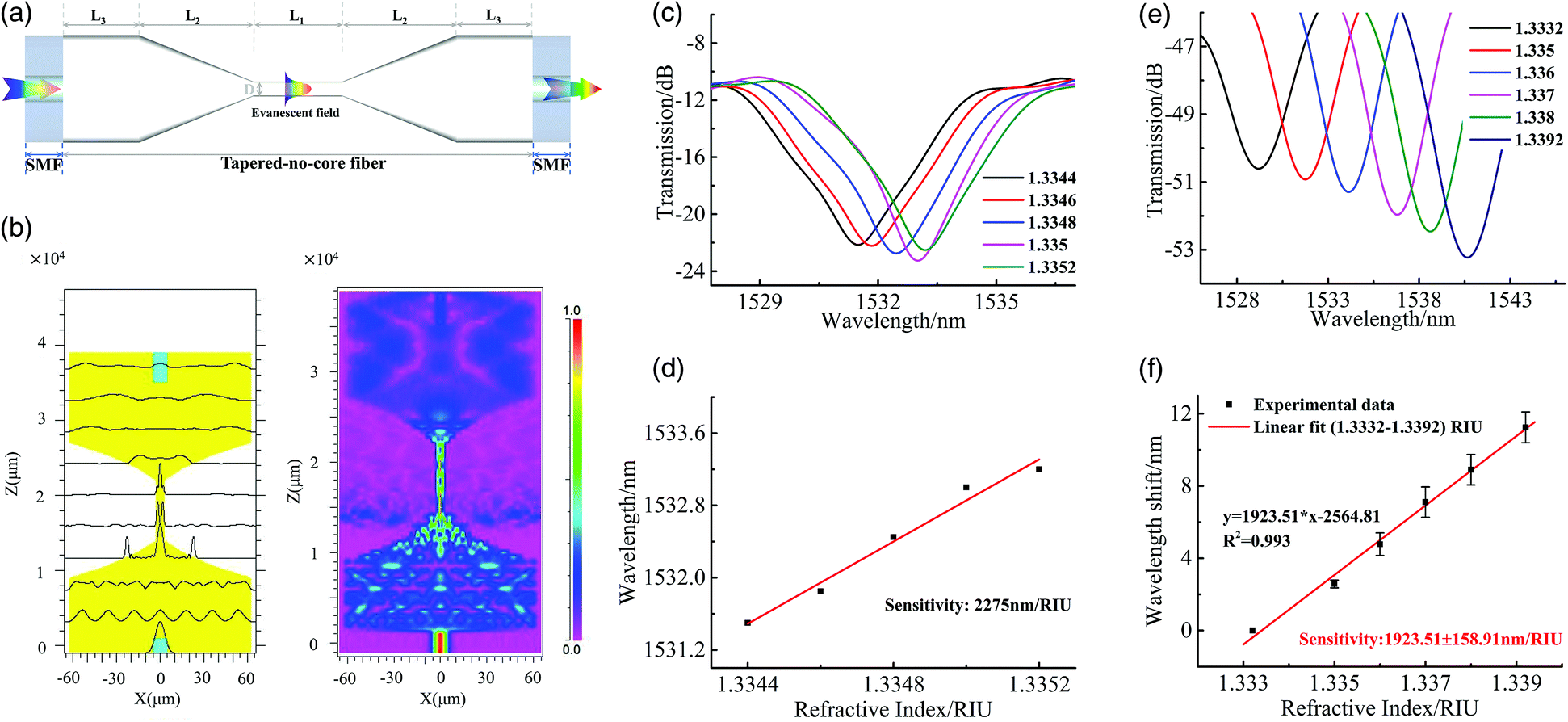 | ||
| Fig. 1 (a) Schematic diagram of the STNCS sensor. (b) Optical field distribution and normalized optical intensity propagating along the STNCS structure with a tapered waist diameter of 4.8 μm. (c) Simulated spectral response. (d) Simulated RI sensitivity predicted for the STNCS structure with 4.8 μm taper waist diameter in the RI range of about 1.334. (e) The STNCS sensor spectral response curves with different external RI values. (f) Sensitivity of the STNCS sensor to external RI (Error bars represent standard deviations for three repeated experiments). | ||
3. Experiments
3.1. Sensor fabrication
A section of 15 mm NCF (purchased from Thorlabs) was spliced between two SMFs using a fusion splicer (FSM-80S, Fujikura). A tapered region was formed by heating and pulling the NCF using a thermal pulling system (OC2010, Nanjing Jilong Optical Communication Co., Ltd). The uniformity and reproducibility of the fabricated taper were achieved by controlling the pulling speed, scanning speed, and temperature of the pulling process.3.2. RI sensing characteristics
The RI response characteristics of an STNCS optical fiber structure with a 4.255 μm waist diameter were determined. Fig. 1(e) and (f) show the experimental spectral response and the RI sensing curve, respectively. It can be observed from Fig. 1(f) that the RI sensitivity is 1923.51 nm per RIU for the RI range of 1.3332 to 1.3392. Due to the small deviation in the manufacturing process, there is an error between the experimental RI sensitivity and the simulation result (2275 nm per RIU).3.3. Preparation of ion imprinted STNCS sensor based on chitosan polymer
In this paper, a layer of crosslinked nickel-chitosan (Ni-CS) polymer was coated on the surface of the STNCS sensor by dip-coating technique. The Ni2+ ions were then chemically removed from the polymer to form a Ni2+-II-CS film. The Ni2+-II-CS synthesis scheme is shown in Fig. 2(a). For the preparation of the polymer, 1 g of chitosan was dissolved in 50 mL of 2% acetic acid solution and stirred by a homogenizer for 24 h at 1500 rounds per min. 50 mg of NiCl2 was then added to the chitosan solution, which was continuously stirred for 2 h in the same manner. To improve the mechanical properties of the chitosan, 5 mL of epichlorohydrin (ECH) was then added to the homogenized solution, which was stirred for another 4 h to facilitate crosslinking.35,36 The clean STNCS sensor was immersed in this solution and then removed at a withdrawal speed of 0.25 mm s−1 by a dip coater. This dip-coating technique achieved a uniform, high-quality crosslinked Ni-CS film on the surface of the sensor. The sensor was dried in air at room temperature for 5 min, then dried overnight in an incubator at 65 °C. | ||
| Fig. 2 (a) Ni2+-II-CS synthesis scheme. (b) Procedure for obtaining the microfiber sensor coated with Ni2+-II-CS film. (c) STNCS sensor response curves for a bare sensor, a sensor coated with Ni-CS film, and a sensor coated with Ni2+-II-CS film (after Ni2+ removal). (d) SEM image of the STNCS sensor. (e) Schematic diagram of the sensing system. | ||
The removal of Ni2+ ions from the polymer was carried out by immersing the cross-linked Ni-CS film sensor into a 1 mM hydrochloric acid (HCl) solution. This was re-peated three times, with the sensor thoroughly rinsed with deionized (DI) water between each immersion. Fig. 2(b) shows the procedure for obtaining the microfiber sensor coated with Ni2+-II-CS. Fig. 2(c) shows the spectrum response after each operation. There is an opposite wavelength shift in the chosen dip during the preparation process, indicating the formation of the Ni-CS film and the removal of Ni2+ ions form the crosslinked Ni-CS film. A scanning electron microscope (SEM) image of the tapered NCF with a waist diameter of 4.255 μm is shown in Fig. 2(d).
3.4. Experimental system
A schematic diagram of the sensing system is shown in Fig. 2(e). A broadband light source (BBS, Shenzhen FiberLake Technology. Ltd) with a wave-length range of 1250–1650 nm was used to transmit light through the STNCS sensor, and the transmitted light exiting the lead-out fiber was detected by an optical spectrum analyzer (OSA, AQ6370D) with a resolution of 0.02 nm.4. Results and discussion
4.1. Stability
After the STNCS microfiber sensor was coated with Ni2+-II-CS film, a stability test was carried out by immersing the STNCS sensor in DI water for 10 min. Fig. 3(a) shows that the variation of the dip wavelength remains relatively stable during this period. The standard deviation (σ) is below 0.098 nm, indicating the good stability of the STNCS sensor coated with Ni2+-II-CS. | ||
| Fig. 3 (a) Spectral response curves of the STNCS sensor coated with Ni2+-II-CS and immersed in DI water for 10 min (the standard deviation is 0.098 nm). (b) Spectral response curves of the STNCS sensor coated with Ni2+-II-CS to different Ni2+ ion concentrations. (c) Ni2+ ion calibration curve and linear response of the STNCS sensor coated with Ni2+-II-CS film. (d) Response time curves of the STNCS sensor coated with Ni2+-II-CS and immersed in 10 nM Ni2+ solution. (e) Spectral response of the STNCS sensor coated with Ni2+-II-CS to 10 nM Ni2+ ion solution for 15 min. (f) Response of the STNCS sensor coated with Ni2+-NII-CS to different concentrations (50 and 100 nM) of heavy metal ions (nickel, copper, and chromium). (g) Response of the STNCS sensor coated with Ni2+-II-CS to different concentrations (50 and 100 nM) of heavy metal ions (nickel, copper, and chromium). (Error bars represent standard deviations for three parallel experiments). (h) Regeneration cycle: shift in dip wavelength of the STNCS sensor coated with Ni2+-II-CS caused by sequential exposure to 50 nM Ni2+ solution and MES buffer. | ||
4.2. Sensitivity and limit of detection (LOD)
To investigate the performance of the STNCS sensor coated with Ni2+-II-CS film, a series of experiments were carried out. Solutions with different Ni2+ concentrations (10–500 nM) were prepared by diluting a highly concentrated Ni2+ solution. The spectral response of the sensor to different Ni2+ concentrations was recorded, starting from the lowest (10 nM) to the highest (500 nM) concentration. Fig. 3(b) shows that the spectral dip shifts to longer wavelengths as the Ni2+ concentration increases. When the Ni2+ ions enter the domain of the sensing surface, the effective RI of the sensing surface changes due to chelation between Ni2+ and the binding sites in the ion-imprinted layer. A higher Ni2+ concentration means that more binding sites will be occupied, which results in a greater change in the effective RI. Fig. 3(c) shows the wavelength shift vs. Ni2+ concentration curve. The sensor exhibits a linear response in the range of 0–100 nM with a Ni2+ detection sensitivity of 0.0454 nm nM−1, but as the concentration of Ni2+ increases from 100 nM to 500 nM, the wavelength gradually stops shifting. This is because at lower concentrations, there is a sufficient number of binding sites available for the Ni2+ ions. However, the number of binding sites available per Ni2+ ion decreases as the Ni2+ ion concentration increases. The LOD of the proposed sensor is evaluated using 3σ/k, where σ is the standard deviation of blank signals, and k is the slope of the linear calibration plot.37 The LOD thus calculated was determined to be 6.5 nM. This value is much lower than the recommended Ni2+ limit of 1.19 μM for drinking water specified by the WHO.2,204.3. Equilibrium time on Ni2+ adsorption
Equilibrium time is important for the control of the experimental measurement time. The effect of the contact time for Ni2+ binding process at concentration (10 nM) is described in Fig. 3(d). And Fig. 3(e) shows the spectral response of the STNCS sensor coated with Ni2+-II-CS to 10 nM Ni2+ ion solution for 15 min. As observed, the wavelength shift increases greatly with the contact time up to 7 min and then onwards increases slightly. The wavelength shift reaches the saturation with the contact time of 10 min, implying that equilibrium was reached. So the contact time of 10 min was sufficient to be selected for the experimental measurement time. This long response time is caused by the much lower concentration of Ni2+ ions in this experiment compared with other reported work.19 Higher solution concentrations mean more ions per unit volume, a greater probability of collision between binding sites and ions, more ion collisions per unit time, and faster interaction.4.4. Selectivity
To determine the selectivity of the proposed fiber sensor, three heavy metal (nickel, copper, and chromium) ions were tested at two different concentrations (50 and 100 nM). For comparison, nickel non-ion-imprinted chitosan (Ni2+-NII-CS) was also prepared at the same condition but without addition of Ni2+. First, the spectral response of an STNCS fiber sensor coated with Ni2+-NII-CS to different heavy metal concentrations was recorded. The spectral dip wavelength obtained for the three heavy metal ions shifts toward longer wavelengths as concentration increases, as shown in Fig. 3(f). There are no significant wavelength shift deviations among the three ions for this non-specific sensor. An identical selectivity test was carried out using the STNCS fiber sensor coated with Ni2+-II-CS film. The bar chart in Fig. 3(g) shows that this sensor is highly selective toward Ni2+ ions compared to Cu2+ and Cr3+ ions. The binding sites complementary to the shape and size of the template ions are only compatible with Ni2+ ions, while Cu2+ and Cr3+ ions do not bind to the binding sites. The small wavelength shift seen for the Cu2+ and Cr3+ ions may be due to their binding with the Ni2+-II-CS layer.Table 1 provides a summary of the measured wavelength shifts of the STNCS sensors coated by Ni2+-NII-CS film and Ni2+-II-CS film. The wavelength shifts observed using the sensor coated with the Ni2+-NII-CS film for Ni2+ concentrations of 50 nM and 100 nM are 1.25 nm and 2.11 nm, respectively. For the sensor coated with Ni2+-II-CS film, the respective wavelength shifts are 2.54 nm and 3.96 nm. For 50 nM and 100 nM Cu2+, the wavelength shifts of the Ni2+-NII-CS film are 1.29 nm and 1.97 nm, while those of the Ni2+-II-CS film are 0.56 nm and 0.61 nm, respectively. A similar trend is seen for the Cr3+ solutions. These results demonstrate that Ni2+ ion-imprinted binding sites improve the affinity of the sensor for Ni2+ and reduce its affinity for other heavy metal ions, a clear indication of the proposed sensor's high selectivity toward Ni2+ ions.
| Concentration (nM) | Wavelength shift(nm) | |||
|---|---|---|---|---|
| Ni2+ | Cu2+ | Cr3+ | ||
| Ni2+-NII-CS film | 50 | 1.25 ± 0.010 | 1.29 ± 0.10 | 1.39 ± 0.16 |
| 100 | 2.11 ± 0.04 | 1.97 ± 0.13 | 1.76 ± 0.09 | |
| Ni2+-II-CS film | 50 | 2.25 ± 0.10 | 0.56 ± 0.07 | 0.59 ± 0.06 |
| 100 | 4.57 ± 0.13 | 0.61 ± 0.07 | 0.65 ± 0.07 | |
4.5. Regeneration
The amine groups in chitosan are protonated when pH < 4, resulting in the unbinding and release of Ni2+. Based on this phenomenon, the reusability of the STNCS sensor coated with Ni2+-II-CS film was investigated. In this experiment, a 50 nM Ni2+ solution was used. Fig. 3(h) shows that during the Ni2+ binding process, the wavelength shift is stable after 7 min. After adsorption, the fiber sensor was regenerated by washing with MES buffer (pH = 3.5), which shifted the dip wavelength back to its initial value. Three repeated adsorption–desorption cycles were carried out. The wavelength shift deviation after the second and third cycles was calculated to be 0.06 nm and 0.05 nm, respectively. Therefore, it can be concluded that the proposed sensor exhibits relatively good regeneration adsorption efficiency and can be repeatedly used.4.6. Analytical application
In order to further demonstrate the proposed sensor's practical application, the lake water samples from Nanchang Hangkong university and industrial sewage samples from Jiujiang Electroplating Industrial Park were employed as example for tests. All the water samples were filtered with a 0.22 μm syringe filter to remove the particles.Six lake water samples with the same ion concentration (100 nM) were prepared for the analysis use, by spiking with Ni2+, Cu2+, Cr3+, Pb2+, K+, Na+, respectively. The mixed solution (100 nM) was obtained by adding the above metal ions except nickel ions into the lake water sample. The measurements were carried out by immersing the proposed sensor in the solutions for 15 min in turn. And the sensor was cleaned with DI water before the next test. To verify the sensor's selectivity in complex samples, the spectral changes after adding nickel ions to the mixed solution were observed and recorded. The results obtained are presented in Fig. 4(a) and (b). It can be seen that there is a huge shift due to the presence of Ni2+.
 | ||
| Fig. 4 (a) Spectral response of the STNCS sensor coated with Ni2+-II-CS to the mix and the mix excess added Ni2+ sample. (b) Shift in dip wavelength of the STNCS sensor coated with Ni2+-II-CS caused by exposure to various targets in lake water sample: blank, the 100 nM excess of other cations including Ni2+, Cu2+, Cr3+, Pb2+, K+, Na+, mix and mix added Ni2+. (c) Calibration of the Ni2+ content in electroplating wastewater sample by colorimetric test paper and (d) shift in dip wavelength of the STNCS sensor coated with Ni2+-II-CS caused by exposure to different concentrations of Ni2+ in electroplating wastewater sample. (Error bars represent standard deviations for three parallel experiments). | ||
Besides, the application of constructed sensor for Ni2+ detection in complex industrial sewage sample was investigated. The industrial sewage samples were taken from the untreated wastewater pool of nickel-plating enterprises in Jiujiang wanlitong electroplating industrial park. As shown in Fig. 4(c), the concentration of Ni2+ of sewage samples after ten times dilution is estimated to be 1 mg L−1. The original wastewater sample at a concentration of approximately 10 ppm (mg L−1) was then diluted to 103, 104 fold (10 ppb, 1 ppb). After that, the response performance of the senor to Ni2+ in the obtained two groups of the solution was investigated. Fig. 4(d) shows the kinetic absorption process of binding Ni2+. And the total wavelength shifts achieved are 2.1 nm and 3.1 nm, respectively, which is consistent with the wavelength shift trend in DI water. Note that the higher Ni2+ concentration corresponds with a faster response time (about 6 min for 10 ppb and 8 min for 1 ppb). According to the Emission standard of pollutants for copper, nickel, cobalt industry for China (GB 25467-2010), the maxi-mum concentration of Ni2+ allowed in areas prone to environmental severe pollution problems is 100 ppb. The detection limit of the sensor, which is lower than 1 ppb, clearly meets the standard. From the analysis of the test results of lake water and sewage samples, the proposed sensor has good selectivity and high detection sensitivity in practical application.
5. Conclusions
In this work, we proposed a microfiber sensor coated with an ion-imprinted chitosan polymer to detect heavy metal ions. The performance of this sensor was experimentally demonstrated using Ni2+ as the template ion and an STNCS microfiber structure with a 4.255 μm waist diameter as the sensing platform. The sensor exhibits a Ni2+ detection sensitivity of 0.0454 nm nM−1 in the linear range of 0–100 nM, and a LOD as low as 6.5 nM. The selectivity of the proposed sensor was assessed by measuring two different non-template heavy ions, Cu2+ and Cr3+. The sensor has a significantly lower response to the two nontarget heavy ions, demonstrating its high selectivity toward Ni2+. Furthermore, the regeneration characteristics of the sensor were experimentally determined by three repeated adsorption–desorption cycles, showing that the sensor has good stability without a significant loss in sensitivity. Moreover, the sensor was suitable for the determination of Ni2+ in environmental water and electroplating wastewater. The excellent performance of this proposed sensor demonstrates great potential for fast and accurate quantification in practical applications such as water quality analysis, remote analysis. Next, we plan to develop an integrated multichannel all-fiber optofluidic sensing platform38 for real-time detection of target ions.Author contributions
Zhen Yi: investigation, formal analysis, writing – original draft; Juan Liu: conceptualization, methodology, writing – review &editing; Bin Liu: project administration, data curation, resources; Huiqin Guo: methodology, resources; Qiang Wu: project administration, writing – review &editing; Jiulin Shi: validation, visualization; Xingdao He: funding acquisition, supervision.Conflicts of interest
The authors declare no competing financial interest.Acknowledgements
This work was jointly supported by National Natural Science Foundation of China (NSFC) (62163029, 61865013, 62065013); Natural Key Research and Development Project from the Ministry of Science and Technology (grant no. 2018YFE0115700); Science and Technology Project of Jiang-xi Education Department (grant no. GJJ180518); Nanchang Hangkong University Graduate Student Innovation special fund project (grant no. YC2020-S523).References
- L. Fan, C. Luo, Z. Lv, F. Lu and H. Qiu, Colloids Surf., B, 2011, 88(2), 574–581 CrossRef CAS PubMed.
- WHO, Guidelines for Drinking Water Quality, 4th edn, 2011, pp. 307–442 Search PubMed.
- M. Jaishankar, T. Tseten, N. Anbalagan, B. B. Mathew and K. N. Beeregowda, Interdiscip. Toxicol., 2014, 7(2), 60–72 CrossRef PubMed.
- G. Jarzynska and J. Falandysz, J. Environ. Sci. Health, Part A: Toxic/Hazard. Subst. Environ. Eng., 2011, 46(6), 569–573 CrossRef CAS PubMed.
- X. Chen, C. Han, H. Cheng, Y. Wang, J. Liu, Z. Xu and L. Hu, J. Chromatogr. A, 2013, 1314(11), 86–93 CAS.
- E. Pehlivan and S. Cetin, J. Hazard. Mater., 2009, 163(1), 448–453 CrossRef CAS PubMed.
- K. Tsukagoshi, M. Hashimoto, R. Nakajima and A. Arai, Anal. Sci., 2000, 16(11), 1111–1112 CrossRef CAS.
- F. Bakhtiarzadeh and S. A. Ghani, J. Electroanal. Chem., 2008, 624(1–2), 139–143 CrossRef CAS.
- H. Luo, Q. Sun, X. Li, Z. Yan, Y. Li, D. Liu and L. Zhang, Opt. Lett., 2015, 40(21), 5042–5045 CrossRef CAS PubMed.
- H. Yang, J. Liu, B. Liu, C. Luo, Z. Yi, L. Ma, S.-P. Wan, A. R. Pike, Y. Q. Fu, Q. Wu and X. He, IEEE Access, 2020, 8, 220755–220761 Search PubMed.
- J. Wang, Y. Liao, S. Wang and X. Wang, Opt. Express, 2018, 19(26), 24843 CrossRef PubMed.
- Y. Zhang, B. Lin, S. C. Tjin, H. Zhang, G. Wang, P. Shum and X. Zhang, Opt. Express, 2010, 18, 26345–26350 CrossRef CAS PubMed.
- K. Li, T. Zhang, G. Liu, N. Zhang, M. Zhang and L. Wei, Appl. Phys. Lett., 2016, 109, 101101 CrossRef.
- L. Chen, Y. K. Leng, B. Liu, J. Liu, S. P. Wan, T. Wu, J. Yuan, L. Shao, G. Gu, Y. Q. Fu, H. Xu, Y. Xiong, X. D. He and Q. Wu, Sens. Actuators, B, 2020, 320, 128283 CrossRef CAS.
- R. Kumar, Y. Leng, B. Liu, J. Zhou, L. Shao, J. Yuan, X. Fan, S. Wan, T. Wu, J. Liu, R. Binns, Y. Q. Fu, W. P. Ng, G. Farrell, Y. Semenova, H. Xu, Y. Xiong, X. He and Q. Wu, Biosens. Bioelectron., 2019, 145, 111563 CrossRef CAS PubMed.
- B. Gu, M.-J. Yin, A. P. Zhang, J.-W. Qian and S. He, Sens. Actuators, B, 2011, 160, 1174–1179 CrossRef CAS.
- Y.-N. Zhang, L. Zhang, B. Han, P. Gao and Q. Wu, Sens. Actuators, B, 2018, 272, 331–339 CrossRef CAS.
- W. B. Ji, S. H. K. Yap, N. Panwar, L. L. Zhang, B. Lin, K. T. Yong, S. C. Tjin, W. J. Ng and M. B. A. Majid, Sens. Actuators, B, 2016, 237, 142–149 CrossRef CAS.
- R. Raghunandhan, L. H. Chen, H. Y. Long, L. L. Leam, P. L. So, X. Ning and C. C. Chan, Sens. Actuators, B, 2016, 233, 31–38 CrossRef CAS.
- Z. Q. Tou, T. W. Koh and C. C. Chan, Sens. Actuators, B, 2014, 202, 185–193 CrossRef CAS.
- Z.-W. Ding, R. Ravikumar, C.-L. Zhao, L.-H. Chen and C. C. Chan, J. Lightwave Technol., 2019, 37(10), 2246–2252 CAS.
- J. Yang, L. H. Chen, Y. Zheng, X. Dong, R. Raghunandhan, P. L. So and C. C. Chan, Sens. Actuators, B, 2016, 230, 353–358 CrossRef CAS.
- J. Lu, Y. Y. Qin, Y. L. Wu, M. J. Meng, Y. S. Yan and C. X. Li, Environ. Sci.: Water Res. Technol., 2019, 5, 1626–1653 RSC.
- X. Gao, J. Liu, M. Li, C. Guo, H. Long, Y. Zhang and L. Xin, Chem. Eng. J., 2020, 385, 123897 CrossRef CAS.
- W. Liu, Z. An, L. Qin, M. Wang, X. Liu and Y. Yang, Chem. Eng. J., 2021, 411, 128477 CrossRef CAS.
- J. Qi, B. Li, X. Wang, Z. Zhang, Z. Wang, J. Han and L. Chen, Sens. Actuators, B, 2017, 251, 224–233 CrossRef CAS.
- V. Lenoble, K. Laatikainen, C. Garnier, B. Angeletti, B. Coulomb, T. Sainio and C. Branger, Chem. Eng. J., 2016, 304, 20–28 CrossRef CAS.
- W. René, V. Lenoble, M. Chioukh and C. Branger, Sens. Actuators, B, 2020, 319, 128252 CrossRef.
- J. J. BelBruno, Chem. Rev., 2019, 119(1), 94–119 CrossRef CAS PubMed.
- Q. Zia, M. Tabassum, H. Gong and J. Li, J. Fiber Bioeng. Inform., 2019, 12(3), 103–128 CrossRef.
- A.-H. Chen, S.-C. Liu, C.-Y. Chen and C.-Y. Chen, J. Hazard. Mater., 2008, 154(1–3), 184–191 CrossRef CAS PubMed.
- M. Monier, D. A. A.-Latif and Y. G. A. E.-Reash, J. Colloid Interface Sci., 2016, 469, 344–354 CrossRef CAS PubMed.
- B. Kannamba, K. L. Reddy and B. V. AppaRao, J. Hazard. Mater., 2010, 175(1–3), 939–948 CrossRef CAS PubMed.
- L. Fan, C. Luo, Z. Lv, F. Lu and H. Qiu, Colloids Surf., B, 2011, 88, 574–581 CrossRef CAS PubMed.
- R. A. A. Muzzarelli, Carbohydr. Polym., 2009, 77, 1–9 CrossRef CAS.
- K. Inoue, Y. Baba and K. Yoshizuka, Bull. Chem. Soc. Jpn., 1993, 66, 2915–2921 CrossRef CAS.
- Y. Cui, F. Chen and X.-B. Y, Biosens. Bioelectron., 2019, 135, 208–215 CrossRef CAS PubMed.
- W. Li, H. Wang, R. Yang, D. Song, F. Long and A. Zhu, Anal. Chim. Acta, 2018, 1040, 112–119 CrossRef CAS PubMed.
| This journal is © The Royal Society of Chemistry 2022 |