 Open Access Article
Deciphering the dual functions of a silicon dioxide protective layer in regulating lithium-ion deposition†
Tianlai
Wu
ab,
Weicai
Zhang
 ab,
Jiawen
Cai
a,
Mingtao
Zheng
 ab,
Hang
Hu
ab,
Xiaoyuan
Yu
ab,
Hang
Hu
ab,
Xiaoyuan
Yu
 ab,
Dan
Shao
*c,
Yong
Xiao
 ab,
Yingliang
Liu
 *ab and
Yeru
Liang
 *ab
*ab
aKey Laboratory for Biobased Materials and Energy of Ministry of Education, Guangdong Provincial Engineering Technology Research Center for Optical Agriculture, College of Materials and Energy, South China Agricultural University, Guangzhou, 510642, China. E-mail: tliuyl@scau.edu.cn; liangyr@scau.edu.cn
bGuangdong Laboratory of Lingnan Modern Agriculture, Guangzhou, 510642, China
cGuangdong Key Laboratory of Battery Safety, Guangzhou Institute of Energy Testing, Guangzhou, 511447, China. E-mail: shaod1005@163.com
First published on 6th May 2022
Abstract
Silicon dioxide (SiO2) is widely applied as a protective layer of lithium (Li) metal, as it can suppress the growth of Li dendrites and prolong cycling life. However, fundamental understanding of how the SiO2 protective layer affects Li-ion deposition behavior is still limited. Such knowledge would be very desirable for the practical use of Li metal. Herein, a systematic study investigating the role of SiO2 as a protective layer for realizing uniform Li-ion deposition is described. Based on the successful construction of model materials, it was found that the SiO2 protective layer offers dual functions in improving Li deposition behaviors. The SiO2 protective layer can assist in the rapid transfer of Li ions from the electrolyte to the Li metal surface, while SiO2 near the Li metal surface can be used as lithiophilic sites to guide Li nucleation. Consequently, Li metal protected by SiO2 favors homogeneous Li nucleation/growth and successfully inhibits the formation of dendrites during prolonged cycling. An impressive long cycling stability for over 400 h with a low potential hysteresis was obtained in a symmetrical cell with protected Li, and an extended cycling life was achieved for protected Li when coupled with LiNi0.5Co0.2Mn0.3O2 cathode.
Currently, lithium-ion batteries dominate the market as power sources for numerous devices and applications. However, the energy density of lithium-ion batteries is approaching its theoretical limit. As such, these batteries cannot meet the increasing demands of modern society. In order to tackle the low capacity of graphite anodes in lithium-ion batteries, lithium (Li) metal has been proposed as the ultimate anode material due to its high theoretical specific capacity (3860 mA h g−1) and low electrochemical potential (−3.04 V versus the standard hydrogen electrode).1 However, the growth of Li dendrites during the charge/discharge process can pierce the separator and cause the battery to short circuit, resulting in safety hazards.2 Furthermore, the formation of “dead Li” as well as negative reactions between Li metal and the liquid electrolyte can lead to a low coulombic efficiency (CE) and poor cycling stability.3
Gigantic efforts have been devoted to overcoming these chronic problems associated with Li metal anodes.4–7 Among various strategies, building a protective layer is considered to be a promising way to suppress Li dendrite growth and improve the CE and cycling stability.8–11 Until now, various types of materials, such as ceramic metal oxides,12 lithium compounds,13 and polymers,14 have been shown to form efficient protective layers on Li metal. Among these materials, silicon dioxide (SiO2) is emerging as one of the most compelling candidates, because of its impressive merits such as high chemical/electrochemical stability, exceptional mechanical strength, high ionic conductivity, easy processability and tunability.15 As a protective layer, SiO2 has been found to suppress side reactions and stabilize the electrode/electrolyte interface.16,17 In addition, homogeneous Li deposition can be achieved by the introduction of a SiO2 layer, leading to the formation of dendrite-free Li metal and improved electrochemical performance.18 Despite these achievements, research that attempts to gain a fundamental understanding of how the SiO2 protective layer affects Li-ion deposition behavior has been limited. Therefore, identifying the effect of the SiO2 protective layer on the regulation of Li-ion deposition is essential for guiding the interfacial design and practical use of Li metal.
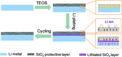
Herein, a systematic insight into the role of SiO2 as a protective layer in realizing uniform Li-ion deposition is proposed. Based on the successful construction of a SiO2 protective layer on the surface of Li metal, it is found that the SiO2 protective layer offers dual functions in improving Li deposition behaviors (Fig. 1). On one hand, the SiO2 protective layer facilitates Li-ion transport from the electrolyte to the Li metal surface, giving rise to a much lower interface impedance, far higher exchange current density and reduced interfacial transfer barrier. On the other hand, the SiO2 protective layer that is close to the Li metal surface exhibits Li reactivity. This SiO2 layer, which has high Li affinity, can be used as a lithiophilic layer to promote Li nucleation. Benefiting from this dual functional feature, the Li metal protected by SiO2 favors homogeneous Li nucleation/growth and successfully restrains the growth of dendrites during prolonged cycling. As a consequence, a prolonged cycling stability of 400 h, with a smooth voltage plateau for symmetrical cells, is achieved, which further endows the Li‖LiNi0.5Co0.2Mn0.3O2 full cells with improved capacity retention of up to 81.4% after 100 cycles and a high CE of above 98.6% for 100 cycles.
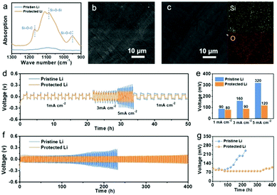
To investigate the role of the SiO2 protective layer in regulating Li-ion deposition, a SiO2 layer was constructed on a Li metal surface, by treating Li metal with tetraethoxysilane (eqn (S1), ESI†).16Fig. 2a shows the Fourier-transform infrared (FTIR) spectrum of the protected Li and pristine Li. Pristine Li delivers no obvious absorption band between 900 and 1300 cm−1. In comparison, protected Li exhibits peaks at around 950 and 1167 cm−1, which are attributed to Si–O–C. In addition, a peak between 1000 and 1090 cm−1 corresponding to the characteristic peaks of Si–O–Si in SiO2 is observed, indicating that a SiO2 layer has been successfully constructed on the Li surface.19 X-ray diffraction (XRD) of protected Li was conducted to further confirm the successful construction of SiO2. As shown in Fig. S1 (ESI†), a weak ‘bread’-shaped diffraction peak appears near 28.8°, which is assigned to SiO2 (PDF#14-0654). Scanning electron microscopy (SEM) was performed to investigate the micro-morphology of the as-prepared Li metal. As shown in Fig. 2b, obvious protrusions and grooves can be found on the surface of pristine Li, which will result in uneven Li deposition due to the “tip effect”.20–22 After treatment with tetraethoxysilane, the protected Li shows a relatively smooth surface, because some protrusions and grooves on the surface of Li metal have been dissolved during the formation of the SiO2 protective layer (Fig. 2c). The thickness of the as-formed SiO2 protective layer is about 58 μm (Fig. S2, ESI†). Energy dispersive spectroscopy (EDS) was carried out to probe the distribution of SiO2 in protective layer. It was found that Si and O elements are evenly distributed on the surface of protected Li, indicating the uniform distribution of SiO2 on protected Li.
To confirm that the SiO2 protective layer can inhibit the growth of Li dendrites, electrochemical characterizations of Li‖Li symmetrical cells were performed. Rate performances of Li‖Li symmetrical cells using pristine Li and protected Li were studied at current densities of 1, 3, and 5 mA cm−2 with a fixed Li deposition capacity of 1 mA h cm−2 (Fig. 2d). The relationship between current density and polarization voltage is shown in Fig. 2e. It is obvious that pristine Li delivers a larger polarization voltage than that of protected Li at different current densities. In particular, the polarization voltages of pristine Li are more than 1.8 times and 2.7 times larger than those of protected Li at the current densities of 3 and 5 mA cm−2, respectively. The Li‖Li symmetrical cells were further cycled at 1.0 mA cm−2 with a capacity of 1.0 mA h cm−2 to evaluate the stability during the plating/stripping process (Fig. 2f and g). Pristine Li delivers an increasing polarization hysteresis at the beginning of 100 h (100 mV), which contributes to the rapid generation of “dead Li” and the consumption of electrolyte. Subsequently, the polarization hysteresis reaches a peak of 240 mV and a sudden voltage drop at 220 h, indicating an internal short circuit due to the growth of Li dendrites. In contrast, protected Li shows a remarkable cycling stability over 400 h with a flat voltage plateau due to the SiO2 protective layer. The large change of interfacial resistance after different cycles also confirms the instability of pristine Li in a carbonate-based electrolyte, while protected Li can maintain a reliable interfacial resistance (Fig. S3, ESI†). Moreover, an improved electrochemical performance for protected Li can also be found at current densities of 0.5 mA cm−2 and 0.5 mA h cm−2 (Fig. S4, ESI†). These results illustrate that SiO2 can effectively stabilize Li metal to suppress Li dendrite formation.
To illuminate the mechanism behind the function of SiO2 in regulating Li-ion deposition, it is necessary to understand the process of Li-ion deposition on Li anodes. In general, at the beginning of Li-ion deposition, Li ions first need to diffuse through a solid-electrolyte interphase (SEI) and obtain electrons on the surface of Li metal to subsequently form initial nuclei.23 The Li-ion behavior in the SEI and the initial nucleation behavior are the critical factors that affect the Li-ion deposition morphology.24,25 Therefore, the function of SiO2 in regulating both Li-ion transport behavior and Li-ion nucleation behavior are examined in the following section.
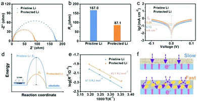
As is well known, during the process of Li-ion transport, the diffusion barrier and ionic conductivity of the SEI are the key factors affecting the morphology of Li deposition according to the space-charge model and “mosaic” model.26,27 To investigate the function of SiO2 in Li-ion transport behavior, electrochemical impedance spectroscopy (EIS) analysis of Li‖Li symmetric cells was performed. As shown in Fig. 3a and b, protected Li displays a lower interfacial resistance of 87.1 Ω, compared to that of pristine Li (167.0 Ω), suggesting that the construction of a SiO2 protective layer can promote the transmission of Li ions. The reduced interfacial resistance of protected Li compared to that of pristine Li after depositing Li with different capacities also confirms the faster Li-ion mobility in the protected Li (Fig. S5, ESI†). Similar kinetics of Li migrating behaviors was further revealed by the exchange current density (I0). As is well known, I0 can be calculated by using the Tafel relationship yields, which can be obtained from the cyclic voltammetry profiles (Fig. 3c and Fig. S6, ESI†). It was found that the I0 of protected Li (0.20 mA cm−2) is more than 1.5 times larger than that of pristine Li (0.13 mA cm−2), indicating the faster kinetics of Li transport for protected Li. The activation energy (Ea), which represents Li-ion diffusion in the SEI, was obtained by fitting the respective temperature-dependent resistances with the Arrhenius equation (Fig. 3d and Fig. S7, ESI†).23 As shown in Fig. 3e, Ea decreases from 47.5 kJ mol−1 in pristine Li to 45.1 kJ mol−1 in protected Li. Benefiting from the function of SiO2 in promoting Li-ion transport, the Li-ion transport from the electrolyte to the Li metal surface is easier and quicker, which contributes to the formation of a uniform and dense Li deposition film (Fig. 3f).
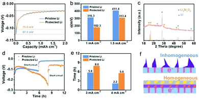
After Li ions pass through the interfacial layer, they start to nucleate on the surface of Li metal and Li grows on the existing Li nuclei. The Li growth structure depends heavily on the initial nucleation behavior, which thus affects the final deposition morphology. The nucleation overpotential (η) in the process of initial nucleation is a key parameter that can be used to evaluate the lithiophilicity of the substrate, and a better lithiophilicity favors the formation of a uniform deposition film.28 To investigate the lithiophilicity of SiO2 in protected Li, η was measured by directly plating Li on pristine Li and protected Li at a current density of 0.4 mA cm−2. As displayed in Fig. 4a, a sharp voltage drop to −0.1243 V is observed on protected Li due to the starting of Li nucleation, and the voltage rises slowly and maintains a relatively stable voltage platform, reflecting the growth process of Li. The difference between the sharp voltage and the stable voltage is the η of protected Li (75.0 mV). By comparison, pristine Li delivers a larger η of 97.1 mV. In addition, the voltage-capacity curves of pristine Li and protected Li at current densities of 1.0 and 1.5 mA cm−2 were investigated (Fig. S8, ESI†), and the corresponding η values are summarized in Fig. 4b. Obviously, the η value of protected Li is lower than that of pristine Li at different current densities, indicating that protected Li can induce Li nucleation. Specifically, at the beginning of Li deposition, electrons would be concentrated on the Li metal interface and Li ions can transport through the SiO2 protective layer due to the low electronic conductivity and high ionic conductivity of the SiO2 protective layer. As a consequence, the SiO2 protective layer close to the Li metal surface can be used as lithiophilic sites to induce Li nucleation due to its reactivity with Li.29
To confirm the reactivity of SiO2 with Li, FTIR was used to analyze the composition of protected Li after plating Li at a capacity of 0.5 mA h cm−2 (Fig. S9, ESI†). A peak at around 1000 cm−1 corresponding to the Si–O bond of lithiated SiO2 can be observed.30 The XRD pattern shows new characteristic peaks of Li2Si2O5 for protected Li after Li deposition (Fig. 4c). These results confirm that the SiO2 layer on protected Li delivers a reactivity with Li (eqn (S2), ESI†).31 As is well known, the introduction of lithiophilic sites is an effective way to achieve uniform Li-ion deposition and to inhibit the formation of Li dendrites.32 To verify the function of SiO2 on protected Li in promoting uniform deposition of Li, constant current polarization tests of pristine Li and protected Li were carried out at high current densities (Fig. 4d and e and Fig. S10, ESI†).33 At a current density of 3 mA cm−2, a sudden drop in voltage for pristine Li at about 5.8 h resulted from a short circuit due to the growth of Li dendrites, while protected Li could maintain a long Li deposition time of about 8.0 h. Similarly, protected Li exhibited a persistent deposition time (5.6 h) compared to that of pristine Li (2.2 h) when the current density was increased to 4 mA cm−2. These results demonstrate that the SiO2 protective layer design can promote the uniform deposition of Li to alleviate the growth of Li dendrites (Fig. 4f).
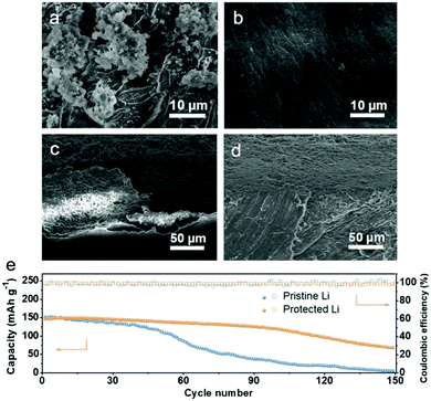
To directly unlock the function of SiO2 in regulating Li-ion deposition, the morphologies of the Li anodes after cycling were observed using SEM, as shown in Fig. 5. Pristine Li exhibits a rough surface with dendrites after 100 h cycles, while protected Li maintains a smooth surface, demonstrating that the uniform deposition of Li and the inhibition of Li dendrite growth were successfully realized by the SiO2 protective layer (Fig. 5a and b). From the cross-section SEM image in Fig. 5c, a thick and porous Li layer can be found in pristine Li, which enlarges the contact area between pristine Li and the electrolyte, thereby accelerating the consumption of the electrolyte and the formation of more “dead Li”. In addition, the large gap between the Li layer and Li metal surface will also further aggravate the subsequent uneven Li deposition behavior on pristine Li. In contrast, the SiO2 protective layer is in firm contact with Li metal without any gaps, indicating that the dual function of the SiO2 protective layer jointly promotes the uniform deposition of Li (Fig. 5d).
The protected Li was coupled with commercial LiNi0.5Co0.2Mn0.3O2 (NCM523) cathode to further evaluate the practical application of the SiO2 protective layer in stabilizing the Li metal anode. As displayed in Fig. 5e and Fig. S11 (ESI†), similar initial discharge specific capacities can be observed for the pristine Li‖NCM523 cell and protected Li‖NCM523 cell, but the capacity of the pristine Li‖NCM523 cell begins to decline sharply at the 50th cycle and drops to 29.3 mAh cm−1 after 100 cycles. In comparison, the protected Li‖NCM523 cell maintains a long cycle stability, retaining 81.4% of the initial capacity after 100 cycles. Moreover, the improved rate performance of the protected Li‖NCM523 cell also confirms the superiority of the SiO2 protective layer (Fig. S12, ESI†).
Conclusions
In summary, the SiO2 protective layer on Li metal shows dual functions in regulating Li-ion deposition, which significantly stabilizes the Li metal anode/electrolyte interface and alleviates the growth of Li dendrites. On one hand, the SiO2 protective layer with high ionic conductivity can assist the rapid migration of Li ions from the electrolyte to the Li metal surface, so as to prevent the formation of a huge space charge. On the other hand, SiO2 close to the Li metal surface can be used as lithiophilic sites to induce Li nucleation and thus to inhibit the uncontrolled deposition of Li. Benefiting from these dual functions, the symmetrical cell using protected Li can achieve stable cycling for 400 h with a flat voltage plateau, and the cell coupled with NCM523 cathode shows improved electrochemical properties. This in-depth study on the function of the SiO2 protective layer provides new insights into Li protection.Conflicts of interest
The authors have no conflicts of interest to disclose.Acknowledgements
The authors gratefully acknowledge financial support from the projects of Guangdong Key Laboratory of Battery Safety (2019B121203008), the National Natural Science Foundation of China (51972121, 21671069), and the Guangdong Basic and Applied Basic Research Foundation (2019A1515011502).References
- F. Liu, R. Xu, Y. C. Wu, D. T. Boyle, A. K. Yang, J. W. Xu, Y. Y. Zhu, Y. S. Ye, Z. A. Yu, Z. W. Zhang, X. Xiao, W. X. Huang, H. S. Wang, H. Chen and Y. Cui, Nature, 2021, 600, 659–663 CrossRef CAS.
- D. Koo, B. Kwon, J. Lee and K. T. Lee, Chem. Commun., 2019, 55, 9637–9640 RSC.
- L. L. Li, S. Y. Li and Y. Y. Lu, Chem. Commun., 2018, 54, 6648–6661 RSC.
- M. Chen, J. H. Zheng, Y. J. Liu, O. W. Sheng, Z. J. Ju, G. X. Lu, T. F. Liu, Y. Wang, J. W. Nai, Q. Wang and X. Y. Tao, Adv. Funct. Mater., 2021, 31, 2102228 CrossRef CAS.
- B. Tang, L. X. Gao, J. Q. Liu, S. H. Bo, Z. J. Xie, J. P. Wei and Z. Zhou, J. Mater. Chem. A, 2020, 8, 18087–18093 RSC.
- N. Tolganbek, A. Serikkazyyeva, S. Kalybekkyzy, M. Sarsembina, K. Kanamura, Z. Bakenov and A. Mentbayeva, Mater. Adv., 2022, 3, 3055–3069 RSC.
- Y. J. Liu, Y. X. Wu, J. L. Zheng, Y. Wang, Z. J. Ju, G. X. Lu, O. W. Sheng, J. W. Nai, T. F. Liu, W. K. Zhang and X. Y. Tao, Nano Energy, 2021, 82, 105723 CrossRef CAS.
- G. H. Moon, H. J. Kim, I. S. Chae, S. C. Park, B. S. Kim, J. Y. Jang, H. S. Kim and Y. S. Kang, Chem. Commun., 2019, 55, 6313–6316 RSC.
- B. Shen, T. W. Zhang, Y. C. Yin, Z. X. Zhu, L. L. Lu, C. Ma, F. Zhou and H. B. Yao, Chem. Commun., 2019, 55, 7703–7706 RSC.
- Y. R. Liang, Y. Xiao, C. Yan, R. Xu, J. F. Ding, J. Liang, H. J. Peng, H. Yuan and J. Q. Huang, J. Energy Chem., 2020, 48, 203–207 CrossRef.
- Z. J. Ju, G. X. Lu, O. W. Sheng, H. D. Yuan, S. Q. Zhou, T. F. Liu, Y. J. Liu, Y. Wang, J. W. Nai, W. K. Zhang and X. Y. Tao, Nano Lett., 2022, 22, 1374–1381 CrossRef CAS.
- R. Xu, Y. Xiao, R. Zhang, X. B. Cheng, C. Z. Zhao, X. Q. Zhang, C. Yan, Q. Zhang and J. Q. Huang, Adv. Mater., 2019, 31, 1808392 CrossRef PubMed.
- K. Chen, R. Pathak, A. Gurung, E. A. Adhamash, B. Bahrami, Q. Q. He, H. Qiao, A. L. Smirnova, J. J. Wu, Q. Q. Qiao and Y. Zhou, Energy Storage Mater., 2019, 18, 389–396 CrossRef.
- B. Zhu, Y. Jin, X. Z. Hu, Q. H. Zheng, S. Zhang, Q. J. Wang and J. Zhu, Adv. Mater., 2017, 29, 1603755 CrossRef.
- J. Y. Kim, A. Y. Kim, G. C. Liu, J. Y. Woo, H. S. Kim and J. K. Lee, ACS Appl. Mater. Interfaces, 2018, 10, 8692–8701 CrossRef CAS.
- G. A. Umeda, E. Menke, M. Richard, K. L. Stamm, F. Wudl and B. Dunn, J. Mater. Chem., 2011, 21, 1593–1599 RSC.
- C. Wu, F. H. Guo, L. Zhuang, X. P. Ai, F. P. Zhong, H. X. Yang and J. F. Qian, ACS Energy Lett., 2020, 5, 1644–1652 CrossRef CAS.
- Y. R. Hu, Y. R. Zhong, L. M. Qi and H. L. Wang, Nano Res., 2020, 13, 3230–3234 CrossRef CAS.
- H. M. Jiang, Z. Zheng, Z. M. Li and X. L. Wang, Ind. Eng. Chem. Res., 2006, 45, 8617–8622 CrossRef CAS.
- H. Liu, D. C. Peng, T. Y. Xu, K. D. Cai, K. N. Sun and Z. H. Wang, J. Energy Chem., 2021, 53, 412–418 CrossRef.
- W. Liu, D. C. Lin, A. L. Pei and Y. Cui, J. Am. Chem. Soc., 2016, 138, 15443–15450 CrossRef CAS PubMed.
- T. Foroozan, F. A. Soto, V. Yurkiv, S. Sharifi-Asl, R. Deivanayagam, Z. N. Huang, R. Rojaee, F. Mashayek, P. B. Balbuena and R. Shahbazian-Yassar, Adv. Funct. Mater., 2018, 28, 1705917 CrossRef.
- R. Xu, C. Yan, Y. Xiao, M. Zhao, H. Yuan and J. Q. Huang, Energy Storage Mater., 2020, 28, 401–406 CrossRef.
- Z. J. Huang, G. M. Zhou, W. Lv, Y. Q. Deng, Y. B. Zhang, C. Zhang, F. Y. Kang and Q. H. Yang, Nano Energy, 2019, 61, 47–53 CrossRef CAS.
- X. R. Chen, Y. X. Yao, C. Yan, R. Zhang, X. B. Cheng and Q. Zhang, Angew. Chem., Int. Ed., 2020, 59, 7743–7747 CrossRef CAS PubMed.
- H. J.-S. Sand, Philos. Mag., 1901, 1, 45–79 CAS.
- Y. M. Zhao, G. X. Li, Y. Gao, D. W. Wang, Q. Q. Huang and D. H. Wang, ACS Energy Lett., 2019, 4, 1271–1278 CrossRef CAS.
- A. L. Pei, G. Y. Zheng, F. F. Shi, Y. Z. Li and Y. Cui, Nano Lett., 2017, 17, 1132–1139 CrossRef CAS PubMed.
- P. Xue, C. Sun, H. P. Li, J. J. Liang and C. Lai, Adv. Sci., 2019, 6, 1900943 CrossRef CAS.
- H.-r D. Y. Zhu, Y. Li, Y. Z. Li, X. M. Xu and A. H. Lu, Acta Mineral. Sin., 2019, 39, 173–182 Search PubMed.
- R. Pathak, K. Chen, A. Gurung, K. M. Reza, B. Bahrami, F. Wu, A. Chaudhary, N. Ghimire, B. Zhou, W. H. Zhang, Y. Zhou and Q. Q. Qiao, Adv. Energy Mater., 2019, 9, 1901486 CrossRef.
- T. L. Wu, Y. Y. Wang, W. C. Zhang, K. X. Lu, J. Y. Tan, M. T. Zheng, Y. Xiao, Y. L. Liu and Y. R. Liang, J. Energy Chem., 2022, 71, 324–332 CrossRef.
- S. S. Li, Y. Huang, C. Luo, W. H. Ren, J. Yang, X. Li, M. S. Wang and H. J. Cao, Chem. Eng. J., 2020, 399, 125687 CrossRef CAS.
Footnote |
| † Electronic supplementary information (ESI) available. See DOI: https://doi.org/10.1039/d2ma00201a |
| This journal is © The Royal Society of Chemistry 2022 |

