 Open Access Article
A′–A–π–D–π–A–A′ extended small-molecule photovoltaic donor based on fluorene-diketopyrrolopyrrole with an end-group fluorination effect†
Yang
Liu
,
Lunxiang
Yin
*,
Bao
Xie
 ,
Chang
Liu
and
Yanqin
Li
 *
*
School of Chemical Engineering, Dalian University of Technology, Linggong Road 2, Dalian, P. R. China. E-mail: lxyin@dlut.edu.cn; liyanqin@dlut.edu.cn
First published on 27th June 2022
Abstract
Three novel small-molecule donors (SMDs), namely Flu(DPP)2, Flu(DPPsF)2 and Flu(DPPdF)2, were designed and synthesized to comprehensively investigate the synergistic effect of extended conjugation and end-group fluorination on photoelectric properties. Firstly, acceptor-π-donor-π-acceptor (A–π–D–π–A) small molecule Flu(DPP)2 was constructed with alkylated fluorene, ethynyl functionalized thiophene, and diketopyrrolopyrrole (DPP) as the donor, π-bridge bond and acceptor units, respectively. Subsequently, two novel A′–A–π–D–π–A–A′ extended small-molecules Flu(DPPsF)2 and Flu(DPPdF)2 were constructed by introducing monofluoro and difluoro substituted phenyl groups at the end group of Flu(DPP)2. Compared with Flu(DPP)2, Flu(DPPsF)2 and Flu(DPPdF)2 show broader absorption. Moreover, due to the introduction of a fluorine substituted phenyl group, the band gap becomes narrower, and difluoro-terminal substituted Flu(DPPdF)2 shows a narrower electrochemical band gap (ECVg) than monofluoro-terminal substituted Flu(DPPsF)2. More importantly, bulk heterojunction (BHJ) organic photovoltaic (OPV) devices were prepared using Flu(DPP)2, Flu(DPPsF)2 and Flu(DPPdF)2 as donors mixed with PC61BM, respectively. As a result, the devices based on Flu(DPPsF)2 and Flu(DPPdF)2 achieve higher power conversion efficiency (PCE) than those based on Flu(DPP)2, which are 4.39% and 4.74%, respectively. This work shows that the synergistic strategy with A′–A–π–D–π–A–A′ extended molecular and end-group fluorination provides crucial guidance for the design of novel photovoltaic materials with outstanding photoelectric properties.
Introduction
In recent years, organic solar cells (OSCs) have attracted extensive attention because of their flexibility, light-weight and low cost.1–3 With the innovation and optimization of materials and devices, the power conversion efficiency (PCE) of OSCs has exceeded 20%, showing broad application prospects.4 As we all know, the active layer is an important component of OSCs.5,6 Generally, both polymers and small molecules could be used as donor materials in active layers.7 Compared with polymer donor materials, small molecules have obvious advantages such as well-defined chemical formula, tunable molecular structure, easy purification and high reproducibility.8–10 However, in recent years, nonfullerene acceptor materials have attracted more attention, and the development of small molecule donor (SMD) materials seems to be relatively lagging behind. Therefore, it is necessary to develop novel SMDs with superior performance and low cost.Fluorene, a tricyclic fused aromatic compound, has a good planar rigid structure, which is conducive to capturing more photons in the visible and near-infrared wavelengths.11,12 By introducing fluorene into the molecular structure, the energy band gap of the material can be adjusted and the film-forming property can be improved. At the same time, the solubility of the material can be adjusted by introducing a long side alkyl chain into the fluorene unit.13,14 Surprisingly, the weak electron-donating ability of fluorene leads to a deeper highest occupied molecular orbital (HOMO) level, which provides great potential for devices to obtain a high open circuit voltage (VOC) based on fluorene as the electron-donating unit.15–17 For instance, in 2014, the devices based on DCAO3TF composed of fluorene with a high VOC of 1.07 V were obtained by the Chen group,15 which is one of the highest VOC in OSCs based on the donor/PCBM active layer at that time. Moreover, Hu et al. reported three A–D–A SMDs based on a fluorene-core modified by various terminal groups, and then devices based on these materials showed high VOC in the range from 0.97 to 1.07 V.18 However, the development of organic small molecule donor materials based on fluorene is still insufficient. In view of the above excellent high VOC properties of fluorene-based small molecules, the construction of organic SMDs containing fluorene is urgently needed at present.
The push–pull conjugated system composed of electron-rich and electron-deficient groups connected by a conjugated π-bridge has been widely used in the design of organic photovoltaic materials.19,20 Each fragment plays an important role in adjusting the energy level of the molecular orbital and the optical transition of the push–pull system.21 Among many acceptor units, DPP is outstanding for the following reasons: (a) good planarity;22 (b) intermolecular interactions, such as hydrogen bonding and π–π interactions, contribute to high charge carrier mobility23–25 and (c) small molecules based on DPP usually exhibit strong absorption in the visible and even the near-infrared spectrum.26,27 Therefore, DPP based molecules usually have a narrow band gap and a deep HOMO energy level.28 The solubility of DPP-based molecules could be increased by alkyl substitution at the 2,5-position of the lactam nitrogen, which is conducive to the formation of good film morphology with fullerene acceptors.29 Based on these significant advantages, DPP units have great potential in the design of organic photovoltaic materials.
Sometimes minor modifications to the molecular structure can lead to significant improvements in the photovoltaic properties of materials. Therefore, a reasonable modification strategy plays an important role in the innovation of new materials. In order to improve the short-circuit current density (JSC), various modification strategies are used to redshift the absorption spectrum as much as possible, such as expanding the conjugation of the central nucleus to increase its electron donating ability,30–32 or inserting conjugated fragments between the D-unit and the A-unit.33–35 In addition, the absorption spectrum of compounds can also be broadened by extending the conjugation of molecules or increasing the electron acceptance ability of the A-unit.36–40 Fluorine, due to its small atomic radius and high electronegativity, has strong electron-withdrawing properties.41 The introduction of a fluorine atom into the end group can not only broaden the light absorption and reduce the molecular energy level, but also enhance the interaction between molecules through C–F⋯H, C–F⋯S and C–F⋯π interactions, which are helpful in optimizing the morphology of the active layer.42–44 However, the systematic research using two or more synergetic strategies still needs to be further explored.
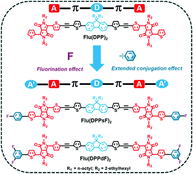
Inspired by the above discussion, three small molecules, namely Flu(DPP)2, Flu(DPPsF)2 and Flu(DPPdF)2 were designed and synthesized to investigate the extended conjugation and fluorination effects. The molecular design concept and chemical structures of the three compounds are shown in Scheme 1. For comparison, the reference molecule Flu(DPP)2 was constructed with alkylated fluorene as the donor (D) unit, DPP as the acceptor (A) unit, and ethynyl functionalized thiophene as the π-bridge bond. Subsequently, two novel A′–A–π–D–π–A–A′ extended small-molecules Flu(DPPsF)2 and Flu(DPPdF)2 were constructed by introducing monofluoro and difluoro substituted phenyl groups at the end of Flu(DPP)2. Density functional theory (DFT) and time-dependent DFT (TD-DFT) calculations were used to predict the ground-state geometry, energy levels, electron-density distribution, and optical absorption characteristics of the three compounds. Compared with Flu(DPP)2, Flu(DPPsF)2 and Flu(DPPdF)2 show wider absorption. Moreover, due to the introduction of the fluorine substituted phenyl group, the band gap becomes narrower and difluoro-terminal substituted Flu(DPPdF)2 shows a narrower electrochemical band gap than monofluoro-terminal substituted Flu(DPPsF)2. In addition, Flu(DPPdF)2 has a deeper HOMO energy level than Flu(DPPsF)2, which is expected to obtain high VOC in organic photovoltaic devices (OPVs). It is worth mentioning that the bulk heterojunction (BHJ) OPVs were prepared using Flu(DPP)2, Flu(DPPsF)2 and Flu(DPPdF)2 as donors mixed with PC61BM, respectively. As a result, the devices based on Flu(DPPsF)2 and Flu(DPPdF)2 achieve higher power conversion efficiencies (PCEs) than the devices based on Flu(DPP)2, which are 4.39% and 4.74% respectively. This work shows that this extended molecular design and fluorine substitution strategy have great potential in the development of new OPV materials.
Experiments and methods
Reagents and materials
All reagents and materials mentioned in this article were purchased from commercial suppliers and can be used directly. Toluene and tetrahydrofuran (THF) were dried with sodium/benzophenone under a nitrogen atmosphere before use.Device fabrication and characterization
The conventional device structure of ITO/PEDOT:PSS/organic active layer/Al was used to prepare solution-treated BHJ OSCs. Indium tin oxide (ITO) glass substrates were cleaned by ultrasonication for 30 minutes in deionized water, methanol, acetone, toluene and isopropanol in an appropriate sequence. The substrate was then dried in an infrared oven for 20 minutes. Subsequently, poly(3,4-ethylenedioxy-thiophene):poly(styrene sulfonate) (PEDOT:PSS) was spin-coated on the glass substrate at a rate of 4000 rpm for 60 seconds. After baking at 140 °C for 20 minutes, the glass substrate was transferred to a glove box filled with nitrogen (N2) for spin-coating of the organic active layer. Subsequently, the mixed solution of the SMDs and PC61BM in chloroform (9 mg mL−1) was spin-coated on the ITO/PEDOT:PSS substrate at 1000 rpm for 60 seconds. Finally, under a vacuum of 10−4 Pa, a thin layer of aluminum (80 nm) was deposited on the active layer as the cathode, and eight individual devices with an effective area of 5.0 mm2 were obtained. The characteristics of hole mobility (μh) and electron mobility (μe) were obtained by the device structures of the ITO/PEDOT:PSS/organic active layer/Au and ITO/ZnO/organic active layer/Al, respectively. A thin gold layer (80 nm) was deposited on the active layer by thermal evaporation. The zinc oxide (ZnO) dispersion was spin-coated on the glass substrate at a rate of 3000 rpm for 60 seconds. The charge carrier mobility was calculated by the space charge limited current (SCLC) method using the following equation:45,46J = (9/8) ε0εrμ (V2/L3), where J, ε0, εr, μ, V and L are the current density, the permittivity of free space, the relative permittivity of the material, the hole mobility and electron mobility, the effective voltage and active layer thickness, respectively.Measurements and characterization
1H-NMR and 13C-NMR spectra were recorded using a Bruker AVANCE II 500 MHz and a 125 MHz spectrometer with TMS as the internal standard and CDCl3 as the solvent. A MALDI Micro MX spectrometer was used to measure high resolution mass spectra (HRMS). Ultraviolet-visible (UV-Vis) absorption spectra were obtained using an Agilent Cary 5000 spectrometer in CHCl3 solution and in thin films. Cyclic voltammetry (CV) measurements were performed on a CHI610D electrochemical workstation from CH Instruments. Tests were carried out in 0.1 M Bu4NBF4/CH2Cl2 solution and under a nitrogen atmosphere at a scan rate of 100 mV s−1. Ferrocene–ferrocenium (Fc/Fc+) was used as an internal standard, and a conventional three-electrode cell with a glassy carbon working electrode, an Ag/Ag+ (Ag in 0.1 M acetonitrile solution of AgNO3) reference electrode, and a platinum wire counter electrode was used. The HOMO and LUMO energy level value, and the electrochemical band gap were calculated according to the following empirical equations:47–49 HOMOCV/LUMOCV = −[EOX/red − Eferrocene1/2 + 4.8]eV, where Eferrocene1/2 = 0.05 eV versus Ag/Ag+, Eox is the measured onset oxidation potential and Ered is the measured onset reduction potential. Thermogravimetric analysis (TGA) was performed using a TA Instruments Q50 thermogravimetric analyzer at a heating rate of 10 °C min−1 under nitrogen. The current density–voltage (J–V) characteristics of the OSCs were measured with a computer controlled Keithley 2400 Source Measure Unit under simulated AM 1.5G illumination with an intensity of 100 mW cm−2. The external quantum efficiency (EQE) spectra of OSCs were measured using a solar cell spectral response measurement system QE-R3-011 (Enli Technology Co., Ltd., Taiwan). The J–V characteristics of the hole-only and the electron-only devices were measured with a Keithley 2400 Source Measure Unit system in the dark.Synthesis and characterization
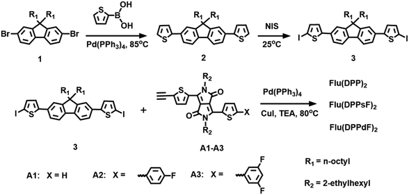
The synthetic routes for the compounds Flu(DPP)2, Flu(DPPsF)2, and Flu(DPPdF)2 are shown in Scheme 2. Compound 1 was prepared according to the previously reported procedures18 and the synthetic procedure of DPP-based intermediates (compounds A1, A2 and A3) can be found in the ESI.†![[thin space (1/6-em)]](https://www.rsc.org/images/entities/char_2009.gif) :
:![[thin space (1/6-em)]](https://www.rsc.org/images/entities/char_2009.gif) 3, v/v) to afford a brown solid (300 mg, 67%). M.p.: 139–141 °C. 1H-NMR (500 MHz, CDCl3, ppm) δ 8.93 (d, J = 3.8 Hz, 2H), 8.91 (d, J = 4.1 Hz, 2H), 7.71 (d, J = 7.9 Hz, 2H), 7.64 (d, J = 5.0 Hz, 2H), 7.60 (d, J = 8.0 Hz, 2H), 7.56 (s, 2H), 7.39 (d, J = 4.1 Hz, 2H), 7.33 (q, J = 3.8 Hz, 4H), 7.30–7.27 (m, 2H), 4.10–3.97 (m, 8H), 2.06–1.98 (m, 4H), 1.95–1.84 (m,4H), 1.41–1.24 (m, 32H), 1.20–1.05 (m, 20H), 0.92–0.85 (m, 24H), 0.80 (t, J = 7.1 Hz, 6H), 0.70 (m, 4H). 13C-NMR (125 MHz, CDCl3, ppm) δ 161.66, 161.61, 152.00, 147.93, 140.79, 140.69, 140.68, 139.24, 135.60, 135.40, 134.03, 132.85, 132.59, 130.82, 129.81, 128.51, 127.92, 125.13, 123.24, 120.99, 120.45, 120.13, 108.79, 108.11, 91.32, 87.05, 55.40, 46.08, 45.97, 40.31, 39.16, 39.10, 31.78, 30.24, 30.23, 30.17, 30.15, 29.94, 29.19, 29.16, 28.37, 28.34, 26.92, 23.78, 23.56, 23.08, 22.60, 14.04, 14.03, 10.50, 10.49. HRMS(MALDI-TOF):1646.7747, [M+] (calcd for C101H122N4O4S6: 1646.7990).
3, v/v) to afford a brown solid (300 mg, 67%). M.p.: 139–141 °C. 1H-NMR (500 MHz, CDCl3, ppm) δ 8.93 (d, J = 3.8 Hz, 2H), 8.91 (d, J = 4.1 Hz, 2H), 7.71 (d, J = 7.9 Hz, 2H), 7.64 (d, J = 5.0 Hz, 2H), 7.60 (d, J = 8.0 Hz, 2H), 7.56 (s, 2H), 7.39 (d, J = 4.1 Hz, 2H), 7.33 (q, J = 3.8 Hz, 4H), 7.30–7.27 (m, 2H), 4.10–3.97 (m, 8H), 2.06–1.98 (m, 4H), 1.95–1.84 (m,4H), 1.41–1.24 (m, 32H), 1.20–1.05 (m, 20H), 0.92–0.85 (m, 24H), 0.80 (t, J = 7.1 Hz, 6H), 0.70 (m, 4H). 13C-NMR (125 MHz, CDCl3, ppm) δ 161.66, 161.61, 152.00, 147.93, 140.79, 140.69, 140.68, 139.24, 135.60, 135.40, 134.03, 132.85, 132.59, 130.82, 129.81, 128.51, 127.92, 125.13, 123.24, 120.99, 120.45, 120.13, 108.79, 108.11, 91.32, 87.05, 55.40, 46.08, 45.97, 40.31, 39.16, 39.10, 31.78, 30.24, 30.23, 30.17, 30.15, 29.94, 29.19, 29.16, 28.37, 28.34, 26.92, 23.78, 23.56, 23.08, 22.60, 14.04, 14.03, 10.50, 10.49. HRMS(MALDI-TOF):1646.7747, [M+] (calcd for C101H122N4O4S6: 1646.7990).
![[thin space (1/6-em)]](https://www.rsc.org/images/entities/char_2009.gif) :
:![[thin space (1/6-em)]](https://www.rsc.org/images/entities/char_2009.gif) 5, v/v) to give a dark solid (167 mg, 38%). M.p.: 174–175 °C. 1H-NMR (500 MHz, CDCl3, ppm) δ 8.97 (d, J = 4.0 Hz, 2H), 8.91 (d, J = 4.1 Hz, 2H), 7.69 (d, J = 7.9 Hz, 2H), 7.64 (dd, J1 = 8.6 Hz, J2 = 5.2 Hz, 4H), 7.61–7.55 (m, 4H), 7.38 (dd, J1 = 9.8 Hz, J2 = 4.1 Hz, 4H), 7.33 (q, J = 3.9 Hz, 4H), 7.12 (t, J = 8.5 Hz, 4H), 4.12–3.99 (m, 8H), 2.06–1.99 (m, 4H), 1.97–1.88(m, 4H), 1.41–1.25 (m, 32H), 1.21–1.06 (m, 20H), 0.95–0.87 (m, 24H), 0.80 (t, J = 7.1 Hz, 6H), 0.71 (m, 4H). 13C-NMR (125 MHz, CDCl3, ppm) δ 164.09, 162.10, 161.63, 161.49, 152.00, 148.78, 147.92, 140.78, 140.30, 138.86, 137.14, 135.38, 134.02, 132.85, 132.58, 130.87, 129.47, 128.75, 127.96, 127.89, 127.84, 125.14, 124.50, 123.23, 121.01, 120.46, 120.10, 116.37, 116.19, 108.90, 108.22, 91.37, 87.13, 55.40, 46.13, 46.04, 40.31, 39.25, 39.17, 31.78, 30.37, 30.17, 29.96, 29.20, 29.17, 28.58, 28.35, 28.34, 23.80, 23.71, 23.58, 23.12, 23.10, 22.60, 14.07, 10.58, 10.52. HRMS(MALDI-TOF): 1834.8207, [M+] (calcd for C113H128F2N4O4S6: 1834.8228).
5, v/v) to give a dark solid (167 mg, 38%). M.p.: 174–175 °C. 1H-NMR (500 MHz, CDCl3, ppm) δ 8.97 (d, J = 4.0 Hz, 2H), 8.91 (d, J = 4.1 Hz, 2H), 7.69 (d, J = 7.9 Hz, 2H), 7.64 (dd, J1 = 8.6 Hz, J2 = 5.2 Hz, 4H), 7.61–7.55 (m, 4H), 7.38 (dd, J1 = 9.8 Hz, J2 = 4.1 Hz, 4H), 7.33 (q, J = 3.9 Hz, 4H), 7.12 (t, J = 8.5 Hz, 4H), 4.12–3.99 (m, 8H), 2.06–1.99 (m, 4H), 1.97–1.88(m, 4H), 1.41–1.25 (m, 32H), 1.21–1.06 (m, 20H), 0.95–0.87 (m, 24H), 0.80 (t, J = 7.1 Hz, 6H), 0.71 (m, 4H). 13C-NMR (125 MHz, CDCl3, ppm) δ 164.09, 162.10, 161.63, 161.49, 152.00, 148.78, 147.92, 140.78, 140.30, 138.86, 137.14, 135.38, 134.02, 132.85, 132.58, 130.87, 129.47, 128.75, 127.96, 127.89, 127.84, 125.14, 124.50, 123.23, 121.01, 120.46, 120.10, 116.37, 116.19, 108.90, 108.22, 91.37, 87.13, 55.40, 46.13, 46.04, 40.31, 39.25, 39.17, 31.78, 30.37, 30.17, 29.96, 29.20, 29.17, 28.58, 28.35, 28.34, 23.80, 23.71, 23.58, 23.12, 23.10, 22.60, 14.07, 10.58, 10.52. HRMS(MALDI-TOF): 1834.8207, [M+] (calcd for C113H128F2N4O4S6: 1834.8228).
![[thin space (1/6-em)]](https://www.rsc.org/images/entities/char_2009.gif) :
:![[thin space (1/6-em)]](https://www.rsc.org/images/entities/char_2009.gif) 4, v/v) to afford a dark solid (175 mg, 51%). M.p.: 228–229 °C. 1H-NMR (500 MHz, CDCl3, ppm) δ 8.93 (dd, J1 = 7.8 Hz, J2 = 4.1 Hz, 4H), 7.70 (d, J = 7.9 Hz, 2H), 7.62–7.54 (m, 4H), 7.46 (d, J = 4.0 Hz, 2H), 7.38 (d, J = 4.0 Hz, 2H), 7.33 (d, J = 3.7 Hz, 4H), 7.18 (d, J = 6.0 Hz, 4H), 6.81 (t, J = 8.6 Hz, 2H), 4.12–3.97 (m, 8H), 2.09–1.97 (m, 4H), 1.97–1.84 (m, 4H), 1.48–1.22 (m, 32H), 1.22–1.00 (m, 20H), 0.98–0.85 (m, 24H), 0.80 (t, J = 7.1 Hz, 6H), 0.70 (m, 4H). 13C-NMR (125MHz, CDCl3, ppm) δ 164.47, 164.37, 162.49, 162.38, 161.59, 161.54, 152.01, 148.02, 146.56, 140.81, 139.60, 136.55, 135.76, 134.10, 132.89, 132.58, 130.70, 130.00, 128.30, 125.76, 125.15, 123.26, 120.94, 120.47, 120.13, 109.11, 109.06, 108.95, 108.89, 108.85, 91.61, 87.06, 55.41, 46.17, 46.05, 40.31, 39.31, 39.17, 31.78, 30.39, 30.16, 29.95, 29.20, 29.17, 28.62, 28.34, 28.33, 23.79, 23.72, 23.59, 23.11, 23.10, 22.61, 14.06, 10.57, 10.52. HRMS(MALDI-TOF):1870.8075, [M+] (calcd for C113H126F4N4O4S6
4, v/v) to afford a dark solid (175 mg, 51%). M.p.: 228–229 °C. 1H-NMR (500 MHz, CDCl3, ppm) δ 8.93 (dd, J1 = 7.8 Hz, J2 = 4.1 Hz, 4H), 7.70 (d, J = 7.9 Hz, 2H), 7.62–7.54 (m, 4H), 7.46 (d, J = 4.0 Hz, 2H), 7.38 (d, J = 4.0 Hz, 2H), 7.33 (d, J = 3.7 Hz, 4H), 7.18 (d, J = 6.0 Hz, 4H), 6.81 (t, J = 8.6 Hz, 2H), 4.12–3.97 (m, 8H), 2.09–1.97 (m, 4H), 1.97–1.84 (m, 4H), 1.48–1.22 (m, 32H), 1.22–1.00 (m, 20H), 0.98–0.85 (m, 24H), 0.80 (t, J = 7.1 Hz, 6H), 0.70 (m, 4H). 13C-NMR (125MHz, CDCl3, ppm) δ 164.47, 164.37, 162.49, 162.38, 161.59, 161.54, 152.01, 148.02, 146.56, 140.81, 139.60, 136.55, 135.76, 134.10, 132.89, 132.58, 130.70, 130.00, 128.30, 125.76, 125.15, 123.26, 120.94, 120.47, 120.13, 109.11, 109.06, 108.95, 108.89, 108.85, 91.61, 87.06, 55.41, 46.17, 46.05, 40.31, 39.31, 39.17, 31.78, 30.39, 30.16, 29.95, 29.20, 29.17, 28.62, 28.34, 28.33, 23.79, 23.72, 23.59, 23.11, 23.10, 22.61, 14.06, 10.57, 10.52. HRMS(MALDI-TOF):1870.8075, [M+] (calcd for C113H126F4N4O4S6![[thin space (1/6-em)]](https://www.rsc.org/images/entities/char_2009.gif) :
:![[thin space (1/6-em)]](https://www.rsc.org/images/entities/char_2009.gif) 1870.8039).
1870.8039).
Results and discussion
Synthesis and thermal stability
The synthetic routes of three compounds are summarized in Scheme 2, and the synthetic details of compounds A1, A2 and A3 can be found in the ESI.† Compound 2 was prepared by the Pd(PPh3)4-catalyzed Suzuki coupling reaction between compound 1 and thiophene-2-boronic acid, and the yield was 88%. Compound 2 and NIS were treated in a mixture of chloroform and acetic acid to obtain compound 3 with a yield of 85%. The target molecules Flu(DPP)2, Flu(DPPsF)2, and Flu(DPPdF)2 were synthesized from compound 3 and compounds A1, A2 and A3 by the Sonogashira coupling reaction, with yields of 67%, 38%, and 51% respectively. The chemical structures of three target compounds have been fully confirmed by 1H-NMR, 13C-NMR, and MALDI-TOF HRMS. TGA tests were performed on the three compounds to evaluate their thermal stability. As shown in Fig. 1, the decomposition temperatures with 5% weight loss (Td) of the three compounds are 393 °C for Flu(DPP)2, 401 °C for Flu(DPPsF)2, and 378 °C for Flu(DPPdF)2, indicating that they all have excellent thermal stability.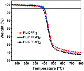 | ||
| Fig. 1 TGA curves of compounds Flu(DPP)2, Flu(DPPsF)2 and Flu(DPPdF)2 at a heating rate of 10 °C min−1 under a nitrogen flow. | ||
Theoretical calculations
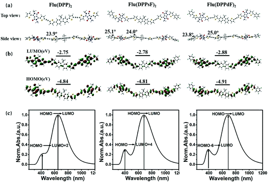
In order to evaluate the ground state geometry, the electron density distribution, the molecular energy levels and the optical absorption properties of Flu(DPP)2, Flu(DPPsF)2 and Flu(DPPdF)2, DFT and TD-DFT calculations were performed using Gaussian09 using the Becke's three-parameter gradient corrected functional (B3LYP) with a polarized 6-31G (d) basis.51 The longer alkyl chains of the compounds are replaced by methyl to simplify the calculations. The calculation results are shown in Fig. 2. The calculated data of DFT and TD-DFT are shown in Table 1. and the ESI.†| Compound | UV-Vis absorption | Cyclic voltammetry | DFT calculation | |||||
|---|---|---|---|---|---|---|---|---|
| λ solmax (nm)/ε (105 M−1 cm−1) | λ filmmax (nm) | λ filmedge (nm) | E optg (eV) | HOMOCV/LUMOCV (eV) | E CVg (eV) | HOMODFT/LUMODFT (eV) | E DFTg (eV) | |
| Flu(DPP)2 | 584/1.40 | 615 | 687 | 1.80 | −5.29/−3.43 | 1.86 | −4.84/−2.75 | 2.09 |
| Flu(DPPsF)2 | 614/0.56 | 667 | 738 | 1.68 | −5.23/−3.45 | 1.78 | −4.81/−2.78 | 2.03 |
| Flu(DPPdF)2 | 614/1.00 | 674 | 746 | 1.66 | −5.28/−3.53 | 1.75 | −4.91/−2.88 | 2.03 |
As shown in Fig. 2(a), the dihedral angles of D-π fragments for Flu(DPP)2, Flu(DPPsF)2, and Flu(DPPdF)2 are 23.9°, 24.0°, and 25.0°, respectively. The A–A′ units of Flu(DPPsF)2 and Flu(DPPdF)2 maintain good planarity with dihedral angles of 25.1° and 23.8°. The appropriate angle can avoid excessive intermolecular stacking, which is more conducive to intramolecular charge transfer (ICT).52Flu(DPPsF)2 and Flu(DPPdF)2 containing terminal fluorine-substituted phenyl groups are expected to prolong molecular conjugation and enhance the electron-withdrawing ability of terminal groups, resulting in a narrower band gap. The electronic-density distributions and energy levels are shown in Fig. 2(b). The density of the electron cloud of the HOMO is almost distributed in the whole molecule, while the electron cloud density of the lowest unoccupied molecular orbital (LUMO) is more intensive in the DPP and terminal groups with a strong electron-withdrawing ability. Compared with Flu(DPP)2, Flu(DPPsF)2 has a slightly higher HOMO and lower LUMO energy levels, thus reducing the band gap from 2.09 eV to 2.03 eV. The HOMO and LUMO energy levels of Flu(DPPdF)2 are lower than those of Flu(DPPsF)2, which is attributed to the stronger electron-withdrawing capacity of difluoro-substitution than monofluoro-substitution. In addition, the lower HOMO energy level of Flu(DPPdF)2 may lead to an increase of VOC.
The simulated absorption spectra in chloroform solution and the electronic transition of three molecules are shown in Fig. 2(c). The three molecules exhibit two main absorption bands, one of which belongs to the low-energy region mainly caused by the electronic transition from the HOMO to LUMO, and the other one is located in the high-energy region, which is caused by the electronic transition from the HOMO to LUMO+2 of Flu(DPP)2, HOMO to LUMO+4 of Flu(DPPsF)2 and the HOMO−6 to LUMO of Flu(DPPdF)2, respectively. Therefore, it is speculated from the theoretical calculation that the absorption spectra of the three compounds cover the UV-vis and near-infrared region, which indicates that they can show excellent spectral characteristics.
Spectral characteristics
The UV-Vis absorption spectra of the three molecules in chloroform solution and in the thin film state are shown in Fig. 3, and the relevant data are described in Table 1.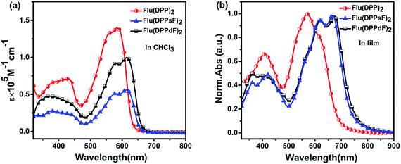 | ||
| Fig. 3 Spectral characteristics of three compounds: (a) UV-Vis absorption spectra in CHCl3 solution and (b) normalized UV-Vis absorption spectra in the thin film state. | ||
In solution, the molar extinction coefficients (ε) of Flu(DPP)2, Flu(DPPsF)2, and Flu(DPPdF)2 at the strongest absorption bands are 1.40 × 10⁵ M−1 cm−1, 0.56 × 10⁵ M−1 cm−1, and 1.00 × 10⁵ M−1 cm−1, respectively. Compared with Flu(DPP)2, the maximum absorption peaks (λsolmax) of Flu(DPPsF)2 and Flu(DPPdF)2 are red-shifted by 30 nm, indicating that the introduction of a fluorine-substituted phenyl group is helpful for capturing more photons. Furthermore, the ε of Flu(DPPdF)2 is much higher than that of Flu(DPPsF)2, indicating that the strategy of difluoro-substitution is helpful in enhancing the absorption of the material.
In the thin film state, the absorption range of three molecules shows an obvious red-shift than in solution, indicating the existence of strong π–π stacking in the solid state.31,53 According to the equation Eoptg = 1240/λedge,3 the optical band gap (Eoptg) of Flu(DPP)2, Flu(DPPsF)2 and Flu(DPPdF)2 are 1.80 eV, 1.68 eV, and 1.66 eV, respectively. Compared with Flu(DPP)2, the optical band gaps of Flu(DPPsF)2 and Flu(DPPdF)2 are narrower, which meets the narrow band gap design of organic small molecule donor materials and helps to improve the JSC of the device.54
In order to confirm the aggregation properties of three molecules, temperature-dependent absorption spectra of Flu(DPP)2, Flu(DPPsF)2 and Flu(DPPdF)2 in dichlorobenzene solutions was obtained, as shown in Fig. 4. When the solution temperature rises from 30 to 80 °C, the ratio of IA0–1/IA0−0 for three molecules gradually decreases, indicating that the strong intramolecular aggregation exists in the three molecules. Moreover, the A0–1 maximum intensities of Flu(DPP)2, Flu(DPPsF)2 and Flu(DPPdF)2 showed a certain blue-shift. As a result, the ratio of IA0–1/IA0–0 combined with the observed blue-shift suggests that rising temperature leads to molecular disorder and weakens the π–π stacking interactions. However, the shoulder peaks of Flu(DPPsF)2 and Flu(DPPdF)2 are more prominent than that of Flu(DPP)2, which indicates fluorine substituted Flu(DPPsF)2 and Flu(DPPdF)2 can form a stronger and more stable intramolecular aggregation.55,56
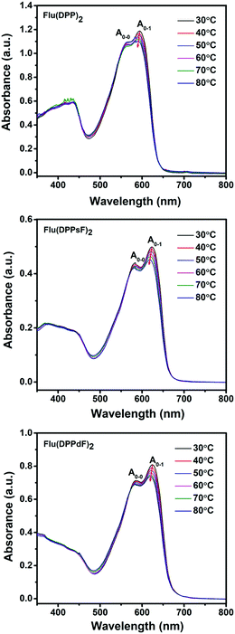 | ||
| Fig. 4 Temperature-dependent absorption spectra of Flu(DPP)2, Flu(DPPsF)2 and Flu(DPPdF)2 in dilute o-dichlorobenzene solutions. | ||
XRD analysis
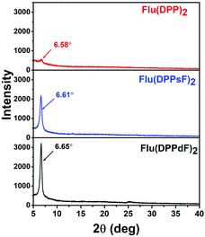
The crystallization characteristics of these SMDs were further studied by X-ray diffraction (XRD). The XRD patterns in the thin films of Flu(DPP)2, Flu(DPPsF)2 and Flu(DPPdF)2 are shown in Fig. 5, the diffraction peaks of Flu(DPP)2, Flu(DPPsF)2 and Flu(DPPdF)2 are located at 6.58° 6.61° and 6.65°, respectively, indicating three molecules possess good crystallinity.57 Compared with Flu(DPP)2, the diffraction peaks of Flu(DPPsF)2 and Flu(DPPdF)2 are stronger and sharper, indicating that the crystallinity of Flu(DPPsF)2 and Flu(DPPdF)2 is better. According to Bragg equation (2d![[thin space (1/6-em)]](https://www.rsc.org/images/entities/char_2009.gif) sin
sin![[thin space (1/6-em)]](https://www.rsc.org/images/entities/char_2009.gif) θ = nλ), the interplanar spacings of Flu(DPP)2, Flu(DPPsF)2 and Flu(DPPdF)2 are 13.52 Å, 13.38 Å and 13.29 Å, respectively. The decrease of the spacing indicates that the end-group fluorination can enhance the molecular π–π stacking.55 The XRD results are in accordance with charge mobility and photovoltaic properties of these SMDs.58
θ = nλ), the interplanar spacings of Flu(DPP)2, Flu(DPPsF)2 and Flu(DPPdF)2 are 13.52 Å, 13.38 Å and 13.29 Å, respectively. The decrease of the spacing indicates that the end-group fluorination can enhance the molecular π–π stacking.55 The XRD results are in accordance with charge mobility and photovoltaic properties of these SMDs.58
Electrochemical properties
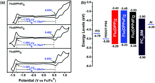
Cyclic voltammetry (CV) measurements were performed in order to investigate the electrochemical properties of three compounds. The relevant curves and data are shown in Fig. 6(a) and Table 1. The measured onset reduction potentials and oxidation potentials were −1.32 V/0.54 V, −1.30 V/0.48 V and −1.22 V/0.53 V for Flu(DPP)2, Flu(DPPsF)2 and Flu(DPPdF)2, respectively. According to the following empirical equations:47–49 HOMOCV/LUMOCV = −[EOX/red − Eferrocene1/2 + 4.8] eV, where Eferrocene1/2 = 0.05 eV the calculated HOMO and LUMO energy levels from the oxidation and reduction potentials are −5.29 eV/−3.43 eV for Flu(DPP)2, −5.23 eV/−3.45 eV for Flu(DPPsF)2, −5.28 eV/−3.53 eV for Flu(DPPdF)2. In addition, the band gaps of Flu(DPPsF)2 and Flu(DPPdF)2 are narrower than that of Flu(DPP)2, which is consistent with the trend given in the previous theoretical calculation.27 Compared with Flu(DPPsF)2, the lower HOMO level of Flu(DPPdF)2 helps to obtain higher VOC in OPV devices,59 which is due to the stronger electron-withdrawing characteristics caused by terminal difluoro-substitution. In short, the variation trends of energy levels and band gaps of the three molecules obtained from CV experiments and theoretical calculations are basically consistent, indicating that theoretical calculations can provide important information for molecular design.As shown in Fig. 6(b), the HOMO and LUMO energy levels of three molecules as donor materials match well with PC61BM, and the LUMO energy level difference with PC61BM exceeds 0.3 eV, which provides sufficient driving force for charge separation at the interface.60 The results show that the three molecules meet the requirements of photovoltaic materials as donors, which provides conditions for the preliminary study of photovoltaic devices.
Photovoltaic properties
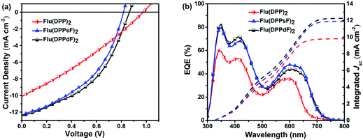
Solution-processed BHJ devices composed of ITO/PEDOT:PSS/SMDs:PC61BM/Al were prepared to evaluate the photovoltaic characteristics of new materials. The J–V curves and related photoelectric parameters are summarized in Fig. 7(a) and Table 2. Without any optimization, the PCEs of devices based on Flu(DPP)2, Flu(DPPsF)2, and Flu(DPPdF)2 reached 2.90%, 4.39% and 4.74% respectively. Compared with Flu(DPP)2-based devices, the PCEs of the devices based on Flu(DPPsF)2, and Flu(DPPdF)2 increased by 51.4% and 63.4%, respectively, mainly due to the increase of JSC and FF. In addition, compared with the Flu(DPPsF)2-based device with a VOC of 0.81 V, Flu(DPPdF)2-based devices show a higher VOC of 0.86 V, which indicates that the design of difluoro-substituted materials is better.3 In short, these results prove the rationality of molecular design strategy.| Organic active layer of devices | V OC (V) | J SC (mA cm−2) | J calSC (mA cm−2) | FF (%) | PCE (PCEave) (%) | μ h (cm2 V−1 s−1) | μ e (cm2 V−1 s−1) | μ h/μe |
|---|---|---|---|---|---|---|---|---|
| The average data of PCE are obtained from 24 devices. | ||||||||
| Flu(DPP)2:PC61BM | 0.97 | 10.13 | 9.83 | 29.51 | 2.90 (2.67) | 3.17 × 10⁻⁵ | 1.65 × 10⁻⁵ | 1.92 |
| Flu(DPPsF)2:PC61BM | 0.81 | 12.39 | 11.91 | 43.74 | 4.39 (4.08) | 7.26 × 10⁻⁵ | 6.08 × 10⁻⁵ | 1.19 |
| Flu(DPPdF)2:PC61BM | 0.86 | 12.41 | 12.28 | 44.41 | 4.74 (4.33) | 1.40 × 10⁻⁴ | 1.60 × 10⁻⁴ | 0.88 |
External quantum efficiency
The external quantum efficiency (EQE) curves of devices based on different active layer materials are shown in Fig. 7(b). All devices based on three molecules exhibit two characteristic photon-to-electron response bands, ranging from 300 nm to 750 nm. It is worth noting that in the short wavelength region (300–500 nm), the device based on Flu(DPPdF)2 has a maximum EQE value of 82.7%, while in the long wavelength region (500–750 nm), the device based on Flu(DPPsF)2 shows a maximum EQE value of 47.8%. Obviously, the devices based on Flu(DPPsF)2 and Flu(DPPdF)2 show a broader and stronger photon–electron response than devices based on Flu(DPP)2. The integrated current (JcalSC) of devices based on Flu(DPP)2, Flu(DPPsF)2, and Flu(DPPdF)2 obtained from EQE curves are 9.83 mA cm−2, 11.91 mA cm−2 and 12.28 mA cm−2, respectively, which are basically consistent with the JSC obtained by J–V measurements (error less than 5%). Based on the above analysis, it can be concluded that the devices based on Flu(DPPsF)2 and Flu(DPPdF)2 show more effective photon-to-electron response than the devices based on Flu(DPP)2. Therefore, the molecular design of extending the conjugated structure and fluorine-substitution is successful.Charge carrier transport
In order to further understand the difference in the photovoltaic performance of devices based on three materials Flu(DPP)2, Flu(DPPsF)2, and Flu(DPPdF)2, the charge carrier mobility was tested by the space charge limited current (SCLC) method. Hole mobility (μh) and electron mobility (μe) were measured with the device architectures of ITO/PEDOT:PSS/organic active layer/Au and ITO/ZnO/organic active layer/Al, respectively. The charge carrier mobility, J–V curves and the related data are shown in Fig. 8 and Table 2. As a result, the μh values of the device based on Flu(DPP)2, Flu(DPPsF)2, and Flu(DPPdF)2 are 3.17 × 10⁻⁵, 7.26 × 10⁻⁵ and 1.40 × 10⁻⁴ cm2 V−1 s−1, the corresponding μe values are 1.65 × 10⁻⁵, 6.08 × 10⁻⁵ and 1.60 × 10⁻⁴ cm2 V−1 s−1 respectively. The devices based on Flu(DPPsF)2 and Flu(DPPdF)2 show a higher hole mobility and electron mobility than devices based on Flu(DPP)2. In particular, the device based on Flu(DPPdF)2 shows the highest carrier mobility values. The ratios of μh/μe of devices based on Flu(DPP)2, Flu(DPPsF)2, and Flu(DPPdF)2 are 1.92, 1.19 and 0.88 respectively. The higher short-circuit Jsc and PCEs of devices based on Flu(DPPdF)2 benefit from its higher and more balanced μh/μe value.24,61 In addition, the contact angle of Flu(DPPdF)2 is most similar to those of PC61BM (Fig. S11 in the ESI†), indicating that there is the most appropriate miscibility between Flu(DPPdF)2 and PC61BM, which could be helpful for the formation of excellent bulk heterojunction (BHJ) morphology.57,62Conclusions
In conclusion, three new small molecule donors have been designed and synthesized successfully. In particular, two novel A′–A–π–D–π–A–A′ extended small-molecules Flu(DPPsF)2 and Flu(DPPdF)2 were constructed by introducing monofluoro and difluoro substituted phenyl groups at the end group of Flu(DPP)2. The synergistic effect of extended conjugation and end-group fluorination on photovoltaic properties were investigated comprehensively. It is worth mentioning that devices based on Flu(DPPsF)2 and Flu(DPPdF)2 achieved a higher PCE of 4.39% and 4.74%, respectively, compared with Flu(DPP)2. This is mainly because these two extended fluorine-substituted materials based on Flu(DPPsF)2 and Flu(DPPdF)2 exhibit broader light absorption, narrower band gap and better crystallinity. Moreover, the devices based on these two materials show more effective photon–electron response, higher and more balanced carrier transport characteristics. This work shows that the synergistic strategy with A′–A–π–D–π–A–A′ extended molecular and fluorine-substitution provides crucial guidance for the design of novel materials with improved photovoltaic performance.Conflicts of interest
There are no conflicts to declare.Acknowledgements
To the authors thank the support of the National Natural Science Foundation of China (No. 21102013) and the Scientific Research Foundation Project of Central Universities (DUT16ZD205).Notes and references
- H. Chen, D. Hu, Q. Yang, J. Gao, J. Fu, K. Yang, H. He, S. Chen, Z. Kan, T. Duan, C. Yang, J. Ouyang, Z. Xiao, K. Sun and S. Lu, Joule, 2019, 3, 3034–3047 CrossRef CAS.
- R. Sun, Y. Wu, X. Yang, Y. Gao, Z. Chen, K. Li, J. Qiao, T. Wang, J. Guo, C. Liu, X. Hao, H. Zhu and J. Min, Adv. Mater., 2022, 2110147 CrossRef CAS PubMed.
- X. He, L. Yin and Y. Li, New J. Chem., 2019, 43, 6577–6586 RSC.
- Z. Zheng, J. Wang, P. Bi, J. Ren, Y. Wang, Y. Yang, X. Liu, S. Zhang and J. Hou, Joule, 2022, 6, 171–184 CrossRef CAS.
- X. He, L. Yin and Y. Li, J. Mater. Chem. C, 2019, 7, 2487–2521 RSC.
- K. Wang, Y. Li and Y. Li, Macromol. Rapid Commun., 2020, 41, 1900437 CrossRef CAS PubMed.
- Y. Liu, B. Liu, C. Q. Ma, F. Huang, G. Feng, H. Chen, J. Hou, L. Yan, Q. Wei, Q. Luo, Q. Bao, W. Ma, W. Liu, W. Li, X. Wan, X. Hu, Y. Han, Y. Li, Y. Zhou, Y. Zou, Y. Chen, Y. Li, Y. Chen, Z. Tang, Z. Hu, Z. G. Zhang and Z. Bo, Sci. China: Chem., 2022, 65, 224–268 CrossRef CAS.
- T. Xu, J. Lv, K. Yang, Y. He, Q. Yang, H. Chen, Q. Chen, Z. Liao, Z. Kan, T. Duan, K. Sun, J. Ouyang and S. Lu, Energy Environ. Sci., 2021, 14, 5366–5376 RSC.
- B. Kan, Y. Kan, L. Zuo, X. Shi and K. Gao, InfoMat, 2021, 3, 175–200 CrossRef CAS.
- X. Zhang, L. Qin, Y. Li, J. Yu, H. Chen, X. Gu, Y. Wei, X. Lu, F. Gao, H. Huang, X. Zhang, L. Qin, H. Chen, X. Gu, Y. Wei, H. Huang, Y. Li, X. Lu, J. Yu and F. Gao, Adv. Funct. Mater., 2022, 2112433 CrossRef CAS.
- B. Yadagiri, K. Narayanaswamy, S. Revoju, B. Eliasson, G. D. Sharma and S. P. Singh, J. Mater. Chem. C, 2019, 7, 709–717 RSC.
- X. X. Dai, H. L. Feng, Z. S. Huang, M. J. Wang, L. Wang, D. Bin Kuang, H. Meier and D. Cao, Dyes Pigm., 2015, 114, 47–54 CrossRef CAS.
- R. Abbel, A. P. H. J. Schenning and E. W. Meijer, J. Polym. Sci., Part A: Polym. Chem., 2009, 47, 4215–4233 CrossRef CAS.
- J. U. Wallace and S. H. Chen, Adv. Polym. Sci., 2008, 212, 145–186 CAS.
- W. Ni, M. Li, B. Kan, Y. Zuo, Q. Zhang, G. Long, H. Feng, X. Wan and Y. Chen, Org. Electron., 2014, 15, 2285–2294 CrossRef CAS.
- I. Ljubić and A. Sabljić, J. Phys. Chem. A, 2011, 115, 4840–4850 CrossRef PubMed.
- K. Ramki, N. Venkatesh, G. Sathiyan, R. Thangamuthu and P. Sakthivel, Org. Electron., 2019, 73, 182–204 CrossRef CAS.
- C. Hu, L. Yin, B. Xie and Y. Li, Dyes Pigm., 2020, 183, 108709 CrossRef CAS.
- F. Bureš, RSC Adv., 2014, 4, 58826–58851 RSC.
- Y. Patil, R. Misra, F. C. Chen, M. L. Keshtov and G. D. Sharma, RSC Adv., 2016, 6, 99685–99694 RSC.
- V. Malytskyi, J. J. Simon, L. Patrone and J. M. Raimundo, RSC Adv., 2015, 5, 354–357 RSC.
- Y. Patil and R. Misra, J. Mater. Chem. C, 2019, 7, 13020–13031 RSC.
- H. Shi, Z. Gu, X. Gu, H. Pan, J. Pan, X. Hu, C. Fan, M. Shi and H. Chen, Synth. Met., 2014, 188, 66–71 CrossRef CAS.
- W. Lee, J. Choi and J. W. Jung, Dyes Pigm., 2019, 161, 283–287 CrossRef CAS.
- C. B. Nielsen, M. Turbiez and I. McCulloch, Adv. Mater., 2013, 25, 1859–1880 CrossRef CAS PubMed.
- B. Sun, W. Hong, Z. Yan, H. Aziz and Y. Li, Adv. Mater., 2014, 26, 2636–2642 CrossRef CAS PubMed.
- F. Cheng, X. He, L. Yin, B. Xie and Y. Li, Dyes Pigm., 2020, 176, 108211 CrossRef CAS.
- W. Li, W. S. C. Roelofs, M. M. Wienk and R. A. J. Janssen, J. Am. Chem. Soc., 2012, 134, 13787–13795 CrossRef CAS PubMed.
- D. Molina, M. J. Álvaro-Martins and Á. Sastre-Santos, J. Mater. Chem. C, 2021, 9, 16078–16109 RSC.
- J. Wu, Q. Liu, L. Ye, X. Guo, Q. Fan, J. Lv, M. Zhang and W. Y. Wong, Energy Fuels, 2021, 35, 19061–19068 CrossRef CAS.
- B. Xie, L. Yin, J. Fan, C. Liu and Y. Li, J. Mater. Chem. C, 2022, 10, 3248–3258 RSC.
- B. Jia, S. Dai, Z. Ke, C. Yan, W. Ma and X. Zhan, Chem. Mater., 2018, 30, 239–245 CrossRef CAS.
- B. Zhao, W. Wang, Z. Cong, L. Wang, H. Wu, S. Liu and C. Gao, ACS Appl. Energy Mater., 2021, 4, 4119–4128 CrossRef CAS.
- L. Wang, L. Yin, C. Ji, Y. Zhang, H. Gao and Y. Li, Org. Electron., 2014, 15, 1138–1148 CrossRef CAS.
- Z. Jia, S. Qin, L. Meng, Q. Ma, I. Angunawela, J. Zhang, X. Li, Y. He, W. Lai, N. Li, H. Ade, C. J. Brabec and Y. Li, Nat. Commun., 2021, 12, 1–10 CrossRef PubMed.
- F. Cheng, X. He, L. Yin, B. Xie and Y. Li, Dyes Pigm., 2020, 176, 108211 CrossRef CAS.
- J. Pan, Y. Shi, J. Yu, H. Zhang, Y. Liu, J. Zhang, F. Gao, X. Yu, K. Lu and Z. Wei, ACS Appl. Mater. Interfaces, 2021, 13, 22531–22539 CrossRef CAS PubMed.
- W. Zhao, S. Li, H. Yao, S. Zhang, Y. Zhang, B. Yang and J. Hou, J. Am. Chem. Soc., 2017, 139, 7148–7151 CrossRef CAS PubMed.
- Abdullah, S. Ameen, M. S. Akhtar, L. Fijahi, E. B. Kim and H. S. Shin, Opt. Mater., 2019, 91, 425–432 CrossRef CAS.
- Suman, A. Bagui, A. Garg, B. Tyagi, V. Gupta and S. P. Singh, Chem. Commun., 2018, 54, 4001–4004 RSC.
- M. Li, G. Zhang, L. Xiong, M. Zhu, Y. Pei, Q. Peng and Y. Liu, Dyes Pigm., 2018, 158, 402–411 CrossRef CAS.
- N. Qiu, C. Liu, H. Lang, J. Xu, R. Su, J. Jiang, J. Tian and J. Li, New J. Chem., 2022, 46, 8500–8506 RSC.
- Q. Wu, D. Deng, J. Zhang, W. Zou, Y. Yang, Z. Wang, H. Li, R. Zhou, K. Lu and Z. Wei, Sci. China: Chem., 2019, 62, 837–844 CrossRef CAS.
- D. Fan, C. Fan, H. Fan, S. Bao, Y. Zheng, H. Yang, X. Zhu, C. Cui and Y. Li, Mol. Syst. Des. Eng., 2021, 6, 739–747 RSC.
- P. Blom, M. de Jong and M. van Munster, Phys. Rev. B: Condens. Matter Mater. Phys., 1997, 55, R656 CrossRef CAS.
- K. Shi, B. Qiu, C. Zhu, J. Yao, X. Xia, J. Zhang, L. Meng, S. Huang, X. Lu, Y. Wan, Z. G. Zhang and Y. Li, ACS Appl. Mater. Interfaces, 2021, 13, 54237–54245 CrossRef CAS PubMed.
- H. Gao, Y. Li, L. Wang, C. Ji, Y. Wang, W. Tian, X. Yang and L. Yin, Chem. Commun., 2014, 50, 10251–10254 RSC.
- C. Ji, L. Yin, L. Wang, T. Jia, S. Meng, Y. Sun and Y. Li, J. Mater. Chem. C, 2014, 2, 4019–4026 RSC.
- Z. Li, Y. Zhang, A. L. Holt, B. P. Kolasa, J. G. Wehner, A. Hampp, G. C. Bazan, T.-Q. Nguyen and D. E. Morse, New J. Chem., 2011, 35, 1327–1334 RSC.
- S. Kawasaki, J. Ujita, K. Toyota and M. Yoshifuji, Chem. Lett., 2005, 34, 724–725 CrossRef CAS.
- L. Wang, L. Yin, L. Wang, B. Xie, C. Ji and Y. Li, Dyes Pigm., 2017, 140, 203–211 CrossRef CAS.
- Jiali Song, Xiaonan Xue, Bingbing Fan, Lijun Huo and Yanming Sun, Mater. Chem. Front., 2018, 2, 1626–1630 RSC.
- C. Ye, Y. Wang, Z. Bi, X. Guo, Q. Fan, J. Chen, X. Ou, W. Ma and M. Zhang, Org. Electron., 2018, 53, 273–279 CrossRef CAS.
- D. Meng, R. Zheng, Y. Zhao, E. Zhang, L. Dou and Y. Yang, Adv. Mater., 2022, 34, 2107330 CrossRef CAS PubMed.
- M. Li, Z. Qiu, G. Zhang, Y. Liu, L. Xiong, D. Bai, M. Zhu, Q. Peng and W. Zhu, J. Mater. Chem. A, 2018, 6, 12493–12505 RSC.
- Z. Qiu, X. Xu, L. Yang, Y. Pei, M. Zhu, Q. Peng and Y. Liu, Sol. Energy, 2018, 161, 138–147 CrossRef CAS.
- M. Li, S. Wang, C. Bao, Z. Liu, D. Bai, Z. Yang, W. Zhu, Q. Peng and Y. Liu, J. Mater. Chem. C, 2019, 7, 12217–12230 RSC.
- Z. Qiu, X. Xu, S. Zhang, P. Wang, Y. Wang, Y. Pei, Q. Peng and Y. Liu, Dyes Pigm., 2017, 147, 505–513 CrossRef CAS.
- Q. Fan, Z. Xu, X. Guo, X. Meng, W. Li, W. Su, X. Ou, W. Ma, M. Zhang and Y. Li, Nano Energy, 2017, 40, 20–26 CrossRef CAS.
- T. Xu, J. Lv, K. Yang, Y. He, Q. Yang, H. Chen, Q. Chen, Z. Liao, Z. Kan, T. Duan, K. Sun, J. Ouyang and S. Lu, Energy Environ. Sci., 2021, 14, 5366–5376 RSC.
- Y. Un Kim, G. Eun Park, S. Choi, D. Hee Lee, M. Ju Cho and D. H. Choi, J. Mater. Chem. C, 2017, 5, 7182–7190 RSC.
- Y. Wang, S. Dong, Y. Miao, D. Li, W. Qin, H. Cao, L. Yang, L. Li and S. Yin, IEEE J. Photovoltaics, 2017, 7, 550–557 Search PubMed.
Footnote |
| † Electronic supplementary information (ESI) available: Synthesis, 1H NMR, 13C NMR spectra, HRMS, computational electronic transitions, and CV curve of Fc/Fc+. See DOI: https://doi.org/10.1039/d2ma00510g |
| This journal is © The Royal Society of Chemistry 2022 |

