 Open Access Article
A facile structural strategy for a wearable strain sensor based on carbon nanotube modified helical yarns†
Wei
Zhao‡
 *abd and
Sheng
Xu‡
ac
aSchool of Chemical and Material Engineering, Jiangnan University, Wuxi, Jiangsu Province 214122, P. R. China. E-mail: zwchouvie@163.com
bDepartment of Mechanical Engineering, University of Delaware, Newark, Delaware 19716, USA
cSchool of Textiles and Clothing, Jiangnan University, Wuxi, Jiangsu Province 214122, P. R. China
dXin Feng Ming Group Co., Ltd, Tongxiang, Zhejiang Province 314500, P. R. China
First published on 25th November 2021
Abstract
Wearable sensors have gained considerable popularity due to the potential feasibility in flexible electronics. In this work, a facile fabrication strategy for a wearable strain sensor is presented based on a hierarchical-gap response mechanism. A double-helical-structured elastic string was employed as the stretchable substrate, and carbon nanotubes were chosen as the resistance-sensitive nanostructures. A CNT-modified elastic string (CES) was obtained by directly coating CNTs onto the substrate. After polydimethylsiloxane encapsulation, a fiber-shaped resistive-type strain sensor was fabricated. It was attached to different joints for human body motion monitoring. The double-helical structure could produce hierarchical gaps as the applied strain increased, which served as spatial complements to allow a well-connected structure to be formed. The CES sensor could accurately capture different levels of strain caused by physiological signals and joint motions. This facile fabrication strategy is expected to be used to produce large-scale strain sensors with ultra-sensitivity.
Introduction
Wearable strain sensors have gained considerable popularity due to the development of flexible electronics over the past decade.1–3 By using these sensors, precise information about human movements can be obtained in real time and online.4,5 To date, various types of strain sensors have been used, such as resistive,6 amperometric,7 capacitive,8 optical,9 and field-effect sensors.10 In terms of simple fabrication and data output, resistive sensors exhibit excellent performances, and they are cost effective and universally available.11,12 They can sensitively monitor human body movements, including muscle motions, joint motions, and even motions due to breathing or the human pulse.13,14Considerable efforts have been made to develop new materials to achieve resistive-type strain sensors. The general strategy is to incorporate conducting metallic components (e.g., Au nanoparticles, Ag nanofibers, or metallic oxides) or carbon nanomaterials (e.g., carbon black, carbon nanofibers, graphene, or carbon nanotubes) into dielectric elastomeric matrices (e.g., silicone, rubber, and soft polymers).15–17 Such sensors work by simply monitoring electrical resistance changes in response to their deformations.18 Therefore, elastomeric matrices should be compliant with various degrees of movements to achieve high sensitivity. To this end, numerous novel geometric structures of matrices have been designed, such as fish-scale-like microstructures,19 percolation networks,20 crack-sensed mechanosensors,21 and sandwich construction.22 Although these micro-structured sensors have exhibited good sensing performances, their complicated preparation procedures have restricted their development in large-scale fabrication.
Recently, various innovative materials have been used as strain sensors, such as cotton thread,23 tissue paper,24 chewing gum,25 plasticine,26 and rubber bands.27 These materials have attracted growing interest due to their stable structures and widely available sources, as well as their sustainability, low cost, and eco-friendliness. Through direct spinning or dipping, conductive nanomaterials can be anchored onto these flexible substrates to form a resistance-sensitive layer, which demonstrates great power to fabricate wearable devices. However, it remains a great challenge to fabricate flexible strain sensors with reliable performance using a large-scale approach.
Herein, a fast and simple fabrication strategy for a wearable strain sensor is proposed based on a double-helical structured substrate. Carbon nanotubes (CNTs), chosen as the resistance-sensitive nanostructure, were directly coated onto the substrate to form a CNT-modified elastic string (CES). A fiber-shaped strain sensor was fabricated after polydimethylsiloxane (PDMS) encapsulation, which provided a stretchable and recoverable path for responding to tensile strain stimuli. Under the applied strain, hierarchical gaps were produced as spatial complements to form a well-connected structure with excellent compactness. Based on these hierarchical gaps, the CES sensor could capture different levels of human movements. Thus, the focus of this study is on the hierarchical-structured synergy effect of the double-helical CES fiber on improving strain sensitivity. Also, low-cost and easy preparation enable this strategy as a powerful candidate to produce ultra-sensitive strain sensors on a large scale.
Experimental
Preparation of the CNT modified elastic string (CES)
The CNT aqueous dispersion with a mass concentration of 5 wt% (SIZICYL XCR2G 100728) was supplied by Nanocyl SA Co. (Belgium). The dispersion was first treated ultrasonically for 1 h. The spring-structured elastic string was obtained from Greenbrier International, Inc (Canada), which was used as the fibrous sensor substrate. It consisted of an elastic rubber core and helical polypropylene (PP) yarns tightly wound around the core to form a spring-like structure. The elastic string substrate (d = 0.8 mm) was cut into pieces with a uniform length of 5 cm. A piece of the substrate was cleaned with deionized water, and dried for 30 min at 50 °C. Then it was coated with the CNT dispersion solution, resulting in the formation of a CNT modified elastic string (CES) (Fig. 1a). Subsequently, the CES fiber was air-dried for 30 min.Motion sensor fabrication
The as-prepared CES fiber was encapsulated with PDMS to form a resistance sensing element. The PDMS base and curing agent (Sylgard®184, Dow Corning) were mixed uniformly at a mass ratio of 10![[thin space (1/6-em)]](https://www.rsc.org/images/entities/char_2009.gif) :
:![[thin space (1/6-em)]](https://www.rsc.org/images/entities/char_2009.gif) 1.28 After the degassing procedure, the liquid mixture was brushed evenly onto the surface of the CES fiber. Then it was thermally cured at 120 °C for 2 h to form a PDMS encapsulation layer. Finally, two copper foil electrodes were attached on both ends of the CES fiber to fabricate the CES sensor, as illustrated in Fig. 1a.
1.28 After the degassing procedure, the liquid mixture was brushed evenly onto the surface of the CES fiber. Then it was thermally cured at 120 °C for 2 h to form a PDMS encapsulation layer. Finally, two copper foil electrodes were attached on both ends of the CES fiber to fabricate the CES sensor, as illustrated in Fig. 1a.
Characterization
The morphologies of the elastic string substrate and the CES fiber were imaged by using a LEICA M165 C optical microscope and a SEM/FIB Auriga 60 scanning electron microscope. The electrical resistance responses of the CES sensor were measured as a function of time using an Agilent 34411A digital multimeter. To assess the response characteristics of the sensor on different parts of the human body, it was attached to skin (e.g., finger, wrist, neck, and knee) and connected with the digital multimeter by using electrical wires. The electrical resistance variations were recorded in real time as the motion occurred.
Results and discussion
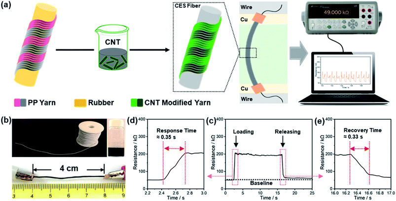
The fabrication of the CES fiber is schematically depicted in Fig. 1a. To obtain the CES, the spring-structured elastic string was coated with CNTs. After the modification, the pristine white elastic string became black (Fig. 1b). The length of the CES fiber was approximately 4 cm after it was assembled with copper electrodes. The preliminary experiments were performed to assess the electrical resistance response of the CES fiber. As shown in Fig. 1c, upon the application of an axial tensile strain of unknown magnitude at a relatively fast speed, a sensitive resistance increase could be detected. The resistance reached a stable level in approximately 0.35 s (Fig. 1d). When the strain was removed, the resistance recovered in 0.33 s (Fig. 1e). The response time and recovery time are directly related to the rate of strain application. These results confirmed the applicability of CES fibers as strain sensors with rapid responses to external strains.To further confirm the adsorption of CNTs onto the elastic substrate, optical microscopic examination was conducted before and after CNT adsorption. Fig. 2a shows a pristine substrate with a visible helical appearance. It consisted of two side-by-side spiral PP yarns wound onto an elastic rubber core with a double-helical structure. One of the yarns was extracted and stretched as shown in Fig. 2b, where the spiral PP filaments are clearly seen. This relatively loose and porous surface structure facilitated the penetration of the conductive CNTs into the inter-yarn and inter-filament gaps, resulting in an electrically conductive network. Fig. 2c shows the black surface appearance of the CES fiber where the spiral pattern was well maintained.
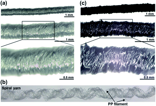 | ||
| Fig. 2 Optical microscopic images of (a) pristine elastic string substrate, (b) CES fiber, and (c) an isolated and stretched spiral yarn of the elastic string substrate. | ||
To further investigate the composition and construction of the CES fiber, scanning electron microscopy (SEM) images were obtained, as shown in Fig. 3 and S1.† There were numerous PP filaments intertwined in the pristine substrate (Fig. 3a and S1a†). The diameter of the filament was approximately 20 μm. Many gaps were present between filaments, which could act as containers to hold CNT reserves. Due to these gaps, the CNTs could permeate and anchor onto the yarns. As shown in Fig. 3b and S1b,† on the surface of the CES fiber, the CNT stacking layer was uniform. Each filament was well coated, and the filaments maintained their original helical structure after CNT modification. In this modification layer, the CNTs crisscrossed one another to form a compact interconnected network (Fig. 3c and d). To retain the CNT network, a PMDS encapsulation layer was synthesized because of its outstanding elasticity with stable chemical and mechanical properties. After the encapsulation procedure, the helical structure was maintained (Fig. S2†). These compositions were important to maintain a well-connected conductive network and resistance responses. Finally, the two ends of the CES fiber were attached to Cu foil electrodes for electrical measurements.
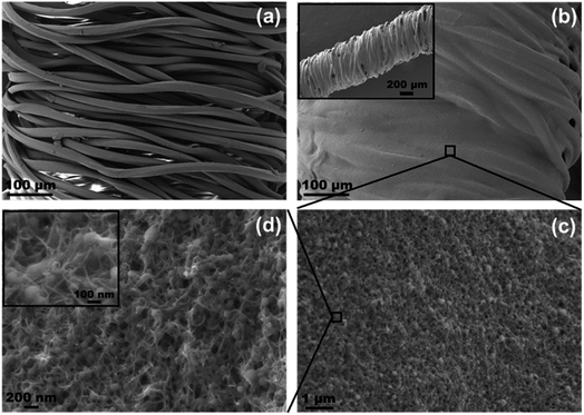 | ||
| Fig. 3 SEM images of (a) pristine elastic string substrate and (b) CES fiber. (c) and (d) are enlarged views of (b) and (c), respectively. | ||
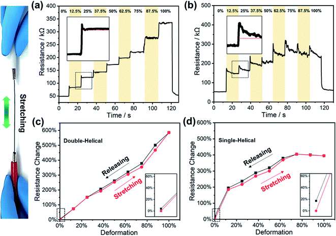
To demonstrate the relative effectiveness of the helical structure in sensing performance, two substrates with different geometric constructions (single-helical and double-helical) were selected for comparison. The single-helical substrate consisted of one spiral yarn wound onto the elastic core. After following the same preparation procedure, two different sensors were obtained. The spring-shaped PP filaments and the elastic rubber core gave the necessary flexibility and stretchability to the sensors. The CNTs coated on the substrate provided a percolated network for conducting electricity, and its electric resistance changed when the sensor was stretched. Fig. 4a and b show the electric resistance changes with a step-wise increment in sensor tensile deformation for the double-helical and single-helical sensor, respectively. The initial electric resistance (Ri) mainly consisted of two parts, the intrinsic resistance of the CNTs (R0) and the contact resistance of the entangled CNTs (Rc). Because R0 changed negligibly, the variation in resistance (ΔR) was predominant due to ΔRc. As shown in Fig. 4a, with the step-wise increase in the tensile strain, there was a corresponding increase in ΔR of the CES fiber. The relative resistance change in a continuous stretching/releasing process is shown in Fig. 4c. The stretching and releasing paths in the resistance change were almost identical. After releasing the load, the initial resistance Ri was nearly recovered (inset of Fig. 4c), which revealed that there was no evident response-hysteresis. On the other hand, in the case of the single-helical sensor (Fig. 4b), the resistance also increased with the step-wise increment in the tensile strain with a relatively-long equilibrium time, resulting in different resistance curve shapes of the double-helical and single-helical CES sensors. However, Fig. 4d shows that there was an evident residual resistance change after complete release of the applied strain. Therefore, the sensing performance of the double-helical CES sensor was superior to that of the single-helical sensor.
In order to better understand the influence of the helical-structures on sensing performance, the microstructural changes due to axial loading were examined, as shown in Fig. 5. Under the tensile strain, the helical yarns were stretched. As the strain increased, the gap between the neighboring portions of the helical yarn enlarged gradually. For the single-helical sensor (Fig. 5a), the PP yarn was stretched significantly, and the rubber core was exposed. Different level gaps worked simultaneously: the primary gap I provided grooves that acted as containers for CNT reserves, and the secondary gap II produced larger structural changes for the strain response. On the contrary, for the double-helical CES, two yarns were densely arranged side-by-side to maintain a compact structure invariably (Fig. 5b). Compared to the single-helical fiber, the double-helical construction could enhance the compactness of the conductive structure, and thus, stable conductive paths were achieved during stretching process. In addition to gaps I and II that were similar to those of the single-helical sensor, there was a tertiary alternate gap in the same yarn of the CES, denoted as gap III. These hierarchical gaps served as spatial complements, maintaining a well-connected construction as the applied strain increased. As a result, the resistance change of the double-helical sensor was relatively smaller than that of the single-helical one, but the resistance response was more stable than that of the single-helical one. Based on this hierarchical-gap synergy effect, the CES could produce multifarious structural changes that enabled it to capture wide-level strains.
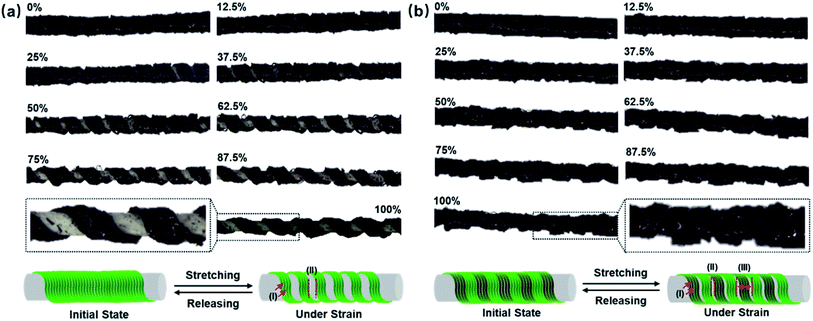 | ||
| Fig. 5 Optical microscopic images of (a) single-helical sensor and (b) double-helical CES sensor under progressive tensile strain. | ||
The strain response behaviors of the CES sensors with different CNT loadings were also investigated (Fig. S3†). With the increase in the CNT content, Ri of the sensors decreased. For the CES with low a CNT loading (Fig. S3a†), the maximum strain of the resistance variation was limited due to the limits of the electrical performance. The strain response range increased with the increase of CNTs. However, with the high CNT content, the performance of the sensor degraded (Fig. S3c†). This was due to an elastic hysteresis of the sensor with an excessive CNT content. Therefore, an optimized CNT content was confirmed as shown in Fig. S3† to prepare an optimal CES sensor. Here, the CES prepared with 2 times coating was chosen as the optimal sensor to investigate its performance.
For a practical strain sensor, stability is a crucial factor. Herein, PDMS was used not only to hold CNT reserves, but also to improve the stability. The resistance responses of the CES were recorded under 12.5% repetitive strains (Fig. S4a†). During this process, the sensor still retained stable responses. For a sensor without PDMS, there was an evident increase in resistance during the stretching (Fig. S4b†). This was mainly due to the encapsulation of flexible PDMS to provide a protective effect. Additionally, the stretched helical structure could slide back to its initial position intact after strain release, and thus, it exhibited recovery stability. The Ri of ten individually prepared sensors was compared to investigate the reproducibility (Fig. S5†), which was determined to be satisfactory. These observations indicated that the CES has potential for use as a stable and reliable sensing device.
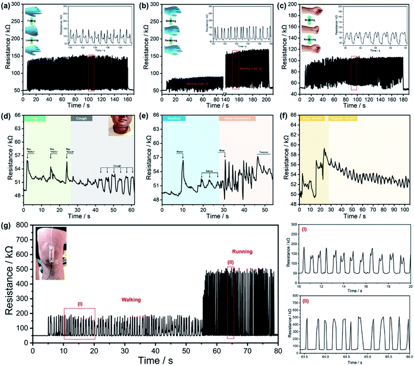
To demonstrate the feasibility of responding to the external mechanical stimuli, the CES was mounted at different locations to capture the human motions. First, real-time hand movements were monitored with repeated bending (Fig. 6a–c). For every bending motion, a resistance increase occurred immediately. When the tested finger or hand returned to the original position, the increased resistance immediately recovered to its original value. Additionally, the CES sensor was able to detect physiological signals. It was attached to a human neck, and four motion modes (talking, coughing, swallowing, and head movement) were executed. As demonstrated in Fig. 6d and e, rapid and sensitive resistance responses were tracked. Different levels of breathing were also detected by the CES as shown in Fig. 6f. It exhibited a stable response curve for successive regular breathing, indicating that the CES sensor exhibited ultra-sensitivity for subtle human motions. In addition to detecting small amplitude movements, monitoring strenuous exercise was also critical for assessing the practicality. By mounting the CES sensor on the kneecap, measurements were performed for walking and running. In this process, the resistance-time waveform exhibited a periodic and well-defined response (Fig. 6g), which demonstrated that the sensor was ideal for various applications in dynamic motion sensing. During the experimentations, the volunteer was tested repeatedly, and sweat was produced. Small amounts of sweat were found to have little effect on the sensing performance, mainly due to the encapsulation effect of PDMS.
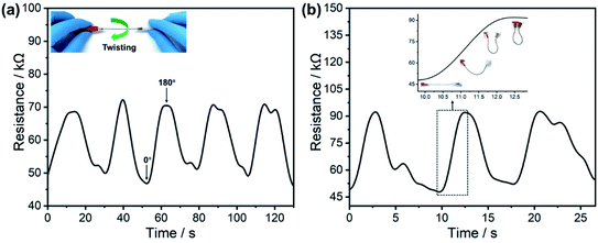
From the above results, it can be speculated that in addition to tensile deformation, the CES was also sensitive to torsion and bending stimuli. The CES was subjected to a reciprocating torsion from 0° to 180°, and the corresponding resistance variation was recorded as shown in Fig. 7a. Torsion led to a significant change in the resistance. The same result was obtained in the bending process (Fig. 7b). As the curvature increased, the resistance of the CES increased. Hence, the CES sensor could sense not only stretching but also torsion and bending.
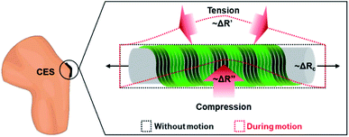
A comprehensive response process can be proposed depending on the above-tested results (Fig. 8). During the body movements, the CES experienced tension and compression stimuli. Three types of resistance changes, ΔRc, ΔR′ and ΔR′′, occurred in different deformation regions. ΔRc corresponded to the deformation along the tensile direction. ΔR′ was a result of intense tensile stress on the high strain side, and ΔR′′ was related to the compression portion. Accordingly, the total ΔR during movements is the synergistic combination, which can be denoted as ΔR = ΔRc + ΔR′ + ΔR′′. The abovementioned results highlighted the practical applications of the CES as a sensitive wearable device for the monitoring of human joint motions and physiological signals. This sensor has potential for use in more complex scenarios where multiple sensors are applied to simultaneously collect diverse information about the human body.
Conclusion
In summary, a facile and low-cost fabrication method for a fiber-shaped strain sensor was developed based on a CNT-modified elastic string (CES). A double-helical structured elastic substrate combined with conductive CNTs was used to prepare a resistance-sensitive composite fiber. After PDMS encapsulation, a resistive-type strain sensor was fabricated to detect human body motions. The double-helical CES produced hierarchical gaps which served as spatial complements to keep the structure compact. Based on this hierarchical-gap synergy effect, the sensor exhibited rapid and stable responses to different human motions with ultra-sensitivity. Due to its low cost, and large scale and simple fabrication process, this sensor has potential for use in wearable electronics, especially for monitoring of human joint motions and physiological signals.Conflicts of interest
There are no conflicts to declare.Acknowledgements
Wei Zhao is very grateful to Prof. Tsu-Wei Chou, Department of Mechanical Engineering, University of Delaware, for his contribution to this work. The authors would like to thank Overseas Research Program for Graduate Students of Jiangnan University and China Postdoctoral Science Foundation (2021M691363).References
- S. Lim, D. Son, J. Kim, Y. B. Lee, J. K. Song, S. Choi, D. J. Lee, J. H. Kim, M. Lee, T. Hyeon and D. H. Kim, Adv. Funct. Mater., 2015, 25, 375–383 CrossRef CAS.
- Y. C. Lai, J. A. Deng, S. L. Zhang, S. M. Niu, H. Y. Guo and Z. L. Wang, Adv. Funct. Mater., 2017, 27, 1604462 CrossRef.
- J. W. Zhong, Y. Ma, Y. Song, Q. Z. Zhong, Y. Chu, I. Karakurt, D. B. Bogy and L. W. Lin, ACS Nano, 2019, 13, 7107–7116 CrossRef CAS PubMed.
- G. F. Cai, J. X. Wang, K. Qian, J. W. Chen, S. H. Li and P. S. Lee, Adv. Sci., 2017, 4, 1600190–1600197 CrossRef PubMed.
- K. Dong, J. A. Deng, W. B. Ding, A. C. Wang, P. H. Wang, C. Y. Cheng, Y. C. Wang, L. M. Jin, B. H. Gu, B. Z. Sun and Z. L. Wang, Adv. Energy Mater., 2018, 8, 1801114–1801126 CrossRef.
- L. J. Pan, A. Chortos, G. H. Yu, Y. Q. Wang, S. Isaacson, R. Allen, Y. Shi, R. Dauskardt and Z. N. Bao, Nat. Commun., 2014, 5, 3002–3010 CrossRef PubMed.
- W. Gao, S. Emaminejad, H. Y. Y. Nyein, S. Challa, K. Chen, A. Peck, H. M. Fahad, H. Ota, H. Shiraki, D. Kiriya, D. H. Lien, G. A. Brooks, R. W. Davis and A. Javey, Nature, 2016, 529, 509–514 CrossRef CAS.
- A. Frutiger, J. T. Muth, D. M. Vogt, Y. Mengüç, A. Campo, A. D. Valentine, C. J. Walsh and J. A. Lewis, Adv. Mater., 2015, 27, 2440–2446 CrossRef CAS PubMed.
- D. Z. Stupar, J. S. Bajic, L. M. Manojlovic, M. P. Slankamenac, A. V. Joza and M. B. Zivanov, IEEE Sensor. J., 2012, 12, 3424–3431 Search PubMed.
- O. Y. Kweon, M. Y. Lee, T. Park, H. Jang, A. Jeong, M. K. Um and J. H. Oh, J. Mater. Chem. C, 2019, 7, 1525–1531 RSC.
- X. Liao, Z. Zhang, Z. Kang, F. F. Gao, Q. L. Liao and Y. Zhang, Mater. Horiz., 2017, 4, 502–510 RSC.
- Y. L. Wang, J. Hao, Z. Q. Huang, G. Q. Zheng, K. Dai, C. T. Liu and C. Y. Shen, Carbon, 2018, 126, 360–371 CrossRef CAS.
- Y. Wang, L. Wang, T. T. Yang, X. Li, X. B. Zang, M. Zhu, K. L. Wang, D. H. Wu and H. W. Zhu, Adv. Funct. Mater., 2014, 24, 4666–4670 CrossRef CAS.
- S. Ryu, P. Lee, J. B. Chou, R. Z. Xu, R. Zhao, A. J. Hart and S. G. Kim, ACS Nano, 2015, 9, 5929–5936 CrossRef CAS PubMed.
- M. Amjadi, A. Pichitpajongkit, S. Lee, S. Ryu and I. Park, ACS Nano, 2014, 8, 5154–5163 CrossRef CAS PubMed.
- M. Amjadi, K. U. Kyung, I. Park and M. Sitti, Adv. Funct. Mater., 2016, 26, 1678–1698 CrossRef CAS.
- Z. Lou, L. L. Wang and G. Z. Shen, Adv. Mater. Technol., 2018, 3, 1800444–1800461 CrossRef.
- T. Yamada, Y. Hayamizu, Y. Yamamoto, Y. Yomogida, A. Izadi-Najafabadi, D. N. Futaba and K. Hata, Nat. Nanotechnol., 2011, 6, 296–301 CrossRef CAS.
- Q. Liu, J. Chen, Y. Li and G. Shi, ACS Nano, 2016, 10, 7901–7906 CrossRef CAS PubMed.
- K. K. Kim, S. Hong, H. M. Cho, J. Lee, Y. D. Suh, J. Ham and S. H. Ko, Nano Lett., 2015, 15, 5240–5247 CrossRef CAS PubMed.
- D. Kang, P. V. Pikhitsa, Y. W. Choi, C. Lee, S. S. Shin, L. F. Piao, B. Park, K. Y. Suh, T. Kim and M. Choi, Nature, 2014, 516, 222–226 CrossRef CAS PubMed.
- L. Lu, X. Wei, Y. Zhang, G. Zheng, K. Dai, C. Liu and C. Shen, J. Mater. Chem. C, 2017, 5, 7035–7042 RSC.
- Y. Q. Li, Y. A. Samad and K. Liao, J. Mater. Chem. A, 2015, 3, 2181–2187 RSC.
- Y. Q. Li, Y. A. Samad, T. Taha, G. W. Cai, S. Y. Fu and K. Liao, ACS Sustainable Chem. Eng., 2016, 4, 4288–4295 CrossRef CAS.
- M. A. Darabi, A. Khosrozadeh, Q. Wang and M. Xing, ACS Appl. Mater. Interfaces, 2015, 7, 26195–26205 CrossRef CAS PubMed.
- C. S. Boland, U. Khan, G. Ryan, S. Barwich, R. Charifou, A. Harvey, C. Backes, Z. L. Li, M. S. Ferreira, M. E. Möbius, R. J. Young and J. N. Coleman, Science, 2016, 354, 1257–1260 CrossRef CAS PubMed.
- C. S. Boland, U. Khan, C. Backes, A. O'Neill, J. McCauley, S. Duane, R. Shanker, Y. Liu, I. Jurewicz, A. B. Dalton and J. N. Coleman, ACS Nano, 2014, 8, 8819–8830 CrossRef CAS.
- H. S. Liu, B. C. Pan and G. S. Liou, Nanoscale, 2017, 9, 2633–2639 RSC.
Footnotes |
| † Electronic supplementary information (ESI) available. See DOI: 10.1039/d1na00215e |
| ‡ W. Z. and S. X. contributed equally to this work. |
| This journal is © The Royal Society of Chemistry 2022 |

