 Open Access Article
Creative Commons Attribution 3.0 Unported Licence
Single-walled carbon nanotubes as a reducing agent for the synthesis of a Prussian blue-based composite: a quartz crystal microbalance study†
Yosuke
Ishii
 *,
Ayar
Al-zubaidi
 *,
Yoshimitsu
Taniguchi
,
Shinya
Jindo
and
Shinji
Kawasaki
 *
*
Department of Life Science and Applied Chemistry, Nagoya Institute of Technology, Gokiso-cho, Showa-ku, Nagoya 466-8555, Japan. E-mail: a.al-zubaidi.052@nitech.jp; ishii.yosuke@nitech.ac.jp; kawasaki.shinji@nitech.ac.jp
First published on 24th November 2021
Abstract
We investigated the synthesis mechanism of Prussian blue (PB) crystals supported on single-walled carbon nanotubes (SWCNTs), by performing in situ quartz crystal microbalance (QCM) measurements to probe the change in the electrode mass during the reaction, and using photoirradiation at designated stages of the process. We found that in contrast to existing hypotheses, light irradiation played no role in the synthesis process of Prussian blue on SWCNTs. On the other hand, the number of electrons transferred per one mole of the obtained product, and the number of electrons transferrable from SWCNTs, calculated from the density of states (DOS) of the SWCNTs in the sample, both favor the hypothesis of the reaction being triggered by direct electron transfer from SWCNTs to Fe3+, which occurs because of the energy difference between the Fermi level of SWCNTs and redox potential of Fe3+ ions.
Introduction
The market for lithium ion batteries continues to expand beyond portable electronics and electric/hybrid vehicles, requiring the device performance to sometimes accommodate a range of extreme temperatures spanning from −40 to 70 °C and wider.1–3 In particular, the use of lithium ion batteries in cold climates, space missions, military and other low temperature applications emphasizes the need to improve the performance of lithium ion batteries at sub-zero temperatures, at which the charging capability of the system drops considerably due to multiple possible factors, including most notably the deterioration in the lithium ion diffusion kinetics at low temperature.4,5 This problem sparked research efforts aiming to design electrode and electrolyte materials capable of delivering consistently high performance in wide temperature ranges, by modifying a number of existing battery materials or exploring new materials for the purpose.6–9Among the materials being investigated towards that end are the class of cyano-based coordination materials called Prussian blue analogues (PBAs). Prussian blue is an iron centred mixed-valence coordination compound with the formula Fe4(III)[Fe(II)(CN)6]3·nH2O (n = 14–16), in which the Fe(III) atom is coordinated to nitrogen and the Fe(II) atom is coordinated to carbon in a basic face-centred cubic lattice structure.10–12 Prussian blue is an archetypical compound after which the family of PBAs is modelled with the general formula AxT[M(CN)6]·nH2O, in which A is an alkaline ion, T is a high-spin transition metal that coordinates with the N atoms, and M is a low-spin transition metal that coordinates with the C atoms.13,14 BPAs are attractive as both cathode and anode materials for alkaline ion-based batteries because their cage-like framework is suitable for reversible ion intercalation and maintains high structural integrity during cycling. They have been the focus of considerable research that demonstrated their promising energy and power performance at room temperature.15–19
The synthesis of PB is often a relatively easy and scalable one-pot process that mainly proceeds hydrothermally, by precipitation, or by electrodeposition.13,20–23 Among the three methods, precipitation is the most scalable and energy efficient, as it normally proceeds rapidly upon adding the metal ion salt to a solution of the cyanide ion salt precursor. The rapid reaction however hinders the product controllability and results in large random-morphology PB particles or aggregations with poor rate capability and cycling performance in energy applications. This issue can be overcome by adding coordination agents to reduce the reaction rate and allow the control of the product morphology, or by nucleating PB on the surface of a host material to ensure the formation of smaller well-distributed particles.13 The host material itself may contribute to improving the performance of the electrode. This is especially true for nanocarbon materials like graphene24–27 and carbon nanotubes28–32 that have been reported to impart high electric conductivity, nanoscale porosity, and a controllable surface structure and chemistry to the performance equation. Also importantly and in the context of low-temperature energy storage, the nucleation of PB on carbon nanotubes has been shown to result in a composite electrode that enjoys superior low-temperature power performance in a sodium ion battery, because carbon nanotubes provided a high active surface area for the electrode on the electrolyte side, and an excellent conductive path for electrons between the solid phase and the current collector.28
The role of nanocarbons has also been hypothesized by some studies to go beyond that of the conductive particle carrier that optimizes the PB particle size and electrode surface area. The synthesis reaction of PB on nanocarbons has been proposed to proceed by the carbon materials themself33,34 or the functional entities on their surface35 acting as a reducing agent by providing the electrons needed for the reaction to proceed. This hypothesis is difficult to confirm when graphene or multiwalled carbon nanotubes (MWCNTs) are used30,36,37 because the possibility and direction of electron transfer depend on the electronic structure of the material and the value of its Fermi level energy in relation to the redox potential of the synthesis reaction. This relation is difficult to map with graphene, a zero-band gap material that normally includes a number of chemical groups on its surface, or MWCNTs that are composed of a number of concentric tubes and overlapping electronic states. In addition, the crystallinity of the wall of any type of carbon nanotube is compromised, and its chemical composition is modified with functional groups that form on the surface when the sample goes through purification or functionalization,29–33,37–39 which adds another layer of complexity to the task of elucidating the synthesis mechanism.
In this study, we investigated the synthesis mechanism of PB on single-walled carbon nanotubes (SWCNTs) with high crystallinity and a narrow diameter range, and hence a relatively well defined electronic density of states (DOS). Experimentally, we probed the synthesis process using quartz crystal microbalance (QCM) measurements to track the change in the electrode mass resulting from the formation of PB particles on the surface of SWCNTs, and used light irradiation at designated stages of the synthesis process to test the hypothesis of spontaneous charge transfer versus the mechanism of photo-induced charge transfer proposed in some studies.24,40,41 The role of SWCNTs as an electron donor was also verified experimentally through the choice of the precursor material. The precipitation of PB is a solution reaction of either ferric chloride (FeCl3) with ferrocyanide ions [Fe(II)(CN)6]4−, or ferrous chloride (FeCl2) with ferricyanide [Fe(III)(CN)6]3− ions.13 Should carbon nanotubes provide the electrons necessary for reducing Fe3+ and seeding Fe2+ ions on the surface of the tubes, the precursor combination of choice will be FeCl3 with [Fe(III)(CN)6]3−.
To evaluate the performance of the composite at low temperature, the prepared composite was used as a cathode for a lithium ion battery charged and discharged at temperatures as low as −60 °C, and its energy storage behaviour was compared to crystalline PB and LiCoO2 that is commonly used as a lithium ion battery cathode.
Experimental
The composite was synthesized using ferric chloride FeCl3 and potassium ferricyanide K3[Fe(CN)6] as PB precursors and single-walled carbon nanotubes (SWCNTs) produced using the eDips method,42 with an estimated mean diameter of 2.5 nm and carbon content of over 90% as supplied by the manufacturer. The electrolyte used in the electrochemical measurements was prepared by dissolving 1.0 M lithium bis(trifluoromethanesulfonyl)imide (LiTFSI) in the organic solvent 2-methyltetrahydrofuran (2-methyl THF). Table S1† gives the manufacturer information for all the materials used in the present study.All the materials were used as received without further purification, except for the SWCNT sample that went through a purification treatment to remove any amorphous carbon and metallic catalyst particles on the surface of the tubes, an annealing treatment to improve the crystallinity of the tubes and cover any defects on their walls, and then a decapping treatment to open the end caps of the tubes.43–45
To synthesize the composite, first the SWCNT sample was dispersed in distilled water using a BRANSON SONIFIER 250 probe sonicator, and then 50 mL of a mixture containing 1.0 mM of FeCl3 and 1.0 mM of K3[Fe(CN)6] was added to the dispersion. The reaction mixture was left for 15 hours, and then the solid precipitate formed at the end of the reaction was collected and dried at 65 °C for 24 hours to obtain the composite that will be referred to as SWCNT@PB.
The structure of the composite was characterized along with a reference sample of crystalline PB. X-ray diffraction (XRD) measurements were performed using a Rigaku MINIFLEX diffractometer with a Cu Kα X-ray source (wavelength λ = 1.54 Å). The average tube diameter in the bare SWCNT sample and the SWCNT@PB sample was determined by simulating the XRD peaks of SWCNTs, and the obtained diameter values were used to determine candidate chiralities for the tubes in the sample, and obtain their DOS profiles using the Kataura plot.46
The composition of SWCNT@PB was determined from thermogravimetric analysis (TGA) using a SHIMADZU TGA-50 analyser operated at a heating rate of 5 °C min−1 under an air flow. Scanning electron microscopy (SEM) imaging and energy dispersive X-ray analysis (EDS) of the samples were performed using a JEOL JSM-7800F high resolution electric field emission scanning electron microscope. Transmission electron microscopy (TEM) imaging was performed using a JEOL JEM-z2500 transmission electron microscope. The sample to be probed was prepared by dispersing 1.0 mg in 5.0 mL ethanol using an AS ONE VS-70RS1 ultrasonic cleaner, and then depositing one drop of the dispersion on a STEM Cu150P copper microgrid and allowing it to dry at room temperature.
To prepare the SWCNT electrode for QCM measurements, the sample was first dispersed in N-methyl-2-pyrrolidone (NMP) using a BRANSON SONIFIER 250 ultrasonic probe, to obtain a solution 0.5 mg mL−1 in concentration. The solution was drop-cast onto a gold-coated quartz crystal and then left on a hot plate at 120 °C to dry. The QCM tracking of the SWCNT@PB synthesis took place in a dark room and as follows: first distilled water was drop-cast on the quartz substrate supporting the SWCNTs, and the frequency of the QCM was left to stabilize. The PB precursor solution was then added drop-wise, and the mass change was measured. After 10 minutes of adding the precursor solution, it was light-irradiated for 15 minutes to test the hypothesis of photo-induced synthesis. The solution was then monitored for 15 hours to allow the system sufficient time for stabilization. The change in the electrode mass was calculated from the change in resonance frequency using Sauerbrey's equation:
 | (1) |
The SWCNT@PB composite was used as a cathode material for a lithium ion battery to evaluate its low-temperature performance in comparison to that of crystalline PB and LiCoO2. The SWCNT@PB sample assumed the form of a free-standing paper, and was therefore used as an electrode without any binding or conductive additives. When crystalline PB or LiCoO2 was used, the electrode was prepared by mixing the active material (AC) with polyvinylidene fluoride (PVDF) as a binder and acetylene black (AB) as a conductive agent with an AC![[thin space (1/6-em)]](https://www.rsc.org/images/entities/char_2009.gif) :
:![[thin space (1/6-em)]](https://www.rsc.org/images/entities/char_2009.gif) AB
AB![[thin space (1/6-em)]](https://www.rsc.org/images/entities/char_2009.gif) :
:![[thin space (1/6-em)]](https://www.rsc.org/images/entities/char_2009.gif) PVDF ratio of 4
PVDF ratio of 4![[thin space (1/6-em)]](https://www.rsc.org/images/entities/char_2009.gif) :
:![[thin space (1/6-em)]](https://www.rsc.org/images/entities/char_2009.gif) 4
4![[thin space (1/6-em)]](https://www.rsc.org/images/entities/char_2009.gif) :
:![[thin space (1/6-em)]](https://www.rsc.org/images/entities/char_2009.gif) 2 for PB and 6
2 for PB and 6![[thin space (1/6-em)]](https://www.rsc.org/images/entities/char_2009.gif) :
:![[thin space (1/6-em)]](https://www.rsc.org/images/entities/char_2009.gif) 2
2![[thin space (1/6-em)]](https://www.rsc.org/images/entities/char_2009.gif) :
:![[thin space (1/6-em)]](https://www.rsc.org/images/entities/char_2009.gif) 2 for LiCoO2, and then spreading the obtained paste onto an aluminum current collector sheet, and drying at 120 °C for a minimum of 1 hour under vacuum. The obtained electrode was used as the half-cell working electrode against lithium metal as the counter electrode, with 1.0 M LiTFSI/2-methyl THF organic solution as the electrolyte.
2 for LiCoO2, and then spreading the obtained paste onto an aluminum current collector sheet, and drying at 120 °C for a minimum of 1 hour under vacuum. The obtained electrode was used as the half-cell working electrode against lithium metal as the counter electrode, with 1.0 M LiTFSI/2-methyl THF organic solution as the electrolyte.
Constant current charge/discharge measurements were performed at room temperature and sub-zero temperatures using a TOSCAT-3200 (Toyo System) galvanostat. The voltage range was 2.3–3.3 V for PB and SWCNT@PB, and 3.0–4.0 V for LiCoO2. The room temperature measurements were performed in an argon-filled glove box, and the low temperature measurements were performed after assembling the half cell in an argon-filled atmosphere and then placing it inside a constant-temperature chamber (Espec SU-241) to perform the measurements. The device was charged and discharged at a current density of 25 mA g−1 relative to the mass of the active material in the working electrode (LiCoO2, crystalline PB, or PB in the SWCNT@PB composite). The charge/discharge capacity was calculated from the equation:
 | (2) |
 | (3) |
Results and discussion
The nucleation of PB on the surface of SWCNTs results in a coating of small-size PB particles distributed on the surface of SWCNT bundles, which improves the charge storage efficiency of PB electrodes in energy devices. The morphology of the composite is seen in the SEM images in Fig. 1. Compared to the bare SWCNTs in Fig. 1a, the bundles of SWCNT@PB in Fig. 1b are covered with a layer of PB particles, as can be inferred from the bamboo segment-like deposits with smaller particle size compared to crystalline PB (Fig. 1c), and the bundle size that is larger than that of the bare SWCNTs. The EDS elemental analysis of SWCNT@PB (Fig. 1d) shows the characteristic peaks for Fe and N atoms in the sample.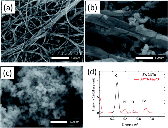 | ||
| Fig. 1 SEM images for pure SWCNTs (a), SWCNT@PB (b), and crystalline PB (c), and EDS analysis for SWCNTs and SWCNT@PB (d). | ||
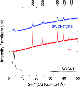
The characterization of the samples using X-ray diffraction (XRD) measurements resulted in the diffraction patterns shown in Fig. 2. The diffraction patterns for SWCNT@PB had similar peak positions to those of the crystalline PB sample, confirming the similarity in the structure. The 200 distance (the Fe–Fe distance) was calculated using Bragg's equation:
2d200![[thin space (1/6-em)]](https://www.rsc.org/images/entities/char_2009.gif) sin sin![[thin space (1/6-em)]](https://www.rsc.org/images/entities/char_2009.gif) θ = nλ θ = nλ | (4) |
The 200 interplanar distance for the crystalline PB was 5.12 Å, versus 5.09 Å for SWCNT@PB.
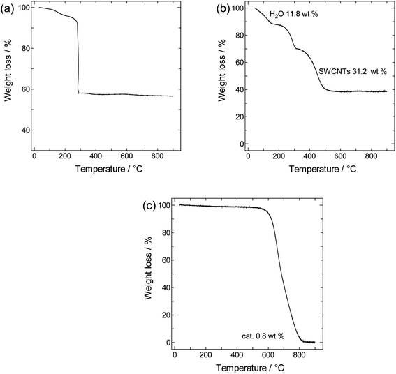
TGA curves obtained for crystalline PB, SWCNTs, and SWCNT@PB are shown in Fig. 3. Both crystalline PB (Fig. 3a) and SWCNT@PB (Fig. 3b) go through mass loss around 100 °C that is associated with the loss of zeolitic water, and around 260 °C, which is likely the combination of the loss of coordinated water and the decomposition of BP.47,48 Additional combustion stages are seen at 450 °C for SWCNT@PB, versus 580 °C for the annealed SWCNTs (Fig. 3c), both due to the decomposition of SWCNTs. After subtracting the SWCNT mass content (31.2%) and residual catalyst content (0.8%) and then normalizing the percentages to mass of the dry sample (calculated after the removal of H2O of 11.8%), a PB content of 63.7% in the composite was obtained, equivalent to a PB![[thin space (1/6-em)]](https://www.rsc.org/images/entities/char_2009.gif) :
:![[thin space (1/6-em)]](https://www.rsc.org/images/entities/char_2009.gif) SWCNT mass ratio of 1.8
SWCNT mass ratio of 1.8![[thin space (1/6-em)]](https://www.rsc.org/images/entities/char_2009.gif) :
:![[thin space (1/6-em)]](https://www.rsc.org/images/entities/char_2009.gif) 1.
1.
TEM images show a bundle of bare SWCNTs 50 nm to 100 nm in size in Fig. 4a, versus a core–shell-structured composite in Fig. 4b, in which a PB layer 20–50 nm in thickness is deposited on the surface of a SWCNT bundle around 100 nm in size. The TEM images did not show epitaxy in the growth of PB on the SWCNT bundles. We hypothesize that the difficulty in achieving epitaxial growth is caused by the fact that PB particles coat the bundles of SWCNTs, not the individual tubes, which should reduce the possibility of epitaxy due to intra-bundle heterogeneity in the diameters and chiralities of individual SWCNTs. In addition, the bamboo-like segments observed in the SEM images suggest simultaneous multi-site nucleation and poly-crystal formation rather the seamless single crystal expected in epitaxial growth. Nonetheless, the possibility of a seamless growth of a single crystal-like PB on SWCNTs remains an open question and an interesting one, especially in light of recent studies that reported the successful epitaxial growth of a number of crystalline materials on the surface of SWCNTs.49,50
 | ||
| Fig. 4 TEM images of (a) bare SWCNTs and (b) SWCNT@PB composite, and (c) core–shell model of the SWCNT@PB composite. | ||
For an independent estimation of the PB![[thin space (1/6-em)]](https://www.rsc.org/images/entities/char_2009.gif) :
:![[thin space (1/6-em)]](https://www.rsc.org/images/entities/char_2009.gif) SWCNT content ratio in the composite, we used the core–shell structural model (Fig. 4c) and size information obtained from SEM and TEM images. For a PB layer thickness of 30 nm, SWCNT bundle diameter of 100 nm, and tube length of 1 nm, the volume is 12
SWCNT content ratio in the composite, we used the core–shell structural model (Fig. 4c) and size information obtained from SEM and TEM images. For a PB layer thickness of 30 nm, SWCNT bundle diameter of 100 nm, and tube length of 1 nm, the volume is 12![[thin space (1/6-em)]](https://www.rsc.org/images/entities/char_2009.gif) 243 nm3 for PB versus 7859 nm3 for SWCNTs, resulting in a PB
243 nm3 for PB versus 7859 nm3 for SWCNTs, resulting in a PB![[thin space (1/6-em)]](https://www.rsc.org/images/entities/char_2009.gif) :
:![[thin space (1/6-em)]](https://www.rsc.org/images/entities/char_2009.gif) SWCNT volume ratio of 1.56
SWCNT volume ratio of 1.56![[thin space (1/6-em)]](https://www.rsc.org/images/entities/char_2009.gif) :
:![[thin space (1/6-em)]](https://www.rsc.org/images/entities/char_2009.gif) 1. Assuming a density of 1.80 g cm−3 for PB12 and 1.40 g cm−3 for SWCNTs,51 we obtained a PB
1. Assuming a density of 1.80 g cm−3 for PB12 and 1.40 g cm−3 for SWCNTs,51 we obtained a PB![[thin space (1/6-em)]](https://www.rsc.org/images/entities/char_2009.gif) :
:![[thin space (1/6-em)]](https://www.rsc.org/images/entities/char_2009.gif) SWCNT mass ratio of 2
SWCNT mass ratio of 2![[thin space (1/6-em)]](https://www.rsc.org/images/entities/char_2009.gif) :
:![[thin space (1/6-em)]](https://www.rsc.org/images/entities/char_2009.gif) 1, which is consistent with the ratio of 1.8
1, which is consistent with the ratio of 1.8![[thin space (1/6-em)]](https://www.rsc.org/images/entities/char_2009.gif) :
:![[thin space (1/6-em)]](https://www.rsc.org/images/entities/char_2009.gif) 1 determined from TGA measurements.
1 determined from TGA measurements.
To elucidate the synthesis mechanism and the potential role of SWCNTs in it, we performed QCM measurements to monitor the increase in the electrode mass due to the formation of PB particles, and identify the factors involved in the process. The QCM method probes the mass change through the changes it causes to the resonance frequency of the quartz crystal supporting the electrode.52,53
The in situ QCM setup and obtained results are shown in Fig. 5, where on and off in Fig. 5b denote the beginning and end of light irradiation, respectively, and the reference point (t = 0 seconds) is set as the time at which we started the addition of the PB precursor. Fig. 5b shows that the mass of the quartz crystal supporting SWCNTs increased sharply and immediately after the start of the addition of the PB precursor solution. The graph also shows that no additional change in mass occurred upon light irradiation, leading us to conclude that photo-induced charge separation does not seem to be involved in the Fe3+ reduction step of the composite synthesis. The duration for probing mass change was extended to 15 hours as seen in Fig. 5c, which shows that the system was allowed sufficient time for the precursors to react and for the material composition to stabilize. This again dismisses the possibility of later factors contributing to the product formation mechanism.
 | ||
| Fig. 5 (a) QCM experiment (b) in situ tracking of electrode mass during synthesis and (c) extended time tracking of the synthesis process. | ||
In a study by Choi et al.,54 the authors proposed the reduction of metallic Au and Pt ions to be triggered by spontaneous charge transfer from SWCNTs to the metallic ions, due to the difference between Fermi level energy for SWCNTs (0.5 V higher than the standard hydrogen electrode SHE) and the redox potential for those metals. In the case of PB, the synthesis reaction is:
| A+ + Fe(CN)63− + Fe2+ → AxFe(III)[Fe(II)(CN)6]y | (5a) |
| Fe(III)(CN)63− + Fe2+ → Fe(III)4[Fe(II)(CN)6]3 | (5b) |
When FeCl3 is used as the starting material, the reaction in eqn (5b) and the formation of PB will be dependent on and proceeded by the essential step of the reduction of Fe3+ to Fe2+:
Fe3+ + e− ![[left over right harpoons]](https://www.rsc.org/images/entities/char_21cb.gif) Fe2+; E = +0.771 V vs. SHE Fe2+; E = +0.771 V vs. SHE | (6) |
The redox potential of Fe3+ (+0.771 V vs. SHE or −5.21 V vs. vacuum) is lower than the Fermi level of SWCNTs (−4.45 V vs. vacuum),55 which means that the hypothesis of spontaneous electron transfer from SWCNTs to Fe3+ should hold true for the formation of PB in the composite, provided of course that SWCNTs can offer the required supply of electrons for the reaction. This can be judged by estimating the number of electrons needed for the synthesis reaction versus the number of electrons available for transfer from SWCNTs. The former can be determined using the PB content determined from TGA measurements, and the latter may be estimated from the electronic density of states (DOS) of SWCNTs, which will depend strongly on the SWCNT chirality56 and in consequence its diameter. The exact chirality and DOS profile are hard to identify because a sample of SWCNTs will include a mixture of tubes of different chiralities. However, the narrow diameter range in our sample limits the number of those chiralities and allows the approximation of the DOS profile using one proxy chirality.
We calculated the number of electrons transferred in the synthesis reaction from the PB![[thin space (1/6-em)]](https://www.rsc.org/images/entities/char_2009.gif) :
:![[thin space (1/6-em)]](https://www.rsc.org/images/entities/char_2009.gif) SWCNT mass ratio obtained from TGA measurements (1.8
SWCNT mass ratio obtained from TGA measurements (1.8![[thin space (1/6-em)]](https://www.rsc.org/images/entities/char_2009.gif) :
:![[thin space (1/6-em)]](https://www.rsc.org/images/entities/char_2009.gif) 1), and the number of electrons required to synthesize 1 mol of PB. An ideal defect-free PB has the formula Fe4(III)[Fe(II)(CN)6]3, with a molecular mass of 859.23 g mol−1. The PB formula contains three Fe(II) atoms, which means that according to eqn (5b) and (6), the formation of 1 mol of PB will necessitate the preliminary step of the reduction of three Fe3+ ions and hence the transfer of 3 electrons to the precursor solution.
1), and the number of electrons required to synthesize 1 mol of PB. An ideal defect-free PB has the formula Fe4(III)[Fe(II)(CN)6]3, with a molecular mass of 859.23 g mol−1. The PB formula contains three Fe(II) atoms, which means that according to eqn (5b) and (6), the formation of 1 mol of PB will necessitate the preliminary step of the reduction of three Fe3+ ions and hence the transfer of 3 electrons to the precursor solution.
Using the mass ratio obtained from TGA measurements, the total number of electrons transferred will be:
In a composite with a PB![[thin space (1/6-em)]](https://www.rsc.org/images/entities/char_2009.gif) :
:![[thin space (1/6-em)]](https://www.rsc.org/images/entities/char_2009.gif) SWCNT mass ratio of 1.8
SWCNT mass ratio of 1.8![[thin space (1/6-em)]](https://www.rsc.org/images/entities/char_2009.gif) :
:![[thin space (1/6-em)]](https://www.rsc.org/images/entities/char_2009.gif) 1, the number of moles of carbon is:
1, the number of moles of carbon is:
Therefore, the number of electrons needed per carbon atom is:
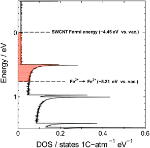
Next we estimate the number of transferrable electrons from SWCNTs. To do that we first used the Kataura plot to find candidate chiralities for SWCNTs with diameter size close to the mean diameter of our sample, and identified (21,16) semiconducting SWCNTs and (21,15) metallic SWCNTs as proxy chiralities for the calculations (DOS profiles shown in Fig. S1†). The number of transferrable electrons in SWCNTs will be that in the energy range between the Fermi level of SWCNTs (−4.45 V vs. vacuum)55 and the redox potential of Fe3+ (+0.771 V vs. SHE or −5.21 V vs. vacuum). The resulting difference of 0.76 V should promote electron transfer from SWCNTs to Fe3+ as shown in Fig. 6.
We used the trapezoidal formula to integrate the density of states over the indicated energy interval, and obtained a value of 5.0 × 10⁻² electron per carbon atom for the (21,16) semiconducting SWCNTs and 5.3 × 10⁻² electron per carbon atom for the (21,15) metallic SWCNTs. The two values are close to the value of 7.6 × 10⁻² obtained from TGA measurements, which is consistent with the hypothesis of PB formation by direct electron transfer from SWCNTs to Fe3+.
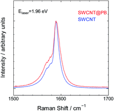
Finally, we characterized the bare SWCNTs and SWCNT@PB using Raman spectroscopy for insight into the charge carrier levels in both and the possibility of electron transfer. The Raman spectrum of SWCNTs comprises characteristic peaks that depend on the electronic structure of the SWCNTs.57,58 These peaks change in intensity, location, shape and other characteristics upon electron transfer to or from the tubes.59–66 The spectra for bare SWCNTs and SWCNT@PB are shown in Fig. 7 for the region where the double component G band is located. This peak appears due to bond stretching of all pairs of sp2 atoms in polyaromatic hydrocarbons.67 The two components of this band in SWCNTs are the G+ band around 1580–1590 cm−1 and the G− band around 1560–1570 cm−1. The spectra in our study were collected using a He–Ne laser with an energy of 1.96 eV, which is close to the value of the energy transition between the second set of van Hove singularities in the DOS profile of the (21,5) SWCNTs (also known as EM22). This causes the excitation laser to prominently probe the characteristic peaks of the metallic SWCNTs in our sample, which is seen from the lower component of the G band that appears as an asymmetric peak assuming the so-called BWF line shape characteristic of metallic SWCNTs and graphite intercalation compounds.57,68 The intensity of the peak is higher and the BWF line shape is more asymmetric for SWCNT@PB compared to that of bare SWCNTs. This indicates higher levels of charge carriers (in this case positively charged holes) in the metallic tubes in SWCNT@PB compared to the bare SWCNTs, and further supports the hypothesis of direct electron transfer from SWCNTs and their role as the reducing agent in the PB synthesis reaction.
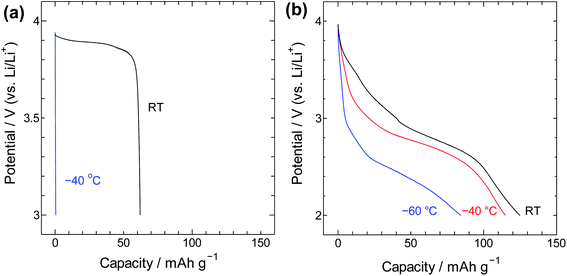
For insight into the material's energy storage behaviour, the SWCNT@PB composite was used as a cathode material in a lithium-ion battery setting to evaluate its low-temperature performance. Constant current charge/discharge measurements were performed using SWCNT@PB and for comparison, LiCoO2 that is a common cathode material for lithium ion batteries. The results are shown in Fig. 8 and show that while the common cathode fails to work at −40 °C, the SWCNT@PB composite electrode continues to charge and discharge at temperature as low as −60 °C.
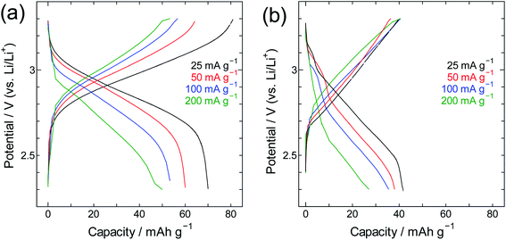
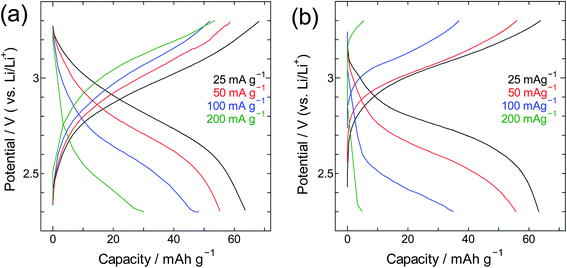
The performance of SWCNT@PB was also compared to that of crystalline PB (Fig. 9 and 10). Here one can see that for crystalline PB (Fig. 9) the slope of the charge/discharge curve increases visibly with current density at room temperature, versus minimally at −40 °C. This shows the effect of low diffusion kinetics at low temperature that results in consistently low capacity values in the whole current density range. The trend for the SWCNT@PB (Fig. 10) shows superior low-temperature performance compared to crystalline PB at low-to-moderate current density, but does not seem to cope as efficiently at higher current densities. This raises the question of the stability of the composite at high rates, and necessitates further work to optimize the synthesis conditions, product properties, and high rate performance. Nonetheless and even before optimization, the SWCNT@PB demonstrates advantage over crystalline PB and LiCoO2, performing well at temperature as low as −60 °C and maintaining a coulombic efficiency above 90% for 100 cycles (Fig. S2†).
Conclusions
The synthesis of Prussian blue on SWCNTs can proceed by direct and spontaneous electron transfer from SWCNTs to the precursor material. In situ QCM tracking of the synthesis reaction showed that the formation of PB is instantaneous upon the addition of the precursor to the solution and that photoirradiation did not seem to contribute to additional reactions in our study. The number of electrons available from the SWCNTs used in our study was shown to be sufficient for the formation of PB with the content determined using TGA measurements, and Raman spectroscopy measurements showed higher hole density on the spectrum of the SWCNTs in the composite compared to that of bare SWCNTs. The findings of our study serve as a proof of concept for SWCNT Fermi level chemistry and open the door for future synthesis processes in which SWCNTs are designed to catalyse the desired reaction.Author contributions
The manuscript was written through contributions of all authors and they have all given approval to the final version of the manuscript.Conflicts of interest
There are no conflicts to declare.Acknowledgements
This work was supported by the JSPS Kakenhi (Grant No. 19H02809, 20K20946, and 21K05258). The work was performed under the approval of the Photon Factory Program Advisory Committee (Proposal No. 2018G088, 2020G059).References
- Y. Ein-Eli, S. R. Thomas, R. Chadha, T. J. Blakley and V. R. Koch, Li-Ion Battery Electrolyte Formulated for Low-Temperature Applications, J. Electrochem. Soc., 1997, 144, 823 CrossRef CAS.
- R. Hamlen, G. Au, M. Brundage, M. Hendrickson, E. Plichta, S. Slane and J. Barbarello, US Army portable power programs, J. Power Sources, 2001, 97–98, 22–24 CrossRef CAS.
- M. C. Smart, B. V. Ratnakumar, L. D. Whitcanack, K. B. Chin, S. Surampudi, H. Croft, D. Tice and R. Staniewicz, Improved low-temperature performance of lithium-ion cells with quaternary carbonate-based electrolytes, J. Power Sources, 2003, 119–121, 349–358 CrossRef CAS.
- J. Fan and S. Tan, Studies on Charging Lithium-Ion Cells at Low Temperatures, J. Electrochem. Soc., 2006, 153, A1081 CrossRef CAS.
- J. Fan, On the discharge capability and its limiting factors of commercial 18650 Li-ion cell at low temperatures, J. Power Sources, 2003, 117, 170–178 CrossRef CAS.
- S. Tan, L. Wang, L. Bian, J. Xu, W. Ren, P. Hu and A. Chang, Highly enhanced low temperature discharge capacity of LiNi1/3Co1/3Mn1/3O2 with lithium boron oxide glass modification, J. Power Sources, 2015, 277, 139–146 CrossRef CAS.
- D. Luo, G. Li, C. Yu, L. Yang, J. Zheng, X. Guan and L. Li, Low-concentration donor-doped LiCoO2 as a high performance cathode material for Li-ion batteries to operate between −10.4 and 45.4 °C, J. Mater. Chem., 2012, 22, 22233–22241 RSC.
- L. Liao, P. Zuo, Y. Ma, Y. An, G. Yin and Y. Gao, Effects of fluoroethylene carbonate on low temperature performance of mesocarbon microbeads anode, Electrochim. Acta, 2012, 74, 260–266 CrossRef CAS.
- X.-L. Wu, Y.-G. Guo, J. Su, J.-W. Xiong, Y.-L. Zhang and L.-J. Wan, Carbon-Nanotube-Decorated Nano-LiFePO4@C Cathode Material with Superior High-Rate and Low-Temperature Performances for Lithium-Ion Batteries, Adv. Energy Mater., 2013, 3, 1155–1160 CrossRef CAS.
- J. F. Keggin and F. D. Miles, Structures and Formulæ of the Prussian Blues and Related Compounds, Nature, 1936, 137, 577–578 CrossRef CAS.
- J. F. Duncan and P. W. R. Wigley, 206. The electronic structure of the iron atoms in complex iron cyanides, J. Chem. Soc., 1963, 1120–1125 RSC.
- H. J. Buser, D. Schwarzenbach, W. Petter and A. Ludi, The crystal structure of Prussian blue: Fe4[Fe(CN)6]3 xH2O, Inorg. Chem., 1977, 16, 2704–2710 CrossRef CAS.
- W.-J. Li, C. Han, G. Cheng, S.-L. Chou, H.-K. Liu and S.-X. Dou, Chemical Properties, Structural Properties, and Energy Storage Applications of Prussian Blue Analogues, Small, 2019, 15, 1900470 CrossRef.
- Y. Matos-Peralta and M. Antuch, Review—Prussian Blue and Its Analogs as Appealing Materials for Electrochemical Sensing and Biosensing, J. Electrochem. Soc., 2019, 167, 037510 CrossRef.
- K. Hurlbutt, S. Wheeler, I. Capone and M. Pasta, Prussian Blue Analogs as Battery Materials, Joule, 2018, 2, 1950–1960 CrossRef CAS.
- J. Qian, C. Wu, Y. Cao, Z. Ma, Y. Huang, X. Ai and H. Yang, Prussian Blue Cathode Materials for Sodium-Ion Batteries and Other Ion Batteries, Adv. Energy Mater., 2018, 8, 1702619 CrossRef.
- B. Wang, Y. Han, X. Wang, N. Bahlawane, H. Pan, M. Yan and Y. Jiang, Prussian Blue Analogs for Rechargeable Batteries, iScience, 2018, 3, 110–133 CrossRef CAS PubMed.
- H. Yi, R. Qin, S. Ding, Y. Wang, S. Li, Q. Zhao and F. Pan, Structure and Properties of Prussian Blue Analogues in Energy Storage and Conversion Applications, Adv. Funct. Mater., 2021, 31, 2006970 CrossRef CAS.
- F. Wang, Y. Liu, H.-J. Wei, T.-F. Li, X.-H. Xiong, S.-Z. Wei, F.-Z. Ren and A. A. Volinsky, Recent advances and perspective in metal coordination materials-based electrode materials for potassium-ion batteries, Rare Met., 2021, 40, 448–470 CrossRef CAS.
- S. Kjeldgaard, I. Dugulan, A. Mamakhel, M. Wagemaker, B. B. Iversen and A. Bentien, Strategies for synthesis of Prussian blue analogues, R. Soc. Open Sci., 2021, 8, 201779 CrossRef CAS.
- A. Azhar, Y. Li, Z. Cai, M. B. Zakaria, M. K. Masud, M. S. A. Hossain, J. Kim, W. Zhang, J. Na, Y. Yamauchi and M. Hu, Nanoarchitectonics: A New Materials Horizon for Prussian Blue and Its Analogues, Bull. Chem. Soc. Jpn., 2019, 92, 875–904 CrossRef CAS.
- M. B. Zakaria and T. Chikyow, Recent advances in Prussian blue and Prussian blue analogues: synthesis and thermal treatments, Coord. Chem. Rev., 2017, 352, 328–345 CrossRef CAS.
- M. Gautam, K. Poudel, C. S. Yong and J. O. Kim, Prussian blue nanoparticles: synthesis, surface modification, and application in cancer treatment, Int. J. Pharm., 2018, 549, 31–49 CrossRef CAS.
- P. L. dos Santos, V. Katic, K. C. F. Toledo and J. A. Bonacin, Photochemical one-pot synthesis of reduced graphene oxide/Prussian blue nanocomposite for simultaneous electrochemical detection of ascorbic acid, dopamine, and uric acid, Sens. Actuators, B, 2018, 255, 2437–2447 CrossRef CAS.
- P. H. Trindade Soares and E. Nossol, Self-Recharging Reduced Graphene Oxide-Prussian Blue Electrodes for Transparent Batteries, ACS Appl. Nano Mater., 2019, 2, 2241–2249 CrossRef CAS.
- L. Chen, X. Wang, X. Zhang and H. Zhang, 3D porous and redox-active Prussian blue-in- graphene aerogels for highly efficient electrochemical detection of H2O2, J. Mater. Chem., 2012, 22, 22090–22096 RSC.
- H. Yang, L. Sun, J. Zhai, H. Li, Y. Zhao and H. Yu, In situ controllable synthesis of magnetic Prussian blue/graphene oxide nanocomposites for removal of radioactive cesium in water, J. Mater. Chem. A, 2014, 2, 326–332 RSC.
- Y. You, H.-R. Yao, S. Xin, Y.-X. Yin, T.-T. Zuo, C.-P. Yang, Y.-G. Guo, Y. Cui, L.-J. Wan and J. B. Goodenough, Subzero-Temperature Cathode for a Sodium-Ion Battery, Adv. Mater., 2016, 28, 7243–7248 CrossRef CAS PubMed.
- J. Zhai, Y. Zhai, D. Wen and S. Dong, Prussian Blue/Multiwalled Carbon Nanotube Hybrids: Synthesis, Assembly and Electrochemical Behavior, Electroanalysis, 2009, 21, 2207–2212 CrossRef CAS.
- S. Han, Y. Chen, R. Pang, P. Wan and M. Fan, Fabrication of Prussian Blue/Multiwalled Carbon Nanotubes/Glass Carbon Electrode through Sequential Deposition, Ind. Eng. Chem. Res., 2007, 46, 6847–6851 CrossRef CAS.
- S. Zhang, G. Wang, B. Wang, J. Wang, J. Bai and H. Wang, 3D Carbon Nanotube Network Bridged Hetero-Structured Ni-Fe-S Nanocubes toward High-Performance Lithium, Sodium, and Potassium Storage, Adv. Funct. Mater., 2020, 30, 2001592 CrossRef CAS.
- J. Wang, B. Wang, X. Liu, J. Bai, H. Wang and G. Wang, Prussian blue analogs (PBA) derived porous bimetal (Mn, Fe) selenide with carbon nanotubes as anode materials for sodium and potassium ion batteries, Chem. Eng. J., 2020, 382, 123050 CrossRef CAS.
- A. S. Adekunle, A. M. Farah, J. Pillay, K. I. Ozoemena, B. B. Mamba and B. O. Agboola, Electrocatalytic properties of Prussian blue nanoparticles supported on poly(m-aminobenzenesulphonic acid)-functionalised single-walled carbon nanotubes towards the detection of dopamine, Colloids Surf., B, 2012, 95, 186–194 CrossRef CAS PubMed.
- N. Zhang, G. Wang, A. Gu, Y. Feng and B. Fang, Fabrication of Prussian blue/multi-walled carbon nanotubes modified electrode for electrochemical sensing of hydroxylamine, Microchim. Acta, 2010, 168, 129–134 CrossRef CAS.
- Y. Yao, X. Bai and K.-K. Shiu, Spontaneous Deposition of Prussian Blue on Multi-Walled Carbon Nanotubes and the Application in an Amperometric Biosensor, Nanomaterials, 2012, 2, 428–444 CrossRef CAS PubMed.
- E. Jin, X. Bian, X. Lu and C. Wang, Fabrication of multiwalled carbon nanotubes/polypyrrole/Prussian blue ternary composite nanofibers and their application for enzymeless hydrogen peroxide detection, J. Mater. Sci., 2012, 47, 4326–4331 CrossRef CAS.
- T. Wang, Y. Fu, L. Bu, C. Qin, Y. Meng, C. Chen, M. Ma, Q. Xie and S. Yao, Facile Synthesis of Prussian Blue-Filled Multiwalled Carbon Nanotubes Nanocomposites: Exploring Filling/Electrochemistry/Mass-Transfer in Nanochannels and Cooperative Biosensing Mode, J. Phys. Chem. C, 2012, 116, 20908–20917 CrossRef CAS.
- P. Yu, J. Yan, H. Zhao, L. Su, J. Zhang and L. Mao, Rational Functionalization of Carbon Nanotube/Ionic Liquid Bucky Gel with Dual Tailor-Made Electrocatalysts for Four-Electron Reduction of Oxygen, J. Phys. Chem. C, 2008, 112, 2177–2182 CrossRef CAS.
- K. Peng, R. Wang, H. Chen, S. Li, F. Huang, B. Wang and H. Zhang, Prussian Blue Derived Fe/C Anchoring on Multiwalled Carbon Nanotubes Forming Chain-Like Efficient Electromagnetic Wave Absorbent, J. Electron. Mater., 2020, 49, 6631–6642 CrossRef CAS.
- C. Wang, L. Zhang, Z. Guo, J. Xu, H. Wang, H. Shi, K. Zhai and X. Zhuo, A New Amperometric Hydrazine Sensor Based on Prussian Blue/Single-walled Carbon Nanotube Nanocomposites, Electroanalysis, 2010, 22, 1867–1872 CrossRef CAS.
- T.-W. Chen, Z.-Q. Li, K. Wang, F.-B. Wang and X.-H. Xia, Exploring the Confinement Effect of Carbon Nanotubes on the Electrochemical Properties of Prussian Blue Nanoparticles, Langmuir, 2018, 34, 6983–6990 CrossRef CAS PubMed.
- T. Saito, S. Ohshima, T. Okazaki, S. Ohmori, M. Yumura and S. Iijima, Selective Diameter Control of Single-Walled Carbon Nanotubes in the Gas-Phase Synthesis, J. Nanosci. Nanotechnol., 2008, 8, 6153–6157 CrossRef CAS PubMed.
- A. Al-zubaidi, T. Inoue, T. Matsushita, Y. Ishii, T. Hashimoto and S. Kawasaki, Cyclic Voltammogram Profile of Single-Walled Carbon Nanotube Electric Double-Layer Capacitor Electrode Reveals Dumbbell Shape, J. Phys. Chem. C, 2012, 116, 7681–7686 CrossRef CAS.
- A. G. Rinzler, J. Liu, H. Dai, P. Nikolaev, C. B. Huffman, F. J. Rodríguez-Macías, P. J. Boul, A. H. Lu, D. Heymann, D. T. Colbert, R. S. Lee, J. E. Fischer, A. M. Rao, P. C. Eklund and R. E. Smalley, Large-scale purification of single-wall carbon nanotubes: process, product, and characterization, Appl. Phys. A: Mater. Sci. Process., 1998, 67, 29–37 CrossRef CAS.
- P. M. Ajayan, T. W. Ebbesen, T. Ichihashi, S. Iijima, K. Tanigaki and H. Hiura, Opening carbon nanotubes with oxygen and implications for filling, Nature, 1993, 362, 522–525 CrossRef CAS.
- Kataura Plot by S. Maruyama, http://www.photon.t.u-tokyo.ac.jp/%7Emaruyama/kataura/kataura.html, accessed, 19 November 2013 Search PubMed.
- S. J. R. Prabakar, J. Jeong and M. Pyo, Highly crystalline Prussian blue/graphene composites for high-rate performance cathodes in Na-ion batteries, RSC Adv., 2015, 5, 37545–37552 RSC.
- C. Zhang, Y. Xu, M. Zhou, L. Liang, H. Dong, M. Wu, Y. Yang and Y. Lei, Potassium Prussian Blue Nanoparticles: A Low-Cost Cathode Material for Potassium-Ion Batteries, Adv. Funct. Mater., 2017, 27, 1604307 CrossRef.
- Y. Zhen, A. Kumamoto, K. Hisama, K. Otsuka, G. Wickerson, Y. Sato, M. Liu, T. Inoue, S. Chiashi, D.-M. Tang, Q. Zhang, A. Anisimov, E. I. Kauppinen, Y. Li, K. Suenaga, Y. Ikuhara, S. Maruyama and R. Xiang, One-dimensional van der Waals heterostructures: growth mechanism and handedness correlation revealed by nondestructive TEM, Proc. Natl. Acad. Sci. U. S. A., 2021, 118(37), e2107295118 CrossRef PubMed.
- R. Xiang, T. Inoue, Y. Zheng, A. Kumamoto, Y. Qian, Y. Sato, M. Liu, D. Tang, D. Gokhale, J. Guo, K. Hisama, S. Yotsumoto, T. Ogamoto, H. Arai, Y. Kobayashi, H. Zhang, B. Hou, A. Anisimov, M. Maruyama, Y. Miyata, S. Okada, S. Chiashi, Y. Li, J. Kong, E. I. Kauppinen, Y. Ikuhara, K. Suenaga and S. Maruyama, One-dimensional van der Waals heterostructures, Science, 2020, 367, 537–542 CrossRef CAS PubMed.
- P. G. Collins and P. Avouris, Nanotubes for electronics, Sci. Am., 2000, 283, 62–69 CrossRef CAS PubMed.
- M. D. Ward and D. A. Buttry, In situ interfacial mass detection with piezoelectric transducers, Science, 1990, 249, 1000–1007 CrossRef CAS PubMed.
- M. D. Levi, G. Salitra, N. Levy, D. Aurbach and J. Maier, Application of a quartz-crystal microbalance to measure ionic fluxes in microporous carbons for energy storage, Nat. Mater., 2009, 8, 872–875 CrossRef CAS PubMed.
- H. C. Choi, M. Shim, S. Bangsaruntip and H. Dai, Spontaneous Reduction of Metal Ions on the Sidewalls of Carbon Nanotubes, J. Am. Chem. Soc., 2002, 124, 9058–9059 CrossRef CAS PubMed.
- Y. Hirana, G. Juhasz, Y. Miyauchi, S. Mouri, K. Matsuda and N. Nakashima, Empirical Prediction of Electronic Potentials of Single-Walled Carbon Nanotubes With a Specific Chirality (n,m), Sci. Rep., 2013, 3, 2959 CrossRef PubMed.
- R. Saito, Electronic Structure of Single-Wall Nanotubes, in Physical Properties of Carbon Nanotubes, ed. R. Saito, G. Dresselhaus and M. S. Dresselhaus, Published by Imperial College Press and Distributed by World Scientific Publishing Co., 1998, pp. 59–72 Search PubMed.
- M. S. Dresselhaus, G. Dresselhaus, R. Saito and A. Jorio, Raman spectroscopy of carbon nanotubes, Phys. Rep., 2005, 409, 47–99 CrossRef.
- M. S. Dresselhaus, G. Dresselhaus and A. Jorio, Raman Spectroscopy of Carbon Nanotubes in 1997 and 2007, J. Phys. Chem. C, 2007, 111, 17887–17893 CrossRef CAS.
- A. Das, A. K. Sood, A. Govindaraj, A. M. Saitta, M. Lazzeri, F. Mauri and C. N. R. Rao, Doping in Carbon Nanotubes Probed by Raman and Transport Measurements, Phys. Rev. Lett., 2007, 99, 136803 CrossRef.
- F. Dragin, A. Pénicaud, M. Iurlo, M. Marcaccio, F. Paolucci, E. Anglaret and R. Martel, Raman Doping Profiles of Polyelectrolyte SWNTs in Solution, ACS Nano, 2011, 5, 9892–9897 CrossRef CAS.
- L. Kavan, P. Rapta, L. Dunsch, M. J. Bronikowski, P. Willis and R. E. Smalley, Electrochemical Tuning of Electronic Structure of Single-Walled Carbon Nanotubes: In situ Raman and Vis-NIR Study, J. Phys. Chem. B, 2001, 105, 10764–10771 CrossRef CAS.
- S. Gupta, M. Hughes, A. H. Windle and J. Robertson, In situ Raman spectro-electrochemistry study of single-wall carbon nanotube mat, Diamond Relat. Mater., 2004, 13, 1314–1321 CrossRef CAS.
- P. M. Rafailov, J. Maultzsch, C. Thomsen and H. Kataura, Electrochemical switching of the Peierls-like transition in metallic single-walled carbon nanotubes, Phys. Rev. B: Condens. Matter Mater. Phys., 2005, 72, 045411 CrossRef.
- P. M. Rafailov, C. Thomsen, U. Dettlaff-Weglikowska and S. Roth, High Levels of Electrochemical Doping of Carbon Nanotubes: Evidence for a Transition from Double-Layer Charging to Intercalation and Functionalization, J. Phys. Chem. B, 2008, 112, 5368–5373 CrossRef CAS PubMed.
- M. Kalbac, L. Kavan, L. Dunsch and M. S. Dresselhaus, Development of the Tangential Mode in the Raman Spectra of SWCNT Bundles during Electrochemical Charging, Nano Lett., 2008, 8, 1257–1264 CrossRef CAS PubMed.
- J. Tarábek, L. Kavan, L. Dunsch and M. Kalbac, Chemical States of Electrochemically Doped Single Wall Carbon Nanotubes as Probed by Raman Spectroelectrochemistry and Ex Situ X-ray Photoelectron Spectroscopy, J. Phys. Chem. C, 2008, 112, 13856–13861 CrossRef.
- A. C. Ferrari, Raman spectroscopy of graphene and graphite: disorder, electron–phonon coupling, doping and nonadiabatic effects, Solid State Commun., 2007, 143, 47–57 CrossRef CAS.
- E. H. Hasdeo, A. R. T. Nugraha, K. Sato, M. S. Dresselhaus and R. Saito, Electronic Raman scattering and the Fano resonance in metallic carbon nanotubes, Phys. Rev. B: Condens. Matter Mater. Phys., 2013, 88, 115107 CrossRef.
Footnote |
| † Electronic supplementary information (ESI) available: Manufacturer information for materials and reagents; SWCNT purification and characterization; metallic and semiconducting density of states for SWCNTs; cyclability and coulombic efficiency of the SWCNT@PB composite. See DOI: 10.1039/d1na00739d |
| This journal is © The Royal Society of Chemistry 2022 |

