 Open Access Article
Ultrafast formation of ANFs with kinetic advantage and new insight into the mechanism†
Lianqing
Huang
,
Meiyun
Zhang
*,
Jingyi
Nie
 *,
Bin
Yang
 *,
Jiaojun
Tan
 and
Shunxi
Song
College of Bioresources Chemical and Materials Engineering, Shaanxi Province Key Laboratory of Papermaking Technology and Specialty Paper, National Demonstration Center for Experimental Light Chemistry Engineering Education, Key Laboratory of Paper-Based Functional Materials of China National Light Industry, Shaanxi University of Science & Technology, Xi'an 710021, China. E-mail: myzhang@sust.edu.cn; niejingyi@sust.edu.cn; yangbin@sust.edu.cn
First published on 4th February 2022
Abstract
Aramid nanofibers (ANFs) have important applications in many fields, including electrical insulation and battery separators. However, a few limitations seriously restrict the application of ANFs currently, such as low preparation efficiency and the unclear preparation mechanism. To overcome these limitations, the present work proposes a new view-point from the perspective of reaction kinetics. The preparation efficiency was proven to essentially rely on the effective c(OH−). With a simple pre-treatment, a kinetic advantage was created and the preparation time of ANFs was reduced from multiple hours to 10 minutes, which was a considerable step towards practical applications. Moreover, the resultant ANF membranes still exhibited excellent properties in terms of mechanical strength (tensile strength > 160 MPa), thermal stability, light transmittance, and electrical insulation (above 90 kV mm−1). This work not only presents an ultrafast method to produce ANFs but also provides new insights into the mechanism that will benefit the subsequent development of ANF-based materials.
1. Introduction
With the continuous improvement of the preparation technologies of nanomaterials, synthesized polymer nanomaterials have become new kinds of nanomaterials.1,2 In 2011, Kotov et al. successfully prepared aramid nanofibers (ANFs) for the first time, which are the nano-form of aramid fibers. ANFs show excellent mechanical properties, insulation ability, flexibility, thermostability and light transmission.3 Thus, these nanofibers can be widely employed in composite reinforcement,4–9 electrical insulation,10,11 flexible sensing,12,13 battery separators,14–19 electroconductive materials,20–25 supercapacitors,26 electrodes,27,28 EMI shielding,29 filtration,30–34 and other fields.35 These applications require convenient and reliable methods to generate ANFs with high preparation efficiency and controllable aspect ratios.36Traditional strategies to obtain polymeric nanofibers have been developed, including electrospinning,37 phase separation,38 self assembly39 and mechanical disintegration.40 Based on these strategies, certain preparation methods have been developed for ANFs such as electrospinning,41 polymerization-induced self-assembly,42 and mechanical disintegration.43 However, these preparation methods still face certain challenges, such as difficult operation, easy corrosion of equipment,41 side reactions, difficulty to remove by-products and surfactants,42 and high energy consumption. More importantly, the excellent performance of the resulting ANF-based materials should not be compromised.43
In addition to the above-mentioned methods, the KOH/DMSO system is the most commonly used method of ANF preparation in laboratory research. This method is favored because of its simple operation and the excellent properties of the resultant ANFs. It was hypothesized that the KOH/DMSO system removes the hydrogen protons in the amide bond on the aramid chain, resulting in negative charge on the chain. Aramid fibers finally dissociate into ANFs by the alkali dissolving method due to interactions including electrostatic repulsion, intermolecular forces and π–π stacking.3
Although it is the most commonly used, the alkaline dissolving method has many limitations,44 such as low preparation efficiency (0.2 wt%), long preparation period (7–10 days) and difficulty to determine the reaction endpoint. A few solutions have been proposed for these limitations. Koo et al. improved the preparation of ANFs on the basis of in situ polymerization. Mixtures of DMSO/KOH were added to a polycondensation system of poly(para-phenylene terephthalamide) (PPTA), and ANFs were then formed directly. UV-vis characteristic absorption was used to indicate the endpoint, and the preparation of ANFs was shortened from 168 h to 15 h.45 However, the ANFs originating form in situ polymerized PPTA showed lower mechanical properties and temperature resistance because skipping the dry spray wet spinning process to form aramid fibers resulted in lower orientation and crystallinity. Burch et al. reported that alcohol or water could accelerate the process to obtain ANFs.46 Inspired by this phenomenon, our group accelerated the deprotonation by adding water to the aramid fiber/DMSO/alkaline system.44 The endpoint was determined based on the Raman characteristic peak and the cation demand of the system, and the preparation of ANFs was shortened to 4 h. More importantly, ANFs prepared by this method still showed excellent mechanical and insulating properties. The preparation efficiency of ANFs was further improved, by using alkali solution to replace alkali tablets in the alkali solution system. The preparation was shortened to 26 minutes, and the recycling and green use of ANFs could be realized.47 However, there are questions remained to be asked. What role did water play in accelerating the process? How does one further accelerate the process? To answer these questions, new insights into the mechanism are very important.
The present work dedicated to overcome the remaining limitations, such as long preparation cycle, low preparation efficiency, and unclear formation mechanism. It has been proved that the formation of ANFs could be accelerated by the addition of water or alcohols. Although the reason still remains to be a hypothesis, the experimental facts suggested that the preparation of ANFs was a closely kinetics-controlled process. Reaction kinetics was to study the rate of the chemical process or transformations of reactants into the products, which occur according to a certain mechanism, i.e., the reaction mechanism.48,49 Therefore, increasing the concentration of key species would give the kinetic advantage, and improve the reaction rate.50 Thus, this work analyzed the ANF preparation from the perspective of kinetics.
A new view-point was proposed based on the perspective of reaction kinetics. The preparation efficiency was proved to be essentially relied on the effective c(OH−). With a simple pre-treatment that created a kinetic advantage, a considerable improvement in efficiency was realized. The morphology of ANFs, reaction time, formation mechanism and subsequent product properties of nanofibers were analyzed.
2. Experimental materials and methods
2.1 Chemicals and materials
Aramid fibers were purchased from Dupont Co., Ltd. (USA). Dimethyl sulfoxide (DMSO, 99.7%), and potassium hydroxide (KOH, analytically pure) were obtained from Da Mao Chemical Reagent Co., Ltd. (Tianjin, China). All chemicals were used as received without further purification. The deionized water was prepared in the laboratory.2.2 Preparation of ANFs by different methods
ANFs were prepared by three different methods, and the corresponding groups would show a difference when considered kinetically.(1) The first group was reported in detail in our previous work,44 and was considered as the control group in the present work. A certain amount of water was post-added into the aramid/KOH/DMSO system to accelerate the preparation process. This group was denoted as the “Post-Group”. (2) The second group took advantage of alkaline solution. Firstly, KOH aqueous solution was obtained after mixing KOH with water; the alkaline solution was then mixed with 50 mL DMSO and 0.1 g aramid fiber. This group was denoted as the “Sol-Group”. (3) The third group was designed with a pre-treatment step. KOH aqueous solution was obtained firstly; aramid fiber (0.1 g) was added to the KOH aqueous solution and pre-treated for 15 s; then 50 mL DMSO was added. This group was denoted as the “Pre-Group”.
To study the effect of the dosage of KOH and water on the reaction, different groups were designed with the control of KOH and water. The fiber mass ratio of KOH to aramid fiber was set to be 1![[thin space (1/6-em)]](https://www.rsc.org/images/entities/char_2009.gif) :
:![[thin space (1/6-em)]](https://www.rsc.org/images/entities/char_2009.gif) 2, 2
2, 2![[thin space (1/6-em)]](https://www.rsc.org/images/entities/char_2009.gif) :
:![[thin space (1/6-em)]](https://www.rsc.org/images/entities/char_2009.gif) 2, 3
2, 3![[thin space (1/6-em)]](https://www.rsc.org/images/entities/char_2009.gif) :
:![[thin space (1/6-em)]](https://www.rsc.org/images/entities/char_2009.gif) 2, 4
2, 4![[thin space (1/6-em)]](https://www.rsc.org/images/entities/char_2009.gif) :
:![[thin space (1/6-em)]](https://www.rsc.org/images/entities/char_2009.gif) 2, and 5
2, and 5![[thin space (1/6-em)]](https://www.rsc.org/images/entities/char_2009.gif) :
:![[thin space (1/6-em)]](https://www.rsc.org/images/entities/char_2009.gif) 2 (Table S1†). The volume percentage of H2O to DMSO was 1%, 2%, 3%, 4%, and 5%, respectively (Table S2†).
2 (Table S1†). The volume percentage of H2O to DMSO was 1%, 2%, 3%, 4%, and 5%, respectively (Table S2†).
2.3 Fabrication of ANF membranes
ANFs prepared from three methods were used to fabricate ANF membranes. Deionized water (200 mL) was slowly injected into 100 mL of ANFs/DMSO dispersion by a disposable syringe to obtain the dispersion of ANFs/DMSO/H2O, and the dispersion was continuously stirred with a magnetic stirrer for 1 h. The mixture was then filtered with a Buchner funnel and then washed thoroughly with deionized water and ethanol to remove the residual KOH and DMSO. Then ANF microgels were obtained. ANFs (0.2 g) were dispersed in 400 mL of deionized water for 30 minutes, under continuous stirring with a magnetic stirrer. Uniform dispersion of ANFs with a concentration of 0.5 mg mL−1 was obtained. Vacuum-assisted filtration (VAF) was applied to obtain ANF membranes (vacuum pressure set as −0.1 bar). The dispersion was filtered through a mixed cellulose microporous filter membrane with a pore size of 0.22 μm to gain a wet ANF membrane. The wet ANF membrane was further dried at 105 °C for 15 min in a circular laboratory sheet former. The ANF membranes prepared from the three groups were denoted as Pre-M (from Pre-Group), Sol-M (from Sol-Group) and Post-M (from Post-Group), respectively.2.4 Characterization
The morphologies of ANFs in DMSO dispersions were observed using transmission electron microscopy (TEM, Tecnai G2 F20 S-TWIN, FEI, USA) and atomic force microscopy (AFM, Agilent 5100AFM, Agilent, USA).Light transmittance and ultraviolet absorbance spectra were measured using an UV-vis spectrophotometer (Cary 5000, Agilent Technologies, US). Maximum absorption intensity of the 100-fold diluted ANF dispersions was determined (331 nm for Post-ANFs and 399 nm for Sol-ANFs and Pre-ANFs). Due to the different reaction rates, samples were taken in a 5 min interval between the Sol-Group and the Pre-Group. For the Post-Group samples were taken at 10 minutes intervals, followed by one-hour intervals.
The morphologies of aramid fibers were observed with an optical microscope (OM, DMM-300C, CaiKon, China). The morphologies of aramid fibers and ANF membranes were imaged by scanning electron microscopy (SEM, S-4800, Hitachi, Japan).
Raman spectra of ANF dispersions and membranes were recorded to study the changes of chemical bonds in the system (DXRxi, Thermo Fisher, USA, with 532 nm excitation). A Fourier transform infrared instrument (FT-IR, Bruker Vertex70, Germany) was used to characterize the chemical structure changes during the preparation of ANFs.
The amounts of anions in different ANF/DMSO systems were determined by cationic demand. ANF/DMSO dispersions (10 mL) were subjected to back titration with 0.1 mequiv. per L of poly(diallyldimethylammonium chloride) (PDDA) standard solution to detect the 0 mV point using an automatic particle charge detector (PCD-03, BTG Mutek GmbH, Germany).
TGA of ANF membranes was carried out on a thermal analyser (STA449F3, NETZSCH, Germany) at 30–800 °C under a nitrogen atmosphere. Mechanical properties of ANF membranes (40 mm × 15 mm) were determined using a servo-control tensile testing instrument (AI-7000-NGD, Goodtechwill, China). The parameters were as follows: cross head speed 5 mm min−1, gage length 20 mm and temperature room temperature. The reported values were calculated as averages by three test results for each sample. The dielectric strength of ANF membranes was measured on a Withstand Voltage Tester (CS2672D, Changsheng, China).
3. Results and discussion
3.1 Improvement strategy and theoretical basis
It has been proved that the formation of ANFs could be accelerated by the addition of water or alcohols.44 A viewpoint was proposed to account for the phenomenon.44 Water can serve as a proton donor to partially re-protonate the ANFs and decrease the inherent viscosity of ANFs. The decreased inherent viscosity made it easier for the aramid fibers to deprotonate in the KOH/DMSO system.However, this viewpoint might need further development when the mechanism was thoroughly analysed. The viewpoint postulated that polyanions reacted with H2O and re-protonated the ANFs. Thus ultimately, it was unlikely to reach a system with stable polyanions. In addition, when considered from the perspective of reaction equilibrium, the addition of water would promote the reverse reaction of ANF formation46 (eqn (1)–(3)), which was contradictory to the experimental fact.
 | (1) |
| PPTA + OH− ⇆ PPTA− + H2O | (2) |
| PPTA + KOH ⇆ K+ + PPTA− + H2O | (3) |
Eqn (3) represents the total reaction.
The reduced viscosity was more likely caused by the change of polymer conformation, rather than the re-protonation. Polymers in the ANFs/DMSO system existed as a highly solvated state. Thus, the viscosity of the system was closely related to the conformation of polymer chains, which was essentially similar to a polymer solution. When water was added, the solubility parameter (δ) of the system was changed, and the conformation of polymer chains was changed subsequently. This was similar to a decrease of polymer expansion factor α, as described by the Mark–Houwink equation51 (eqn (4)). Thus, the decrease of viscosity might also be irrelevant to the accelerated reaction.
 | (4) |
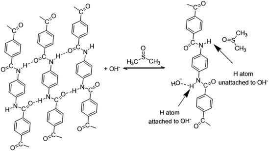
With further research, an improved hypothesis was proposed in the present work (Scheme 1). It was possible that the addition of water created more OH− in the system, which essentially accelerated the dissociation.52,53 KOH hydrolysed in H2O and formed OH−. On the molecular level, the oxygen atom in OH− had a denser electron atmosphere due to the extra electron, and was consequently more competitive in the formation of H-bonds than the oxygen atom in C![[double bond, length as m-dash]](https://www.rsc.org/images/entities/char_e001.gif) O. Thus, OH− would form a hydrogen bond with the hydrogen atom in secondary amide in aramid fibers, replacing the original inter–intramolecular hydrogen bonds. This contributed to the dissociation of macromolecules, and the resulting ANFs were further stabilized by DMSO in the system. The oxygen atom in DMSO could serve as the hydrogen bonding receptor for the unattached hydrogen atoms. Finally, the aramid fibers were transformed to ANFs. Therefore, increasing the concentration of OH− in the system may create a kinetic advantage and thus further accelerate the reaction (eqn (5)–(7)).
O. Thus, OH− would form a hydrogen bond with the hydrogen atom in secondary amide in aramid fibers, replacing the original inter–intramolecular hydrogen bonds. This contributed to the dissociation of macromolecules, and the resulting ANFs were further stabilized by DMSO in the system. The oxygen atom in DMSO could serve as the hydrogen bonding receptor for the unattached hydrogen atoms. Finally, the aramid fibers were transformed to ANFs. Therefore, increasing the concentration of OH− in the system may create a kinetic advantage and thus further accelerate the reaction (eqn (5)–(7)).
 | (5) |
| PPTA + OH− ⇆ PPTA⋯OH− | (6) |
| PPTA + KOH ⇆ PPTA⋯OH− + K+ | (7) |
Eqn (7) represents the total reaction.
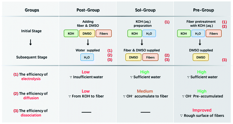
Based on the above analysis, the concentration of free OH− in the system should be increased as much as possible to expedite the entire preparation process of ANFs. The efficiency of the preparation was a joint result of multiple factors, mainly including (I) the efficiency of KOH electrolysis, (II) the efficiency of OH− diffusion to the fiber surface, and (III) the efficiency of aramid fiber dissociation.
Based on the analysis above, attempts were proposed for efficient preparation of ANFs as demonstrated in Scheme 2. The first method (Post-Group) was to add water into the KOH/DMSO system. This method had been reported by our previous work and was considered as a control group in the present work.3 Water could assist the dissociation of KOH and higher c(OH−) would be obtained than the pure KOH/DMSO system. An improvement in kinetic aspect was to perform the electrolysis of KOH in advance (Sol-Group). KOH solution rather than KOH solid was added to aramid/DMSO. This would greatly accelerate the efficiency of KOH electrolysis. Further adaption could be made to gain kinetic advantages (Pre-Group). The aramid fiber was immersed in pre-acquired KOH solution. Thus, OH− would directly gather around the fiber surface. In the next section, these groups were studied to verify the kinetic-originated hypothesis, from the aspects of product morphology and preparation efficiency.
3.2 Microstructure of ANFs fabricated by different methods
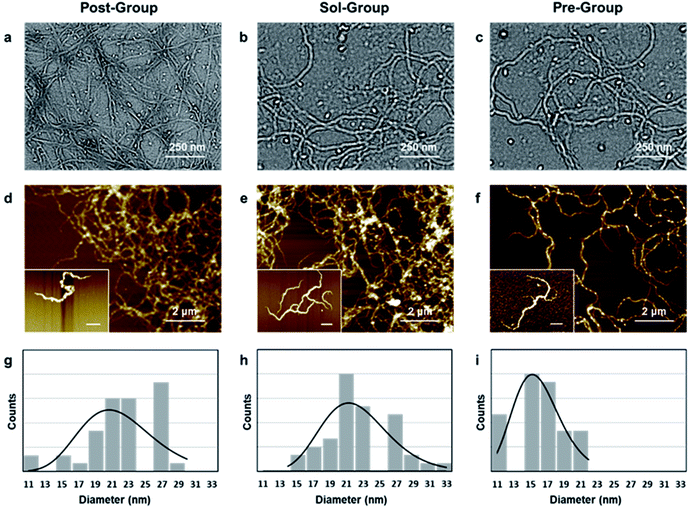
In order to verify whether the kinetic-advantaged strategies could successfully prepare ANFs, the microstructures of the products prepared by the above groups were characterized (Fig. 1).The TEM images corresponding to the above three groups all showed a large number of nanofibers (Fig. 1a–c), and the corresponding AFM images also showed uniformly dispersed nanofibers (Fig. 1d–f), which further supported the TEM image results. The ANF diameter obtained by the three methods was statistically analysed. The diameter was in the range of 10–30 nm and showed a narrow distribution (Fig. 1g–i), which was favoured for preparing macroscopic materials. The above results indicated that all three groups could successfully form ANFs.
In order to further observe the micromorphology of ANFs, the dispersion was further diluted to obtain the micromorphology of an individual fiber, which had rarely been reported previously. It was observed that Sol-ANFs and Pre-ANFs had a certain degree of branching. The branching might be the consequence of the more vigorous reaction, which attributed to the higher c(OH−) in the system. This could be potentially beneficial to ANF-based macroscopic materials, because branching could create more fiber winding and hydrogen bonds.
3.3 Reaction time and rate of ANFs by the three methods
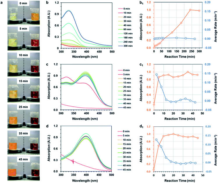
The study above confirmed that the three strategies could successfully prepare ANFs. The next key issue was the preparation efficiency. In order to compare the efficiency of nanofiber preparation, the reaction time and average reaction rate of the three strategies were further studied.The reaction rate was visually examined firstly (Fig. 2a). At the very beginning, the color of the two groups showed a significant contrast. The Post-Group remained colorless, while the Pre-Group turned orange immediately. This indicated that reaction occurred rapidly after DMSO was added in the system. The color of the Post-group gradually changed, but was still far from the typical state of the ANF dispersion (wine-colored) even after 45 min. The Pre-Group, surprisingly, showed a very rapid color change and reached the typical state of ANF dispersion after only 15 min.
In addition to the visual inspection, more accurate methods were necessary in order to study the preparation efficiency of ANFs more accurately. The ANFs had specific absorption peaks in the UV-vis region.45 Thus, the curves of the specific UV-vis absorptions were used to characterize the reaction process. The differentiated curves reflected the average reaction rate, and the end point corresponded to the point when the value turned 0.
The UV-vis absorption curves of Post-ANFs, Sol-ANFs and Pre-ANFs are shown in Fig. 2b–d, respectively. The reaction time curves and average reaction rate curves are presented in Fig. 2b1–d1 after normalization. The results showed that the Post-Group reached the end point after 300 min, which was in accordance with previous reports.36,44 For the Sol-Group, the end point occurred after 20 min, and for the Pre-Group, the end point occurred after only 13 min. The efficiency proved that, with the kinetic advantage, the preparation efficiency was considerably higher. The Pre-Group, which was designed to be the most kinetic-advantaged, showed the fastest method for preparing ANFs reported at present (Table S3†). These results proved that the formation of ANFs in this system was indeed a kinetic-controlled process. The kinetic-advantage strategy could skip or effectively accelerate some “rate-determining steps”, thus improving the overall efficiency.
In addition, the pre-treatment of aramid fibers might bring other benefits. In order to further explore the influence of pre-treatment, the microstructure of treated aramid fibers was observed (Fig. S1†). There were a large number of crystals on the fiber surface after the immersion in KOH solution, indicating that pre-treatment could create high c(OH−) directly around the fiber surface. Moreover, the fiber surface appeared to be rough, indicating that the skin layer was destructed after pre-treatment. The possible reason was that aramid fibers have reacted with OH− at high concentrations. The pre-treatment would enlarge the contact surfaces, which was an additional benefit to the subsequent reaction.
3.4 Morphological evolutions and chemical structure changes in the formation process
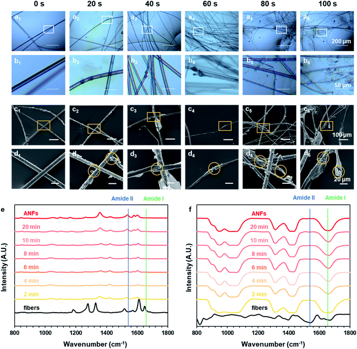
How did macro-fibers dissociate into nanofibers in the ultra-fast process? Did any difference emerge when the process was greatly accelerated? To explore these, the preparation process was recorded and analysed at different preparation times, revealing the morphology evolution and formation mechanism. Fig. 3a–d shows the morphological evolution of aramid fibers in the time rage of 0–100 s. An optical microscope was used to follow the real-time status of fibers (Fig. 3a and b), while SEM observation was also used to catch the detail of morphology (Fig. 3c and d).We have previously observed the dissociation of fibers parallel to the axial direction to form nanofibers.44 In this paper we observed the dissociation of fibers perpendicular to the axial direction. The joint action of these two phenomena enabled us to have a further understanding of the dissociation of macroscopic aramid fibers into nanofibers. After pre-treatment, the fiber surface became rough, indicating that the skin layer was destructed at certain sites (Fig. 3c1 and d1). This could give OH− the access to the interior of the fibers. At these sites, the fibers further appeared to be swelled (Fig. 3b3 and d3), facilitating the diffusion of OH− to the interior of the fibers. Finally, the aramid fiber was fractured perpendicular to the axial direction (Fig. 3b4 and d4). The above information suggested that, during the formation of ANFs, the macroscopic fibers dissociated along and perpendicular to the axis direction, simultaneously.
In addition to the evolution of fiber morphology, the changes of chemical structure during the preparation process were also very important. The Raman and FT-IR spectra of aramid fibers and ANFs all showed typical characteristic peaks (Fig. 3e and f and Tables S4 and S5†), which was in accordance with previous studies.54–56 The results of spectra showed that the chemical nature of resulting ANFs was well preserved, although the reaction rate had been greatly accelerated by the pre-treatment method. The intensity of characteristic peaks gradually increased with the increase of time, indicating the continuous growth of c(ANFs) in the system. The spectra corresponding to different preparation times all showed characteristic peaks of ANFs, with identical relative peak intensity. This indicated that the product was ANFs in the entire process. The characteristic peak of ANFs showed a broader half-peak width than that of aramid fibers in Raman spectra, indicating that the order and crystallinity were reduced. Some shifts of peaks attributed to the influence of the solvent were also observed.
The characteristic peaks also revealed additional information on the molecular state of aramid. A characteristic peak corresponding to the amide I band (Fig. S2†) mainly showed information of stretching vibration of C![[double bond, length as m-dash]](https://www.rsc.org/images/entities/char_e001.gif) O (1650 cm−1); a characteristic peak corresponding to the amide II band mainly showed information of stretching and bending vibration of N–H (1535 cm−1). When aramid fiber was transformed to ANFs, based on the hypothesis, OH− formed a hydrogen bond with the hydrogen atom in secondary amide in aramid, replacing the original hydrogen bond between C
O (1650 cm−1); a characteristic peak corresponding to the amide II band mainly showed information of stretching and bending vibration of N–H (1535 cm−1). When aramid fiber was transformed to ANFs, based on the hypothesis, OH− formed a hydrogen bond with the hydrogen atom in secondary amide in aramid, replacing the original hydrogen bond between C![[double bond, length as m-dash]](https://www.rsc.org/images/entities/char_e001.gif) O and N–H.57,58 After dissociation, the unattached N–H was stabilized by DMSO, with oxygen atoms in S
O and N–H.57,58 After dissociation, the unattached N–H was stabilized by DMSO, with oxygen atoms in S![[double bond, length as m-dash]](https://www.rsc.org/images/entities/char_e001.gif) O serving as the hydrogen bonding receptor. Thus, the hydrogen bond associated with C
O serving as the hydrogen bonding receptor. Thus, the hydrogen bond associated with C![[double bond, length as m-dash]](https://www.rsc.org/images/entities/char_e001.gif) O was weakened, while the hydrogen bond associated with N–H was retained or even enhanced. The change in the density of electron atmosphere could be revealed by information from spectra. When aramid fibers were transformed to ANFs, amide I could not be observed in Raman spectra, indicating that the symmetric vibration of C
O was weakened, while the hydrogen bond associated with N–H was retained or even enhanced. The change in the density of electron atmosphere could be revealed by information from spectra. When aramid fibers were transformed to ANFs, amide I could not be observed in Raman spectra, indicating that the symmetric vibration of C![[double bond, length as m-dash]](https://www.rsc.org/images/entities/char_e001.gif) O was weakened. On the contrary, amide II could not be observed in FT-IR spectra, indicating that the asymmetric vibration of N–H was weakened. These results indicated that the change in electron atmosphere density and the change of H-bonds on amide bonds were associated. The hypothesis was reasonable in describing the nature of ANF formation. Thus, creating a condition with a kinetic advantage was essential to the effective formation of ANFs.
O was weakened. On the contrary, amide II could not be observed in FT-IR spectra, indicating that the asymmetric vibration of N–H was weakened. These results indicated that the change in electron atmosphere density and the change of H-bonds on amide bonds were associated. The hypothesis was reasonable in describing the nature of ANF formation. Thus, creating a condition with a kinetic advantage was essential to the effective formation of ANFs.
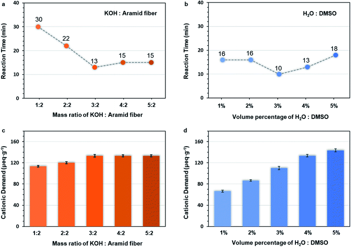
3.5 Effect of different dosage of KOH and water on the preparation of Pre-ANFs
In order to further elucidate the ultra-fast ANF formation process, two influencing factors were investigated, namely, the dosage of alkali (Table S1†) and water (Table S2†). The c(OH−) played a crucial role in the mechanism of formation, so the cationic demand was determined. Cationic demand corresponded to the number of anions in the system and indicated the concentration of OH−. The preparation time (Fig. 4a, b and S3–S12†) and the cationic demand of different groups (Fig. 4c and d) was evaluated.When the amount of KOH was increased, the preparation time decreased first and then increased (Fig. 4a), while the cationic demand increased first and then remained stable (Fig. 4c). This could be explained as follows. When the mass ratio of KOH/aramid fiber was lower than 3![[thin space (1/6-em)]](https://www.rsc.org/images/entities/char_2009.gif) :
:![[thin space (1/6-em)]](https://www.rsc.org/images/entities/char_2009.gif) 2, the system was unsaturated for OH−, so the reaction was accelerated with the increase of c(OH−). The changes of cationic demand confirmed that the c(OH−) gradually increased (Fig. 4c), and the system finally became saturated. Over this point, higher supply of KOH would precipitate as crystals on the fiber surface, which decreased the effective contact surface of fibers.
2, the system was unsaturated for OH−, so the reaction was accelerated with the increase of c(OH−). The changes of cationic demand confirmed that the c(OH−) gradually increased (Fig. 4c), and the system finally became saturated. Over this point, higher supply of KOH would precipitate as crystals on the fiber surface, which decreased the effective contact surface of fibers.
When the amount of water was increased, the preparation time decreased first and then increased (Fig. 4b), while the cation demand increased monotonically (Fig. 4d). When the water supply was low, the c(OH−) was limited due to the lack of water. Excess KOH would precipitate on the fiber surface, which impeded the reaction. In this range, increasing water content in the system could facilitate the dissociation of KOH, thus increasing the c(OH−) and shortening the preparation time. However, over-supply of water might also be unfavourable even though the c(OH−) increased because over-supply of water changed the solubility parameter δmix of the system and made the system unsuitable (demonstrated in the ESI†) for PPTA,51 making the stable dispersion of ANFs impossible.
The above results further confirmed that the c(OH−) played a decisive role, and the preparation of ANFs was dominated by kinetics.
3.6 Performance of ANF membranes
In order to verify the performance of the ANFs prepared by the ultra-fast method, ANF-based membranes were prepared and evaluated in terms of micromorphology, mechanical strength, thermal stability, light transmittance, and electrical insulation.ANF membranes prepared by the three methods all showed a typical structure with interwoven and entangled nanofibers (Fig. 5). This laid the foundation of excellent mechanical, optical and electrical insulation properties.
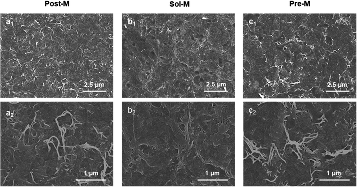 | ||
| Fig. 5 SEM images of ANF membranes (a1) for Post-M, (b1) for Sol-M, (c1) for Pre-M, (a2–c2) were zoom images, respectively). | ||
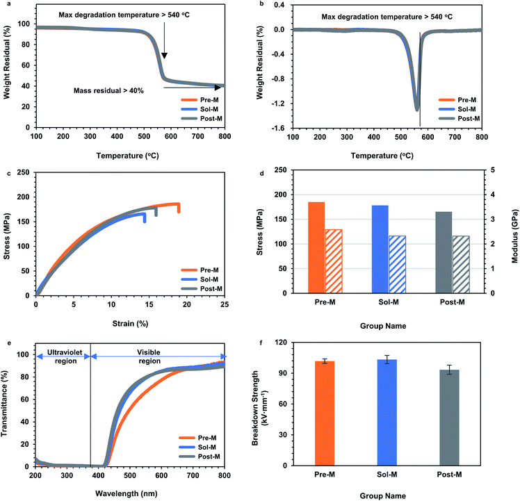
As demonstrated in the Introduction, ANFs showed prominent thermostability, excellent mechanical properties, light transmission and insulation ability.3 These properties were also critical for subsequent applications. Thus, to determine whether a strategy was ideal for ANF preparation, it was necessary to examine whether the ANF-based materials successfully achieved these properties. Thermogravimetric analysis (TGA) was performed to test the thermal stability of ANF membranes (Fig. 6a and b). The TGA curves of the ANF membranes from the three groups almost overlapped. The ANF membranes still had residual mass over 40% at 800 °C, and the maximum decomposition temperature was above 540 °C. The results showed that the acceleration of preparation rate did not affect the thermal stability of ANFs. Tests on tensile strength were performed to evaluate the mechanical property. The tensile stress of the three kinds of membranes was almost the same, with strain above 12.5% and tensile strength above 160 MPa (Fig. 6c and d). This indicated that the membranes constructed by ANFs all had excellent mechanical properties. The microstructure of ANFs had a slight effect on the mechanical properties of the membrane. The Pre-M showed a larger strain, which might be the result of the branching of Pre-ANFs. Branching could create more interlacing and winding, and resulted in larger ultimate deformation. UV-vis transmittance tests were adopted to evaluate the light transmission. ANF membranes from the three methods all showed UV shielding performance as well as good light transmittance in the visible region (Fig. 6e), which were typical characteristic for 2D ANF materials.59
Since aramid fiber was often used in the field of electrical insulation,10,11,60 it was particularly important to investigate the electrical breakdown properties (Fig. 6f). The electrical breakdown strength of all the ANF membranes surpassed 90 kV mm−1. This value was much higher than the breakdown strength of commercial aramid fiber paper, because the entangled nanofibers in the ANF membranes formed a dense structure compared with aramid paper (Fig. 5c). This indicated that ANFs had the potential to form a new generation of electrical insulation membranes and promote the upgrade of a new generation of aramid insulating materials. Performance evaluation proved that the ANF materials from the ultra-fast method showed typical excellent properties, in the aspects of thermostability, mechanical properties, light transmission and insulation. The essential characteristics of aramid nanofibers were retained when the preparation was greatly accelerated.
4. Conclusion
With analysis from the perspective of kinetics, the present work offered a long-sought strategy to accomplish a rapid and successful preparation of ANFs. In particular, the Pre-Group with the kinetic-advantage significantly shortened the preparation time to 10 minutes, which was a considerable step forward. The results proved that the formation of ANFs was a kinetic-controlled process, and the c(OH−) showed decisive influence. The kinetic-originated hypothesis and the related research might shed new light on the nature of ANF preparation. New information on morphology evolution was also obtained, indicating that the aramid fibers dissociated along and perpendicular to the axis direction simultaneously. The ANF materials from the ultra-fast method also showed excellent properties, in terms of mechanical strength (tensile strength > 160 MPa), thermal stability, light transmittance, and electrical insulation (above 90 kV mm−1). This work not only presented an ultra-fast way for ANF formation, which was favourable for large-scale production, but also provided a new view-point on the formation mechanism, which would benefit the functionalization and diversification utilization of ANF-based materials.Author contributions
Lianqing Huang: conceptualization, investigation, data curation, writing – original draft, and writing – review & editing. Jingyi Nie: supervision, methodology, investigation, funding acquisition, and writing – review & editing. Bin Yang: investigation, funding acquisition and supervision. Meiyun Zhang: project administration and funding acquisition. Shunxi Song: investigation and funding acquisition. Jiaojun Tan: investigation.Conflicts of interest
The authors declare that they have no known competing financial interests or personal relationships that could have appeared to influence the work reported in this paper.Acknowledgements
This study was supported by the Foundation of Science and Technology project of Shaanxi Province (2020JQ-704), China Postdoctoral Science Foundation (Program No. 2020M683409, 2021T140434, 2020M683411), the National Natural Science Foundation of China (Program No. 22008146), Key Research and Development Program of Shaanxi Province of China (Program No. 2021ZDLGY14-05), Innovation Capability Support Program of Shaanxi (Program No. 2020KJXX-082), the Foundation (No. 202005) of Tianjin Key Laboratory of Pulp & Paper (Tianjin University of Science & Technology), and Natural Science Foundation of Shaanxi Province of China (Program No. 2020JQ-727).References
- S. H. Cha, J. U. Kim and J. C. Lee, Macromol. Res., 2008, 16, 711–716 CrossRef CAS
.
- J. Zhou, W. Li, X. Dong, Y. Qiang, J. Wang, H. Yu and C. Xu, Eur. Polym. J., 2010, 43, 1736–1743 CrossRef
.
- M. Yang, K. Cao, L. Sui, Y. Qi, J. Zhu, A. Waas, E. M. Arruda, J. Kieffer, M. D. Thouless and N. A. Kotov, ACS Nano, 2011, 5, 6945–6954 CrossRef CAS PubMed
.
- M. Yang, K. Cao, B. Yeom, M. D. Thouless, A. Waas, E. M. Arruda and N. A. Kotov, J. Compos. Mater., 2015, 49, 1873–1879 CrossRef CAS
.
- W. X. Cao, L. Yang, X. D. Qi, Y. Hou, J. Q. Zhu and M. Yang, Adv. Funct. Mater., 2017, 27, 1701061 CrossRef
.
- J. Fan, Z. Shi, L. Zhang, J. Wang and J. Yin, Nanoscale, 2012, 4, 7046–7055 RSC
.
- K. Cao, C. P. Siepermann, M. Yang, A. M. Waas, N. A. Kotov, M. D. Thouless and E. M. Arruda, Adv. Funct. Mater., 2013, 23, 2072–2080 CrossRef CAS
.
- Q. Kuang, D. Zhang, J. C. Yu, Y. W. Chang, M. Yue, Y. Hou and M. Yang, J. Phys. Chem. C, 2015, 119, 27467–27477 CrossRef CAS
.
- Y. Guan, W. Li, Y. Zhang, Z. Shi, J. Tan, F. Wang and Y. Wang, Compos. Sci. Technol., 2017, 144, 193–201 CrossRef CAS
.
- B. Yang, M. Zhang, Z. Lu, J. Luo, S. Song, J. Tan and Q. Zhang, Composites, Part B, 2018, 154, 166–174 CrossRef CAS
.
- B. Yang, M. Zhang, Z. Lu, J. Luo, S. Song and Q. Zhang, ACS Sustainable Chem. Eng., 2018, 6, 8954–8963 CrossRef CAS
.
- L. Wang, M. Zhang, B. Yang, J. Tan and X. Ding, ACS Nano, 2020, 14, 10633–10647 CrossRef CAS PubMed
.
- L. Wang, M. Zhang, B. Yang, X. Ding, J. Tan, S. Song and J. Nie, ACS Appl. Mater. Interfaces, 2021, 13, 5486–5497 CrossRef CAS PubMed
.
- S. O. Tung, S. Ho, M. Yang, R. Zhang and N. A. Kotov, Nat. Commun., 2015, 6, 6152 CrossRef CAS PubMed
.
- S. O. Tung, S. L. Fisher, N. A. Kotov and L. T. Thompson, Nat. Commun., 2018, 9, 4193 CrossRef PubMed
.
- S. Hu, S. Lin, Y. Tu, J. Hu, Y. Wu, G. Liu, F. Li, F. Yu and T. Jiang, J. Mater. Chem. A, 2016, 4, 3513–3526 RSC
.
- J. L. Li, W. T. Tian, H. C. Yan, L. Y. He and X. L. Tuo, J. Appl. Polym. Sci., 2016, 133, 43623 Search PubMed
.
- C. Q. Zhu, J. X. Zhang, J. Xu, X. Z. Yin, J. Wu, S. H. Chen, Z. M. Zhu, L. X. Wang and H. Wang, J. Membr. Sci., 2019, 588, 117169 CrossRef CAS
.
- B. Yang, L. Wang, M. Zhang, W. Li, Q. Zhou and L. Zhong, J. Mater. Chem. A, 2021, 9, 12923–12946 RSC
.
- J. Zhu, W. Cao, M. Yue, H. Ying and M. Yang, ACS Nano, 2015, 9, 2489–2501 CrossRef CAS PubMed
.
- Z. Ma, S. Kang, J. Ma, L. Shao, A. Wei, C. Liang, J. Gu, B. Yang, D. Dong, L. Wei and Z. Ji, ACS Nano, 2019, 13, 7578–7590 CrossRef CAS PubMed
.
- J. Fan, Z. Shi, M. Tian and J. Yin, RSC Adv., 2013, 3, 17664–17667 RSC
.
- J. Lyu, X. Wang, L. Liu, Y. Kim, E. K. Tanyi, H. Chi, W. Feng, L. Xu, T. Li, M. A. Noginov, C. Uher, M. D. Hammig and N. A. Kotov, Adv. Funct. Mater., 2016, 26, 8435–8445 CrossRef CAS
.
- T. Y. Zhou, J. G. Boyd, D. Loufakis, J. L. Lutkenhaus and D. C. Lagoudas, Smart Mater. Struct., 2019, 28, 094001 CrossRef CAS
.
- Y. Zhao, S. Zhang, F. Hu, J. Li, H. Chen, J. Lin, B. Yan, Y. Gu and S. Chen, J. Mater. Sci.: Mater. Electron., 2019, 30, 12718–12728 CrossRef CAS
.
- Y. Li, G. Ren, Z. Zhang, C. Teng, Y. Wu, X. Lu, Y. Zhu and L. Jiang, J. Mater. Chem. A, 2016, 4, 17324–17332 RSC
.
- S. Aderyani, P. Flouda, J. L. Lutkenhaus and H. Ardebili, J. Appl. Phys., 2019, 125, 185106 CrossRef
.
- S. R. Kwon, M. B. Elinski, J. D. Batteas and J. L. Lutkenhaus, ACS Appl. Mater. Interfaces, 2017, 9, 17125–17135 CrossRef CAS PubMed
.
- Y. Liu, K. Zhang, Y. Mo, L. Zhu, B. Yu, F. Chen and Q. Fu, Compos. Sci. Technol., 2018, 168, 28–37 CrossRef CAS
.
- Z. Peng, Y. Yang, J. Luo, C. Nie, L. Ma, C. Cheng and C. Zhao, Biomater. Sci., 2016, 4, 1392–1401 RSC
.
- Y. Yuan, J. Li, Y. Liu, T. Chen and J. Lin, Polym. Compos., 2018, 39, 2411–2419 CrossRef CAS
.
- C. Nie, Y. Yang, Z. Peng, C. Cheng, L. Ma and C. Zhao, J. Membr. Sci., 2017, 528, 251–263 CrossRef CAS
.
- Y. Li, S. Yuan, C. Zhou, Y. Zhao and B. Van der Bruggen, J. Mater. Chem. A, 2018, 6, 22987–22997 RSC
.
- Z. Cheng, Z. Bai, Y. Dai, L. Luo and X. Liu, Analyst, 2018, 143, 5225–5233 RSC
.
- B. Yang, L. Wang, M. Y. Zhang, J. J. Luo, Z. Q. Lu and X. Y. Ding, Adv. Funct. Mater., 2020, 30, 2000186 CrossRef CAS
.
- B. Yang, W. Li, M. Zhang, L. Wang and X. Ding, ACS Nano, 2021, 15, 7195–7207 CrossRef CAS PubMed
.
- A. Greiner and J. H. Wendorff, Angew. Chem., Int. Ed. Engl., 2007, 46, 5670–5703 CrossRef CAS PubMed
.
- J. H. Kim, S. H. Lee, B. C. Ku and Y. S. Chung, Mater. Lett., 2011, 59, 4044–4047 Search PubMed
.
- J. Stendahl, M. Rao, M. Guler and S. Stupp, Adv. Funct. Mater., 2006, 16, 499–508 CrossRef CAS
.
- H. Sehaqui, K. Kulasinski, N. Pfenninger, T. Zimmermann and P. Tingaut, Biomacromolecules, 2017, 18, 242–248 CrossRef CAS PubMed
.
- Y. Jian, J. Jin, E. Lepore, N. M. Pugno and T. Peijs, Macromol. Mater. Eng., 2016, 300, 1238–1245 Search PubMed
.
- H. C. Yan, J. L. Li, W. T. Tian, L. Y. He, X. L. Tuo and T. Qiu, RSC Adv., 2016, 6, 26599–26605 RSC
.
- S. Ifuku, H. Maeta, H. Izawa, M. Morimoto and H. Saimoto, RSC Adv., 2014, 4, 40377–40380 RSC
.
- B. Yang, L. Wang, M. Zhang, J. Luo and X. Ding, ACS Nano, 2019, 13, 7886–7897 CrossRef CAS PubMed
.
- J. M. Koo, H. Kim, M. Lee, S. A. Park, H. Jeon, S. H. Shin, S. M. Kim, H. G. Cha, J. Jegal, B. S. Kim, B. G. Choi, S. Y. Hwang, D. X. Oh and J. Park, Macromolecules, 2019, 52, 923–934 CrossRef
.
- R. R. Burch, W. Sweeny, H. W. Schmidt and Y. H. Kim, Macromolecules, 1990, 23, 1065–1072 CrossRef CAS
.
- H. J. Chen, Q. Y. Bai, M. C. Liu, G. Wu and Y. Z. Wang, Green Chem., 2021, 23, 7646–7658 RSC
.
-
P. Ptáek, T. Opravil and F. Oukal, A Brief Introduction to the History of Chemical Kinetics, Introducing the Effective Mass of Activated Complex and the Discussion on the Wave Function of This Instanton, 2018 Search PubMed
.
- G. Feher and M. Weissman, Proc. Natl. Acad. Sci. U. S. A., 1973, 70, 870–875 CrossRef CAS PubMed
.
- A. Ghysels, T. Verstraelen, K. Hemelsoet, M. Waroquier and V. V. Speybroeck, J. Chem. Inf. Model., 2010, 50, 1736–1750 CrossRef CAS PubMed
.
- K. I. Oh, K. Rajesh, J. F. Stanton and C. R. Baiz, Angew. Chem., Int. Ed. Engl., 2017, 56, 11375–11379 CrossRef CAS PubMed
.
- N. M. Vitkovskaya, V. B. Orel, V. B. Kobychev, A. S. Bobkov, E. Y. Larionova and B. A. Trofimov, J. Phys. Org. Chem., 2017, 30, 3669 CrossRef
.
- V. B. Orel, N. M. Vitkovskaya, V. B. Kobychev and B. A. Trofimov, J. Org. Chem., 2018, 83, 3719–3726 CrossRef CAS PubMed
.
- P. K. Kim, C. Chang and S. L. Hsu, Polymer, 1986, 27, 34–46 CrossRef CAS
.
- G. Washer, T. Brooks and R. Saulsberry, J. Mater. Civ. Eng., 2009, 21, 226–234 CrossRef CAS
.
- S. M. Shebanov, I. K. Novikov, A. V. Pavlikov, O. B. Anańin and I. A. Gerasimov, Fibre Chem., 2016, 48, 158–164 CrossRef CAS
.
- Z. Wang, J. Nie, W. Qin, Q. Hu and B. Z. Tang, Nat. Commun., 2016, 7, 12033 CrossRef PubMed
.
- L. J. Karas, C.-H. Wu, R. Das and J. I. C. Wu, Wiley Interdiscip. Rev.: Comput. Mol. Sci., 2020, 10, e1477 CAS
.
- J. Luo, M. Zhang, B. Yang, G. Liu, J. Tan, J. Nie and S. Song, Carbohydr. Polym., 2019, 203, 110–118 CrossRef CAS PubMed
.
- Z. Lu, L. Si, W. Dang and Y. Zhao, Composites, Part A, 2018, 115, 321–330 CrossRef CAS
.
Footnote |
| † Electronic supplementary information (ESI) available. See DOI: 10.1039/d1na00897h |
| This journal is © The Royal Society of Chemistry 2022 |

