 Open Access Article
Flow-induced-crystallization: tailoring host–guest supramolecular co-assemblies at the liquid–solid interface†
Yi
Hu‡
 ,
Xingming
Zeng‡
,
Sanjay
Sahare
,
Rong-Bin
Xie
and
Shern-Long
Lee
,
Xingming
Zeng‡
,
Sanjay
Sahare
,
Rong-Bin
Xie
and
Shern-Long
Lee
 *
*
Institute for Advanced Study, Shenzhen University, Shenzhen 518060, China. E-mail: sllee@szu.edu.cn
First published on 15th June 2022
Abstract
Here, we report that using the method of simply contacting a sample solution droplet with a piece of tissue paper can create a solvent flow (capillary force). During this process, the dynamics and solvent removal can promote the formation and stabilization of a meta-stable linear quasi-crystal composed of p-terphenyl-3,5,3′,5′-tetracarboxylic acid (TPTC) molecules, which would otherwise pack into thermodynamically favored random tiling. The tailored quasi-crystal (linear) template allows atop it higher-efficiency accommodation of fullerene molecules (C60) from 40.1% to 97.5%, compared with that obtained in the random-tiling (porous) case. Overall, the result of this study presents an unusual yet remarkably simple strategy for tailoring complex host–guest supramolecular systems at the liquid–solid interface.
Introduction
Host–guest supramolecular interactions occur ubiquitously in nature, which underpins most processes and decisions in the bio-system, such as the synthesis of functional proteins and protein complexes.1 Inspired by nature, chemists have devoted themselves to developing supramolecular methods for yielding complicated complexes with desired functions, aimed at constructing molecule-based devices including organic photovoltaics (OPVs), field-effect transistors (OFETs), and light-emitting diodes (OLEDs).2–4 To achieve highly efficient device performances, it requires precise ordering over organic materials on a solid surface at the nanoscale level.5 The advantages of molecular-based electronics include uniformity in molecular size; however, an overwhelming diversity arises due to the occurrence of polymorphism defined as the existence of more than one type of structure for a given molecule.6 This can occur not only for intrinsic molecular frameworks but also for their two-dimensional (2D) self-assembled structures, both of which can affect largely the device performance. Usually, a scanning tunneling microscope (STM) is used to explore materials and their self-assembled motifs physisorbed on a solid surface, amenable to in situ STM monitoring, from which one can obtain information about kinetics and thermodynamics.7 The molecular assemblies formed from building blocks can also change locally and globally in response to external stimuli, so-called stimuli-responsive systems, receiving perpetual interest from a broad range of research fields.8–13In the host–guest supramolecular system, templating is a well-received strategy for ordering functional guest molecules.14,15 For example, a fullerene (e.g., C60) has been widely used as the electron acceptor in organic solar-cell devices. Due to its high mobility and the lack of substitutes, C60 self-assemblies are hardly formed unless in low-temperature/ultra-vacuum (LT-UHV) environments and on metal surfaces such as Au(111), Ag(111), and Cu(111),3,7 as well as other solid substrates like SrTiO3(100).16 Alternatively, using organic molecular assemblies has been a significant method to template C60 molecules under ambient conditions. In this regard, organic chemists have focused on rational design for producing molecular tectonics according to targeted guest molecules, although the synthesis difficulty of these templates remains a challenge. Besides van der Waals interaction, for energy material systems (e.g., including C60), it generally involves the conceptual design of charge transfer between the host and guest molecules to stabilize the donor–acceptor configurations. Examples of rationally synthesized templates include conjugated p-expanded macrocyclic oligothiophenes17,18 and other molecules that can constitute cavities in their assemblies.19,20
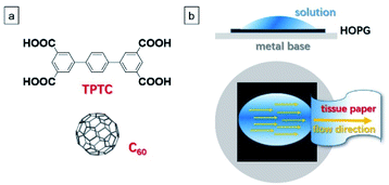
A significant topic in this research area is that the guest molecules can adsorb into a specific polymorph or one type of molecular network by preference, associated with selective co-assembly and phase separation science in the mixture.15,21 In the literature related to surface host–guest assembly, an interesting report is that 3D guest molecules can induce the formation of bilayer templates. Specifically, it was previously demonstrated that C60 can assist in the yielding of random-tiling bilayer templates composed of p-terphenyl-3,5,3′,5′-tetracarboxylic acid molecules (TPTC, Fig. 1a) at the liquid–solid interface.22 The present work aims to further explore this system.
Highly efficient performance in the aforementioned related devices necessitates high-density molecular packing. However, for the TPTC–C60 system, despite a saturated C60 concentration being used, it turns out unsuccessful for high-density accommodation in the random-tiling TPTC template. This may result from the position preference of C60 adsorption within the glass-like assemblies of TPTC as well as TPTC molecules rearrange frequently in the network.23 Here, using it as a model system, we show for the first time that the tailoring of the molecular template from random-tiling to crystals could yield close-packing C60 arrays to atop it. Note that the “close-packing” is relatively close if compared with the scenario of the random-tiling template where C60 molecules are adsorbed in a low-density fashion; the C60 molecules were separated by the template, meaning that they did not “touch” each other. This idea is based on stimuli-responsive manipulation and flow-induced crystallization, thereby steering the molecules and thus triggering the phase transition from disordered to well-ordered templates.24 In our procedure, a simple contact of the sample droplet with a piece of tissue paper was utilized to create a solvent flow (Fig. 1b and S1 in the ESI†)25 during which the dynamics and solvent removal took place, which was proposed to promote the formation and stabilization of a meta-stable linear (quasi)-crystal. The as-regulated template was able to trap C60 molecules in the desired close-packing fashion.
Experimental
All the STM experiments were conducted on a HOPG (quality ZYB, Bruker, USA) surface under ambient conditions (temperature: 20–25 °C; humidity: 45–50%), in constant current mode, using either a Keysight 5500 or a Bruker nanoscope IIIa system. Solvents: OA (1-octanoic acid, ≥99%). Target molecules: TPTC (≥95%); C60 (≥98%). These three molecules were commercially purchased and used without further purification. The STM tips were mechanically cut from Pt/Ir wires (80/20, diameter: 0.25 mm). The scanning parameters were described in the figure captions. The STM images were captured line-by-line via the STM tip. The scanning speed of the STM is constant, which was set as 0.602 μm s−1 in this work. The STM images were analyzed by using either WSxM or SPIP software. The proposed structural models were built based on the high-resolution STM images, using Materials Studio 7.0 software.Results and discussion
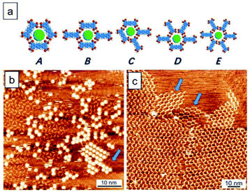
Fig. 2 shows the TPTC assembly and the TPTC–C60 complex. It has been previously reported that the TPTC molecules at the liquid–solid interface constitute a random-tilling network, whose formations rely on directional hydrogen bonds.23 The glass-like motifs present five types of voids including a different number of molecular networks, namely, A[triangle], B[parallelogram], C[arrow], D[semicircle], and E[star] at the OA-highly oriented pyrolytic graphite (HOPG) interface. For the TPTC packing and the TPTC–C60 complex, our simulations suggest that the C60 molecules are located in these cavities with different stability (Fig. 2a, Table S1† in the ESI†). Specifically, the force field simulations of the adsorption energies for the five pores on the HOPG surface were calculated to be −227.5, −227.7, −225.2, −228.4, and −228.7 kJ mol−1, respectively. According to the data, the five kinds of pores appear with similar energy from a theoretical viewpoint, consistent with STM investigations where diverse packing occurs.26,27 The adsorption energies of C60 inserted into the A–E pores were calculated to be −186.5, −181.1, −190.2, −153.7, and −152.0 kJ mol−1, respectively (Fig. 2a, Table S2† in the ESI†). The simulations suggest that C60 may stay in the A, B, or C pore ideally. Consistently, C60 molecules based on STM observations were located in these cavities by preference. This explains why the majority of the surface is low-density C60 packing (Fig. 2b).Intriguingly, a small percentage (∼10%) of this surface features close packing arrays of C60. This may be associated with the linear type B template underneath, as indicated by a blue arrow at the lower right corner in Fig. 2b. On the other hand, for TPTC assembly, the impurity exists as indicated by two arrows in Fig. 2c. They were referred to as structurally similar molecules of p-quaterphenyl-3,3′′′,5,5′′′-tetracarboxylic acid (QPTC) and p-quinquephenyl-3,3′′′,5,5′′′-tetracarboxylic acid (QQPTC). The two molecules show similar chemical structures with TPTC, differing from each other with the number of phenyl rings in their π-conjugated skeletons (Fig. S2†). QPTC and QQPTC could be the side-products during TPTC synthesis and have been proposed to induce linear packing and random-tiling bilayers of TPTC.28
To form close packing C60, one can envisage that the formation of a linear type B template is required. However, it is impractical to generate such a polymorph over the whole surface through impurity induction. Although temperature-modulation can be a strategy to select polymorphic forms,29,30 thermal treatments may fail to generate the linear type B template as the thermodynamically favored random tiling is the final state in the system.23 To this end, we use a flow method described in Fig. 1 to generate the desired linear networks. Thus far, the flow effect on host–guest systems has not been attempted yet.25,31,32 Significantly, this work nicely demonstrates how macroscopic force can affect microscopic supramolecular behavior and host–guest assembly, especially at molecular level precision.
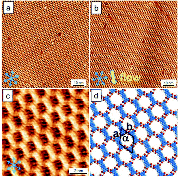
First of all, we discuss the template behavior in response to the flow treatment. To form monolayers, the sample solution concentration of TPTC was diluted to 10% from saturation. Fig. 3a and b show the typical surfaces of TPTC assembly prepared without and with the flow treatment. Fig. 3c and d exhibit the high-resolution STM image and the corresponding type B model. Note that the molecular network includes type B pores but impurities come into play.28 We thus name this a “quasi” crystal because the impurities are involved in/between the type B packing, resulting in a non-periodic network when considering the whole assembly. After about 6 hours, around 5% of the quasi-crystal was transformed into random tiling, indicating that the linear packing is kinetically stabilized, whereas the random tiling is thermodynamically preferred. Moreover, compared to the linear, the less ordered random tiling is favored for the entropy reason.23 Slower dynamics occur, ascribed to the almost dried surface compared with that in the case of a normal liquid–solid interface. For the common scenario, the random tiling is dominant at a low sample concentration.
Note that although it is well known that concentration variation can drastically affect molecular self-assembly at surfaces,33 here the flow method led to the yielding of the kinetic form of the linear TPTC template. We used the flow to tailor the host polymorph. Such a meta-stable polymorphic form was not simply formed by increasing the TPTC concentration as a saturated sample solution in general results in random-tiling packing and even vertical stacking. Our flow induced the formation and stabilization of the linear TPTC template.
On the other hand, for a saturation concentration and without flow, linear packing with multiple small domains can appear spontaneously (Fig. S3†), which may result from abundant seeds and subsequent crystal growth simultaneously.27,28 Being a kinetic form, they can entirely transition to glass-like structures after a long time of STM running (e.g., 6 hours, Fig. S3†). Meanwhile, some random-tiling bilayers can appear when the saturated sample solution includes TPTC solids or powders (e.g., super-saturation).34 The presence of these impurities has also been proposed to cause bilayer formation in the literature.28 Despite being a perplexing system, after being subjected to the flow treatment, they can readily transfer to linear packing as repeated by our experiments. The phase transformations are prompt (e.g., 3–5 seconds) after applying the flow. Fig. S4† shows more STM images of the phase transition triggered by the flow method.
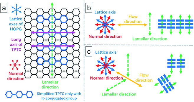
As shown in Fig. 3, STM revealed that the molecular long axis is along one of the normal axes of the HOPG lattice, and the lamellae of the TPTC monolayer are orthogonal to the flow. To form a uniform and large domain of linear packing, the flow was deliberately applied to the normal direction. To explain this comprehensively, Fig. 4 illustrates the relationship between the flow, molecular patterning, and substrate. The HOPG lattice axes can be determined by the STM tool. Fig. 4a defines the direction and relationship of the TPTC axes and the substrate. Fig. 4b and c show the scenario where the flow is applied to the normal and one of the axes of HOPG, respectively. It can be envisaged that a uniform patterning can take place for the former whereas mirror packing can occur for the latter. The results were ascribed to the possibilities of molecular adsorption and thus their assembly over the surface after the flow treatment. Based on the analysis, for relatively uniform patterning, the flow has thus to be applied along the “normal” direction of HOPG in our experiments.
In addition, from experimental results, we note that the long axis of TPTC runs along lattice axes and the normal direction for random-tiling and linear packing, respectively. The former is consistent with the literature report23 and the latter is reported for the first time. It can deviate 6° from the axes such that 12° rotation between domains of the TPTC networks can be noticed.23
In short, the flow can induce and is more promising to generate large area linear packing (the result was examined and is shown in Fig. S5 in the ESI†). Also, as reported in the literature, longer impurities cannot self-assemble into random-tiling packing.28 This may imply that they do not prefer to adsorb along or near the lattice axes. So, when the impurities are present on the surfaces, they may influence the TPTC self-assemble as well, and this means that although TPTC can also adsorb along or near the lattice axes, the impurities may affect/force them to pack along the normal direction. Based on our experimental observation, the impurities can self-assemble into their domains (Fig. 2c), but they appear within the TPTC network after the flow treatment in general. As a whole, their influence could be ignored.
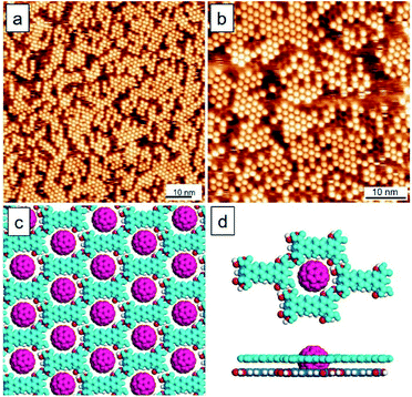
Having established the linear quasi-crystal, we started to explore a host–guest system involving C60. To produce high-density packing, saturated sample solutions of TPTC and C60 were prepared and mixed before deposition. The flow was applied to the droplet of the sample surface upon drop-casting the mixed sample solution. Fig. 5a and b show the large- and small-scale STM images of the TPTC–templated C60 co-assembly prepared by the flow. Fig. 5c and d display the corresponding top- and side-view models. Due to the height of C60, the STM tunneling conditions used are difficult to visualize the bottom layer of TPTC. We have utilized Fig. S6 in the ESI† to confirm the bilayer TPTC; the bottom layer can be revealed by increasing the tunneling current. Remarkably, the C60 molecules appear in a close packing manner and the linear template of TPTC can be revealed from the STM images. The results are consistent with our proposal that linear packing can assist the formation of close packing C60 arrays. Due to the removal of the solvent by the flow method, the C60 molecules were trapped on the host template and they do not desorb easily. The almost dried surface decreases the dynamics including the desorption of C60 molecules from the template.
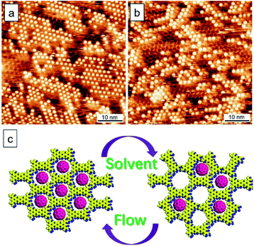
A unique characteristic of the present system is that the TPTC molecules in the random-tiling packing are mobile and thus their rearrangements occur all the time.23 Taking advantage of this, the reversibility can be realized in a controlled fashion. Specifically, the packing density of C60 between low and high in the complex can be readily switched by drop-casting neat solvent (OA) onto the surface and applying the flow to the surface, respectively. Fig. 6a and b show the time-dependent STM monitoring after drop-casting a neat solvent (40 °C) onto a close packing TPTC–C60 surface prepared by the flow. The warm solvent promotes the occurrence of phase transition for the TPTC template from linear to random tiling as revealed by the STM images (within an hour after solvent deposition). The fuzzy features surrounding the C60 dots indicate the fast dynamics of TPTC and C60 at the surface.27,35 Such a characteristic gradually disappeared for the next one hour and the thermodynamically stable packing with low-density C60 accommodated was subsequently obtained (Fig. S7 in the ESI†). Fig. 6c shows a schematic diagram of the reversibility between the linear and porous templates for the accommodation of C60. The conversion between the two types of complexes was controlled by the flow and the solvent drop-casting. The trapping density of C60 into the porous and linear templates was calculated to be 8.7 and 45.5 (these values represent the number of C60) per 100 nm2. The kinetic flow-induced co-assembly presents a better efficiency for trapping C60 (ca. 6 times) compared with that obtained with the entropy-control random-tiling template.
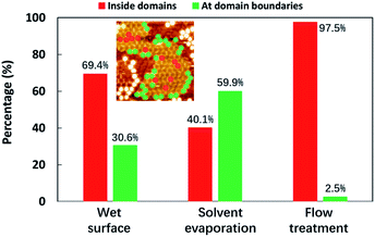
For comparison, Fig. 7 shows the histogram of the positions where C60 molecules were trapped for the cases of the wet surface (the normal liquid–solid interface), the dried surfaces formed by spontaneous solvent evaporation, and the flow-treatment surface.
These statistics were obtained from three 120 × 120 nm2 scanning areas (described in detail in Fig. S8, S9, and Table S3†), showing the trapping positions at the domain boundaries or inside domains. We defined the percentage of the C60 molecules that are confined inside the domains as “confining efficiency”. Significantly, at the normal liquid–solid interface, the C60 molecules preferred to accommodate themselves inside the domains, which shows a confining efficiency of 69.4%. However, after the solvent evaporated gradually, the majority of the guest C60 molecules were trapped at the domain boundaries, with an unsatisfactory confining efficiency of 40.1%. The highly mobile guest molecules prefer the adsorption position of grain boundaries, reminiscent of the C60-TMA (trimesic acid) case. It has been reported that C60 molecules tend to stay in the domain boundaries of the chicken-wire networks of TMA and thus do not prefer to form co-crystals although the TMA pore size matches very well with that of C60.36 Such a dried surface cannot be good for use in related devices. Nevertheless, in our flow-treatment scenario, the C60 molecules were not only trapped in the template with high density but also stabilized inside the domains, with a great confining efficiency which is up to 97.5%. The arrangement of stabilized C60 has a preferred direction within the linear network with stripes running along the lamellae direction, which can be ascribed to solvent dewetting (slip-stick motion of solvent) that plays a role in determining the resulting C60 adsorption as well. In a nutshell, C60 molecules tend to stay in the domain boundaries of the random-tiling template, which however can be circumvented by the linear template generated via the flow.
Finally, some aspects and notes were discussed to comprehend this work. (1) The TPTC–C60 mixing was performed before being subjected to the flow treatment that enabled the removal of solvent and thus led to enhanced stability of the hybrid thin films. The extremely low adsorption ability of C60 onto HOPG results in the process where a linear TPTC pattern is formed followed by the subsequent adsorption of C60. In the present case, we take advantage of the spontaneous rearrangement of TPTC molecules in a random-tiling manner. The flow stimulation applied to the surface can easily trigger the phase transition from glass-like to linear packing and in turn produce close packing C60 arrays in the host–guest complex. (2) The occurrence of close packing C60 arrays only depends on the template underneath. The efficiency of the close packing of C60 can be hugely hampered by the glass-like template. Therefore, it is important to switch as much as possible the surface percentage from random tiling TPTC to linear packing. Note that the volume of the sample solution is crucial. A liquid droplet needs at least 10 μL to afford an efficient flow rate to drive the phase transformation of TPTC. (3) Also note that the high concentration of TPTC is important for the present study, which forces TPTC adsorption onto the surface and thus the formation of a second layer. Based on STM investigations, the TPTC monolayers with either random tiling or linear packing seem to bear a low ability for trapping C60. Occasionally, STM visualizes the dynamics where the second layer appears first followed by C60 adsorption. This suggests that the guest molecules have less ability to affect the formation of the TPTC bilayer although their adsorption, to some degree, may contribute stabilizing energy to the complex. (4) Due to tunneling parameters, the STM tip which is far away from the surface thus can usually visualize the upper layer TPTC. The first layer of TPTC can be revealed by increasing the tunneling current (Fig. S6†), which confirms bilayer templates. (5) Regarding stability, when solvent liquid exists on the surface, the linear template cannot survive for a long time. They can collapse and transition to random tiling and thus result in low-density C60 adsorption, which is the thermodynamically and entropically preferred state in the system. Therefore, the complete removal of the solvent via the unique flow method plays a silent yet essential role in the present study. In other words, less solvent was left on the surface, and the phase transition took place at a lower speed and vice versa.37 Such prepared thin films can be stabilized for at least 24 hours under ambient conditions. (6) Last but not least, it is worthwhile to emphasize that the flow can affect the template with an mm level range and thus produce close packing C60 over an mm scale; Fig. S5† exhibits such investigations. This may enhance the out-of-plane electron transfer efficiency in the so-called sandwich devices that are in contrast to OFETs (e.g., in-plane electron transport).38 In short, the key to success in enabling closely packed C60 molecule accommodation is to create and further stabilize the linear quasi-crystal against the spontaneous occurrence of random tilling. The flow-based tackle used for the host–guest supramolecular system has been unprecedented to date.
Conclusions
In conclusion, we have reported a flow method for tailoring the template packing of TPTC for yielding close packing guest accommodation over the HOPG surface with an mm-level scale. Our STM data unambiguously show that a solvent flow driven by capillary force can induce the packing transition from a glass-like assembly to a linear quasi-crystal which can further trap C60 producing close packing guest arrays. This would otherwise display low-density adsorption in the TPTC–C60 complex at the liquid–solid interface. After the flow treatment, the total number of C60 molecules is increased apparently, and the accommodation efficiency is largely improved compared to that of the spontaneous solvent evaporation case (from 40.1% to 97.5%). The high-density packing of C60 was stabilized, ascribed to the removal of the solvent in our method, which may benefit further applications in sensing or molecular-based electronics, e.g., sandwich optoelectronic devices that need high-density molecular arrays and out-of-plane electron transport. Such host-guest complexes can be switched reversibly by the flow and solvent drop-casting via tailoring the template underneath. Overall, this study represents a conceptual advance in the sample-preparation process for tailoring the host–guest supramolecular system towards desired surfaces and potential applications.Conflicts of interest
There are no conflicts to declare.Acknowledgements
The authors thank NSFC (21972095), Shenzhen University, Guangdong government (2018A030313467), Shenzhen City: 1. The overseas talent setup funding; 2. JCYJ20180305124732178; 3. JCYJ20190808151815169; 4. RCBS20210609103228020.References
- Z.-G. Wang and B. Ding, Acc. Chem. Res., 2014, 47, 1654–1662 CrossRef CAS PubMed.
- S. B. Khan and S.-L. Lee, Molecules, 2021, 26, 3995 CrossRef CAS PubMed.
- S. Stepanow, M. Lingenfelder, A. Dmitriev, H. Spillmann, E. Delvigne, N. Lin, X. Deng, C. Cai, J. V. Barth and K. Kern, Nat. Mater., 2004, 3, 229–233 CrossRef CAS PubMed.
- D. P. Goronzy, M. Ebrahimi, F. Rosei, Arramel, Y. Fang, S. De Feyter, S. L. Tait, C. Wang, P. H. Beton, A. T. S. Wee, P. S. Weiss and D. F. Perepichka, ACS Nano, 2018, 12, 7445–7481 CrossRef CAS PubMed.
- C. Wang, H. Dong, W. Hu, Y. Liu and D. Zhu, Chem. Rev., 2011, 112, 2208–2267 CrossRef PubMed.
- S.-L. Lee, J. Adisoejoso, Y. Fang, K. Tahara, Y. Tobe, K. S. Mali and S. De Feyter, Nanoscale, 2015, 7, 5344–5349 RSC.
- S. Uemura, R. Tanoue, N. Yilmaz, A. Ohira and M. Kunitake, Materials, 2010, 3, 4252–4276 CrossRef CAS PubMed.
- D. Rohde, C. J. Yan, H. J. Yan and L. J. Wan, Angew. Chem., Int. Ed., 2006, 45, 3996–4000 CrossRef CAS PubMed.
- Q. N. Zheng, X. H. Liu, X. R. Liu, T. Chen, H. J. Yan, Y. W. Zhong, D. Wang and L. J. Wan, Angew. Chem., Int. Ed., 2014, 53, 13395–13399 CrossRef CAS PubMed.
- S. B. Lei, K. Deng, Y. L. Yang, Q. D. Zeng, C. Wang and J. Z. Jiang, Nano Lett., 2008, 8, 1836–1843 CrossRef CAS PubMed.
- Y. T. Shen, L. Guan, X. Y. Zhu, Q. D. Zeng and C. Wang, J. Am. Chem. Soc., 2009, 131, 6174–6180 CrossRef CAS PubMed.
- Y. T. Shen, K. Deng, X. M. Zhang, W. Feng, Q. D. Zeng, C. Wang and J. R. Gong, Nano Lett., 2011, 11, 3245–3250 CrossRef CAS PubMed.
- S.-L. Lee, Y. J. Hsu, H. J. Wu, H. A. Lin, H. F. Hsu and C. H. Chen, Chem. Commun., 2012, 48, 11748–11750 RSC.
- S.-L. Lee, C. H. Lin, K. Y. Cheng, Y. C. Chen and C. H. Chen, J. Phys. Chem. C, 2016, 120, 25505–25510 CrossRef CAS.
- J. Teyssandier, S. De Feyter and K. S. Mali, Chem. Commun., 2016, 52, 11465–11487 RSC.
- D. S. Deak, F. Silly, K. Porfyrakis and M. R. Castell, Nanotechnology, 2007, 18, 075301 CrossRef PubMed.
- J. D. Cojal González, M. Iyoda and J. P. Rabe, Nat. Commun., 2017, 8, 14717 CrossRef PubMed.
- E. Mena-Osteritz and P. Bäuerle, Adv. Mater., 2006, 18, 447–451 CrossRef CAS.
- L. Piot, F. Silly, L. Tortech, Y. Nicolas, P. Blanchard, J. Roncali and D. Fichou, J. Am. Chem. Soc., 2009, 131, 12864–12865 CrossRef CAS PubMed.
- M. Li, K. Deng, S. B. Lei, Y. L. Yang, T. S. Wang, Y. T. Shen, C. R. Wang, Q. D. Zeng and C. Wang, Angew. Chem., Int. Ed., 2008, 47, 6717–6721 CrossRef CAS PubMed.
- X. Zeng, A. Mahmood, J. Guo, Y. Hu, Y. Chan and S.-L. Lee, J. Phys. Chem. C, 2020, 124, 22521–22528 CrossRef CAS.
- M. O. Blunt, J. C. Russell, C. Gimenez-Lopez Mdel, N. Taleb, X. Lin, M. Schroder, N. R. Champness and P. H. Beton, Nat. Chem., 2011, 3, 74–78 CrossRef CAS PubMed.
- M. O. Blunt, J. C. Russell, C. Gimenez-Lopez Mdel, J. P. Garrahan, X. Lin, M. Schroder, N. R. Champness and P. H. Beton, Science, 2008, 322, 1077–1081 CrossRef CAS PubMed.
- J. A. A. W. Elemans, Adv. Funct. Mater., 2016, 26, 8932–8951 CrossRef CAS.
- S.-L. Lee, C.-Y. J. Chi, M.-J. Huang, C.-H. Chen, C.-W. Li, K. Pati and R.-S. Liu, J. Am. Chem. Soc., 2008, 130, 10454–10455 CrossRef CAS PubMed.
- D.-D. Zhou, J. Wang, P. Chen, Y. He, J.-X. Wu, S. Gao, Z. Zhong, Y. Du, D. Zhong and J.-P. Zhang, Chem. Sci., 2021, 12, 1272–1277 RSC.
- X. Zeng, S. B. Khan, A. Mahmood and S.-L. Lee, Nanoscale, 2020, 12, 15072–15080 RSC.
- R. Steeno, A. Minoia, M. C. Gimenez-Lopez, M. O. Blunt, N. R. Champness, R. Lazzaroni, K. S. Mali and S. De Feyter, Chem. Commun., 2021, 57, 1454–1457 RSC.
- P. Lei, L. Zhao, L. He, F. Zhao, X. Xiao, B. Tu and Q. Zeng, Appl. Surf. Sci., 2021, 550, 149352 CrossRef CAS.
- A. Mahmood, M. Saeed, Y. Chan, A. S. Saleemi, J. Guo and S.-L. Lee, Langmuir, 2019, 35, 8031–8037 CrossRef CAS PubMed.
- S.-L. Lee, Z. Yuan, L. Chen, K. S. Mali, K. Mullen and S. De Feyter, J. Am. Chem. Soc., 2014, 136, 4117–4120 CrossRef CAS PubMed.
- S.-L. Lee, Z. Yuan, L. Chen, K. S. Mali, K. Mullen and S. De Feyter, J. Am. Chem. Soc., 2014, 136, 7595–7598 CrossRef CAS PubMed.
- K. Miao, Y. Hu, B. Zha, L. Xu, X. R. Miao and W. L. Deng, J. Phys. Chem. C, 2016, 120, 14187–14197 CrossRef CAS.
- X. Zeng, Y. Hu, R. Xie, S. B. Khan and S.-L. Lee, Molecules, 2021, 26, 7707 CrossRef CAS PubMed.
- E. Ghijsens, H. Cao, A. Noguchi, O. Ivasenko, Y. Fang, K. Tahara, Y. Tobe and S. De Feyter, Chem. Commun., 2015, 51, 4766–4769 RSC.
- D. den Boer, G. D. Han and T. M. Swager, Langmuir, 2014, 30, 762–767 CrossRef CAS PubMed.
- S.-L. Lee, Y. Fang, G. Velpula, F. P. Cometto, M. Lingenfelder, K. Mullen, K. S. Mali and S. De Feyter, ACS Nano, 2015, 9, 11608–11617 CrossRef CAS PubMed.
- F.-J. Lin, C.-W. Yang, H.-H. Chen and Y.-T. Tao, J. Am. Chem. Soc., 2020, 142, 11763–11771 CrossRef CAS PubMed.
Footnotes |
| † Electronic supplementary information (ESI) available. See https://doi.org/10.1039/d2na00160h |
| ‡ These authors contributed equally to this work. |
| This journal is © The Royal Society of Chemistry 2022 |

