 Open Access Article
Photothermal synthesis of a CuOx&FeOy catalyst with a layered double hydroxide-derived pore-confined frame to achieve photothermal CO2 hydrogenation to CO with a rate of 136 mmol min−1 gcat−1†
Lizhu
Song
a,
Xinli
Yi
a,
Shuxin
Ouyang
 *b and
Jinhua
Ye
 ac
ac
aTJU-NIMS International Collaboration Laboratory, School of Materials Science and Engineering, Tianjin University, Tianjin 300072, P. R. China
bKey Laboratory of Pesticide and Chemical Biology, Ministry of Education, College of Chemistry, Central China Normal University, Wuhan 430079, P. R. China. E-mail: oysx@mail.ccnu.edu.cn
cInternational Center for Materials Nanoarchitectonics (WPI-MANA), National Institute for Materials Science (NIMS), 1-1 Namiki, Tsukuba 305-0047, Japan
First published on 12th July 2022
Abstract
Solar-driven CO2 conversion into the industrial chemical CO via the reverse water–gas reaction is an ideal technological approach to achieve the key step of carbon neutralization. The high reaction temperature is cost-free due to the photothermal conversion brought about by solar irradiation and is beneficial to the catalytic efficiency. However, the thermostability of adopted catalysts is a great challenge. Herein, we develop an in situ photothermal synthesis to obtain a CuOx&FeOy catalyst with a layered double hydroxide-derived pore-confined frame. The optimized sample delivers a CO generation rate of 136.3 mmol min−1 gcat−1 with the selectivity of ∼100% at a high reaction temperature of 1015 °C. The efficient catalytic activity can be attributed to the fact that the pore-confined frame substrate prevents the growth of CuOx and FeOy nanoparticles during the high-temperature reaction and the basic groups on the substrate promote the adsorption and activation of CO2.
Introduction
Carbon dioxide (CO2), a typical greenhouse gas, has a significant impact on the climate of the earth, and carbon neutralization consumes huge amounts of energy due to the inertness of CO2.1 Nowadays, profiting from photothermocatalysis driven by sunlight, the catalytic conversion of CO2 into various value-added chemicals (alkanes, alcohols, and other multi-carbon organics) via the photothermal reverse water–gas shift (RWGS) reaction (CO2 + H2 ↔ CO + H2O)2,3 followed by Fischer–Tropsch synthesis (FTS: nCO + 2nH2 → CnH2n + nH2O)4 is a feasible and almost energy cost-free “two-step” approach for carbon recycling.2,5 However, the high yield rate and near-unity selectivity of CO during the photothermal RWGS reaction step is still a challenge so that the ratio of the feedstock gases (syngas, CO and H2) for the subsequent Fischer–Tropsch synthesis can be facilely tuned and rapidly imported.6Cu-based catalysts stand out among the various high CO-selective catalysts because of their abundant resources and low price.7 As summarized in Table 1, the CO selectivity of Cu-based catalyst is close to 100%.8–11 Hydrocarbons such as CH4 are nearly impossible to form,7,12 even under H2-rich conditions (H2 > 99 vol%).13 The RWGS reaction is mildly endothermic ( = 42.1 kJ mol−1),3 and a higher reaction temperature is beneficial for promoting the catalytic efficiency.14 However, Cu-based catalysts exhibit poor thermostability, which makes them prone to sintering aggregation during the high-temperature RWGS reaction, since the Tammann temperature of Cu films is low (∼930 K, satisfying the general trend that the Tammann temperature is normally about 2/3 of a material's melting temperature).15 In addition, photothermal catalysts with other metal elements as active components, such as 2D Black In2O3−x,16 C–In2O3−x,17 Co@CoN&C,18 and Fe@C,19 are still suitable for low-temperature photothermal catalysis.20 Therefore, achieving the thermostability of adopted catalysts for the high-temperature photothermal RWGS reaction is a great challenge.
| Catalyst | Preparation | Reaction tem. (°C) | CO rate (mmol min−1 gcat−1) | CO2 con. (%) | CO sel. (%) | Ref. |
|---|---|---|---|---|---|---|
| a The synthesis of the catalyst did not undergo any thermal reduction process. b P.T.: photothermal. | ||||||
| Thermal catalysis | ||||||
| 10%Cu5%Fe/CeO2 | 900–1000 °C | 650 | 0.4 | 42 | 100 | 8 |
| 400 °C, 4 h | ||||||
| 0.3CuMgAl-LDH | 500 °C, ∼ | 350 | 0.2 | 32.9 | 99.8 | 9 |
| CuO/ZnO/Al2O3 | 400 °C, 8 h | 250 | 17 | 10 | ||
| Cu–Fe/SiO2 | 600 °C, 5 h | 600 | 15 | 11 | ||
![[thin space (1/6-em)]](https://www.rsc.org/images/entities/char_2009.gif) |
||||||
| Photothermal catalysis | ||||||
| 2D Black In2O3−x | 150 °C, 2 h | 340 | 1.7 | 53.3 | 100 | 16 |
| C–In2O3−x | 600 °C, 4 h | 400 | 2.1 | 45 | 100 | 17 |
| Co@CoN&C | 550 °C, 4 h | 518 | 2.2 | 41.3 | 91.1 | 18 |
| Fe@C | 500 °C, 2 h | 481 | 0.4 | 99.7 | 19 | |
| 700 °C, 2 h | ||||||
| CuOx&FeOy/MAO | ∼a | 1015 (P.T.)b | 136.3 | 45.6 | 100 | This study |
The widely adopted modifications to enhance the thermostability of catalysts, such as adding precious metals21–24 or constructing core/shell structures,25,26 are expensive or/and involve complex synthesis, which are difficult to apply in industry. Herein, we demonstrate an in situ photothermal synthesis to obtain a CuOx&FeOy catalyst with a layered double hydroxide-derived pore-confined frame, which prevents the growth of CuOx and FeOy nanoparticles during the high-temperature reaction, and the basic groups on the catalyst promote the adsorption and activation of CO2. Under focused sunlight irradiation simulated by a Xe lamp, the RWGS reaction can proceed over the CuOx&FeOy/MAO catalyst at a high temperature of 1015 °C to deliver a stable CO yield rate of 136.3 mmol min−1 gcat−1 and a near 100% selectivity for 10 hours. The apparent activity of CuOx&FeOy/MAO remarkably surpasses that of the representative catalysts in thermocatalysis or photothermocatalysis, as listed in Table 1.
Results and discussion
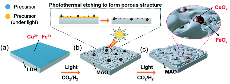
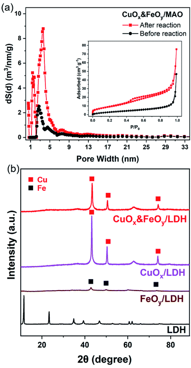
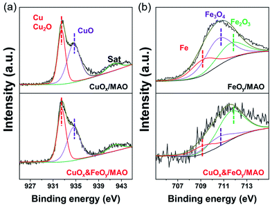
The pre-catalyst was prepared via an impregnation method with Cu(NO3)2·3H2O, Fe(NO3)3·9H2O and commercial Mg6Al2(CO3)(OH)16·4H2O (Mg,Al-LDH) as raw materials. Then, the pre-catalyst was photothermally treated in a flow-type reactor (Fig. S1, ESI†) under the RWGS reaction atmosphere to obtain the final catalyst (denoted as CuOx&FeOy/MAO). The proposed formation mechanism of the Mg,Al-LDH derivative-confined CuOx&FeOy catalyst is presented in Scheme 1. Under a rising temperature via light-to-heat conversion and an atmosphere of CO2 and H2, the loaded Cu2+ and Fe3+ in the impregnation process (Scheme 1a) were reduced to Cu and Fe NPs, respectively (Scheme 1b). Due to the generation of H2O, the surface of the nano-metals was partially oxidized to their respective oxides (Cu2O and Fe3O4). The localized photothermal effect of the nano-metals led to a phase transformation of the hydroxide into amorphous phase oxides (MgO and Al2O3, MAO), causing a thermal etching effect and forming a porous structure at the surface (inset of Scheme 1b), which can be evidenced by the measurements of the BET surface area and pore-structure analysis (Table S1† and Fig. 1a). These surface pores confine the growth of CuOx and FeOy. Due to the different growth rates, some ultrafine FeOy NPs locate around CuOx (Scheme 1c), which stabilizes the size and chemical valence of CuOx (which will be discussed in a later section in detail). The high-melting-point materials of MgO and Al2O3 construct a high-temperature-stable substrate, which plays an important role in reinforcing the stability of the newly formed porous structure.X-ray diffraction (XRD) and X-ray photoelectron spectroscopy (XPS) were adopted to determine the phase compositions and the chemical valence of the elements in the samples before and after the reaction. After the photothermocatalytic RWGS reaction, the XRD patterns of CuOx&FeOy/MAO (Fig. 1b) mainly present the characteristic peaks of metallic Cu, while the two peaks near 38° and 62° cannot be assigned to a specific phase. According to the XPS results (Fig. 2), the peaks at the binding energies of 932.5, 934.6 and 941.8 eV are related to the Cu and Cu2O, CuO, and satellite peaks, respectively.12,27 Three peaks were observed at 709.4, 710.4, and 711.6 eV, which can be assigned to metallic Fe, Fe3O4, and Fe2O3, respectively. Therefore, the Cu- and Fe-related compositions in the catalyst are designated as CuOx and FeOy, respectively. The possible phase compositions related to the Mg and Al elements are partially crystallized or amorphous MgO and Al2O3, as previously reported,28 and therefore, the substrate is denoted as MAO.
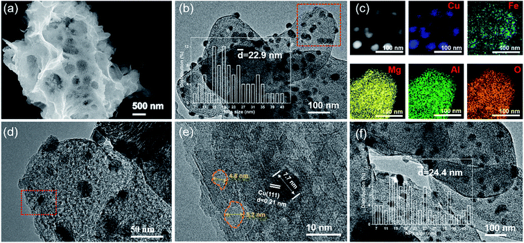
As shown in Fig. S2 (ESI†), the commercial Mg,Al-LDH features a smooth and flat sheet morphology. However, the SEM image of CuOx&FeOy/MAO after a 10 h photothermal RWGS reaction (Fig. 3a) indicates a complex pore structure on the surface of the catalyst substrate. In the TEM and high-resolution TEM (HRTEM) images (Fig. 3b, d and e), the dark sphere-like particles can be identified as metallic Cu according to the 0.21 nm lattice fringes associated with the Cu(111) crystal plane; therefore, a certain number of these Cu nanoparticles (NPs) were selected to survey their size and their average diameter is 22.9 nm (inset of Fig. 3b). Moreover, the pore structures on the substrate surface can be clearly observed due to the shallow contrast, and their sizes mainly distribute around 5 nm (Fig. 3e). Elemental mapping of CuOx&FeOy/MAO (Fig. 3c) revealed that the Cu element distribution is highly concentrated, which is well consistent with the bright spots of the HAADF-TEM image. The Fe element presents a relatively aggregated distribution around Cu, and thus, the XRD patterns exhibit that the Cu composition is crystallized, while the featured peaks of Fe cannot be observed. Based on the calculation of the overlapping colorful regions in the elemental mapping of Cu and Fe, it can be estimated that about 40.9% of the Fe NPs are in close contact with Cu NPs. The Mg, Al, and O elements are uniformly dispersed, suggesting that they are the main components of the substrate. These results are well consistent with the characterization results of XRD. Thus, the above characterizations reveal the formation of the well-dispersed active phase on the porous-structured substrate. The Fe-free catalyst SEM and TEM images demonstrate the significant agglomeration of metallic Cu NPs, as can be seen in Fig. S3 (ESI†).
Photothermal catalysts require a wide wavelength region of light absorption to attain efficient light-to-heat conversion. The UV-visible absorption spectra of the catalysts after the RWGS reaction are shown in Fig. S4 (ESI†). It can be observed that CuOx&FeOy/MAO and the two reference catalysts of CuOx&FeOy/MgO and CuOx&FeOy/Al2O3 exhibit intense light absorption in the UV and visible regions. In general, the substrate affects the light absorption property of the catalyst, and the MAO substrate with pores strongly promotes the absorption intensity of the catalyst, which might be attributed to multi-light reflections by the porous surface. Accordingly, the light-to-heat conversion efficiency of CuOx&FeOy/MAO is higher than that of the other two catalysts. Its equilibrium temperature is as high as 1015 °C, which is 40 °C and 56 °C higher than that of the other two catalysts, respectively (Fig. S5, ESI†).
To verify that CuOx&FeOy/MAO can prevent sintering aggregation, the photothermal catalysis of the reverse water–gas shift (RWGS) reaction over the as-prepared catalysts was carried out in a flow-type reaction system at a working temperature higher than 950 °C. As presented in Fig. 4a, the average CO yield rate of CuOx&FeOy/MAO is 136.3 mmol min−1 gcat−1 with a selectivity of ∼100% and an average CO2 conversion of 41.3% during 10 h light irradiation. The various active phases (CuOx or FeOy) and substrates (MgO or Al2O3) were substituted in the mixture of CuOx and FeOy and MAO to explore their roles in enhancing the catalytic activity and stability (Fig. 4a). The key findings can be summarized as follows. First, while adopting the same substrate of MAO, the catalytic activity order is CuOx&FeOy/MAO > CuOx/MAO > FeOy/MAO and the activity of CuOx&FeOy/MAO (136.3 mmol min−1 gcat−1) is even higher than the sum (86.3 + 41.9 mmol min−1 gcat−1) of the activities of the two latter catalysts, indicating that the composite of CuOx and FeOy is a superior active phase. Second, the CO evolution rates over CuOx&FeOy/MAO and FeOy/MAO exhibit good sustainability. In comparison, the CO yield rates over CuOx&FeOy/Al2O3, CuOx&FeOy/MgO, CuOx/MAO, and FeOy/MAO have fallen by roughly 21.4%, 27.8%, 31.0%, and 12.1%, respectively, after the initial 10 h reaction. The Fe-free catalyst of CuOx/MAO suffers from the most serious deactivation, indicating that FeOy plays a role in promoting the activity stability.29,30 To confirm the excellent stability of CuOx&FeOy/MAO at high reaction temperatures, a long-term stability test (40 h) was conducted (Fig. 4b). The average CO yield rate was 124.9 mmol min−1 gcat−1 during continuous 40 h testing; after the long-term stability test, the average size of the Cu NPs is 24.4 nm (Fig. 3f), which is comparable to that before the reaction (22.9 nm), indicating that the confined frame of MAO and FeOy indeed prevent the sintering aggregation of the Cu NPs. Compared with the stable CuOx&FeOy/MAO catalyst, SEM and TEM indicate obvious agglomeration of the catalysts with Al2O3 (Fig. S6, ESI†) or MgO (Fig. S7, ESI†) as substrates after the 10 h photothermal RWGS reaction, which may be the primary reason for the decrease in catalytic activity. The XRD patterns of the two samples are shown in Fig. S8, ESI.† Moreover, a contrast experiment was carried out to prove the necessity of the localized photothermal effect of the nano-metals to form the porous structure of the MAO substrate, which confined the growth of the nano-metals. The contrast sample was prepared by thermal reduction of the pre-catalyst powder in a tube furnace at 1015 °C for 2 h under a H2/Ar (10 v%/90 v%) atmosphere and labeled as T-CuOx&FeOy/MAO. The XRD patterns (Fig. S9, ESI†) indicate that the catalyst carrier was composed of MgAl2O4 and MgO. The specific surface area of T-CuOx&FeOy/MAO (110.8 m2 g−1) exceeded three times that of CuOx&FeOy/MAO after reaction (Fig. S10, ESI†). However, the CO production rate was 91.4 mmol min−1 gcat−1, in conjunction with a downward trend of activity in the first 2 hours (Fig. S11, ESI†). The SEM and TEM images of T-CuOx&FeOy/MAO after the photothermal RWGS reaction show a significant agglomeration of metallic Cu NPs (Fig. S12, ESI†).
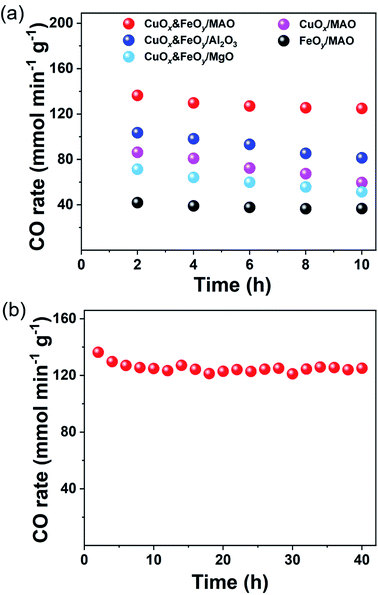 | ||
| Fig. 4 Photothermal RWGS reaction tests. (a) CO yield rate. (b) Long-term stability testing over CuOx&FeOy/MAO. | ||
The Fourier transform infrared (FT-IR) spectra were recorded to explore the CO2 conversion over the surface of the catalysts. The results were analyzed by referring to previous literature.31 Compared with the fresh LDH carrier (Fig. S13, ESI†), the FT-IR spectra of the spent CuOx&FeOy/MAO catalyst (Fig. S14, ESI†) indicate the conversion of absorbed CO2 into the easily activated form of carbonate/bicarbonate (CO32−/HCO3−). CO32−/HCO3− was reduced to formate species by the dissociation of H on Cu NPs. CO32−/HCO3− bands were observed at 880 cm−1 [IV] and 1448 cm−1 [II, ν(OCO)s]. The CuOx&FeOy/MAO catalyst showed the strongest absorption band at 1448 cm−1, indicating that it possesses an abundance of HCO3−, which is easier to convert into formate species than CO32−. The high-temperature stabilization of bridge formate (br-HCOO) on the catalyst surface was detected at 1635 cm−1 [I, asymmetrical, ν(OCO)as] and 1384 cm−1 [III, symmetrical, ν(OCO)s]. The generated formate species further decomposed into CO and regenerated OH−.32
The mechanism of the Mg,Al-LDH-derived MAO frame-confined CuOx&FeOy catalyst with efficient and stable catalytic performance under high temperature can be summarized as follows. Since Cu NPs are the active phase, the microstructure feature and the chemical environment around them affect the catalytic performance (Fig. 5). Fe-based materials are often applied as promoters to improve the thermal stability and catalytic activity of RWGS catalysts.8,11,30,33–35 Firstly, the Fe-based promoter exhibits much better dispersity than the active phase of Cu (which can be evidenced by the TEM and elemental mapping results of CuOx&FeOy/MAO, Fig. 3). The ultrafine and amorphous FeOy NPs around the crystallized CuOx also protect the CuOx NPs from sintering growth, especially along the surface (Scheme 1b), which promotes the thermal stability significantly. Secondly, the introduction of Fe oxide increased the basic sites of the catalyst and enhanced the adsorption ability of CO2 (Fig. S15, ESI†).11 Moreover, as seen in the XPS results, the Cu 2p3/2 binding energy in CuOx&FeOy/MAO shifted negatively compared to that in CuOx/MAO, suggesting that low-valence Cu was significantly more abundant in the former. This can be attributed to the fact that the Cu-FeOy interfacial region provides more active sites for H2 dissociation than individual Cu and Fe, and therefore transfers active H to Cu, which maintains the low chemical valence of Cu.33,36 This can be supported by the fact that the introduction of excessive Fe results in the formation of CH4 (Fig. S16, ESI†). The amorphous MAO substrate derived from Mg,Al-LDH possesses abundant surface basic groups, which facilitate the chemical adsorption, activation and conversion of CO2; the relevant processes are shown as chemical equations in Fig. 5b.37 The basic active sites over the CuOx&FeOy/MAO catalyst feature cyclic regeneration, which can be evidenced by the FT-IR spectra after the photothermal reaction (Fig. S14, ESI†). Besides, according to our reported method,12 contrast activity evaluations under light irradiation with or without UV light were carried out; the performance exhibits a slight reduction in the absence of UV light, indicating a coupling effect of photothermocatalysis and photocatalysis (Fig. S17, ESI†).
Conclusions
In summary, a CuOx&FeOy catalyst with an LDH-derived pore-confined frame was prepared by an in situ photothermal procedure in the RWGS reaction atmosphere. The introduction of an Fe-based promoter stabilized the low chemical valence of Cu in CuOx, leading to excellent RWGS activity. The pore-confined frame consisted of Mg,Al-LDH in the bulk and a mixture of MgO and Al2O3 on the surface, which provided a thermally stable porous structure with abundant basic groups. Besides suppressing the growth of CuOx and FeOy NPs, this unique substrate promoted the adsorption and activation of CO2. The above-mentioned advantages enable CuOx&FeOy/MAO to exhibit durable activity in the RWGS reaction at a photothermally induced high temperature of 1015 °C. The catalyst delivered a CO yield rate of 136.3 mmol min−1 gcat−1 with near-unity selectivity. Our study provides a facile and cost-efficient method to prepare high-temperature-capable catalysts, which extends the solar-driven photothermocatalysis application to the working temperature range of 1000 °C.Experimental section
The experimental details are provided in the ESI.†Author contributions
Lizhu Song and Shuxin Ouyang conceived the study. Lizhu Song and Xinli Yi performed the experiments and carried out the material characterization. Lizhu Song, Xinli Yi, Shuxin Ouyang and Jinhua Ye analyzed the results and wrote the manuscript. All authors participated in the discussion and interpretation of the results.Conflicts of interest
There are no conflicts to declare.Acknowledgements
This work received financial support from the National Natural Science Foundation of China (Grant Number 21972052) and JSPS KAKENHI of Japan (Grant Number JP18H02065).Notes and references
- Y. Xu, P. N. Duchesne, L. Wang, A. Tavasoli, A. A. Jelle, M. Xia, J. Liao, D. Kuang and G. A. Ozin, Nat. Commun., 2020, 11, 5149 CrossRef CAS PubMed.
- Y. Ma, Z. Guo, Q. Jiang, K. Wu, H. Gong and Y. Liu, J. Energy Chem., 2020, 50, 37–43 CrossRef.
- Y. A. Daza and J. N. Kuhn, RSC Adv., 2016, 6, 49675–49691 RSC.
- F. Jiao, J. Li, X. Pan, J. Xiao, H. Li, H. Ma, M. Wei, Y. Pan, Z. Zhou, M. Li, S. Miao, J. Li, Y. Zhu, D. Xiao, T. He, J. Yang, F. Qi, Q. Fu and X. Bao, Science, 2016, 351, 1065–1068 CrossRef CAS PubMed.
- M. Wang, M. Shen, X. Jin, J. Tian, M. Li, Y. Zhou, L. Zhang, Y. Li and J. Shi, ACS Catal., 2019, 9, 4573–4581 CrossRef CAS.
- J. Li, Y. He, L. Tan, P. Zhang, X. Peng, A. Oruganti, G. Yang, H. Abe, Y. Wang and N. Tsubaki, Nat. Catal., 2018, 1, 787–793 CrossRef CAS.
- F. Liu, L. Song, S. Ouyang and H. Xu, Catal. Sci. Technol., 2019, 9, 2125–2131 RSC.
- L. Chen, D. Wu, C. Wang, M. Ji and Z. Wu, J. Environ. Chem. Eng., 2021, 9, 105183 CrossRef CAS.
- Y. Chen, H. Hong, J. Cai and Z. Li, ChemCatChem, 2021, 13, 656–663 CrossRef CAS.
- M. J. L. Ginés, A. J. Marchi and C. R. Apesteguía, Appl. Catal., A, 1997, 154, 155–171 CrossRef.
- M. González-Castano, J. C. Navarro de Miguel, F. Sinha, S. Ghomsi Wabo, O. Klepel and H. Arellano-Garcia, J. CO2 Util., 2021, 46, 101493 CrossRef.
- L. Zhao, Y. Qi, L. Song, S. Ning, S. Ouyang, H. Xu and J. Ye, Angew. Chem., Int. Ed., 2019, 58, 7708–7712 CrossRef CAS PubMed.
- Y. Tong, L. Song, S. Ning, S. Ouyang and J. Ye, Appl. Catal., B, 2021, 298, 120551 CrossRef CAS.
- X. Su, X. Yang, B. Zhao and Y. Huang, J. Energy Chem., 2017, 26, 854–867 CrossRef.
- G. Mahmud, H. Zhang and J. F. Douglas, J. Chem. Phys., 2020, 153, 124508 CrossRef CAS PubMed.
- Y. Qi, L. Song, S. Ouyang, X. Liang, S. Ning, Q. Zhang and J. Ye, Adv. Mater., 2020, 32, 1903915 CrossRef CAS PubMed.
- Y. Qi, J. Jiang, X. Liang, S. Ouyang, W. Mi, S. Ning, L. Zhao and J. Ye, Adv. Funct. Mater., 2021, 31, 2100908 CrossRef CAS.
- S. Ning, H. Xu, Y. Qi, L. Song, Q. Zhang, S. Ouyang and J. Ye, ACS Catal., 2020, 10, 4726–4736 CrossRef CAS.
- H. Zhang, T. Wang, J. Wang, H. Liu, T. D. Dao, M. Li, G. Liu, X. Meng, K. Chang, L. Shi, T. Nagao and J. Ye, Adv. Mater., 2016, 28, 3703–3710 CrossRef CAS PubMed.
- X. Zhu, J. Liu, X. Li, J. Liu, X. Qu and A. Zhu, J. Energy Chem., 2017, 26, 488–493 CrossRef.
- K. Suzuki, T. Yamaguchi, K. Matsushita, C. Iitsuka, J. Miura, T. Akaogi and H. Ishida, ACS Catal., 2013, 3, 1845–1849 CrossRef CAS.
- G. Ren, Y. Tang, K. Liu, Y. Su, S. Miao, W. Liu, W. Cong, X. Wang, W. Li, J. Li and T. Zhang, Nano Lett., 2018, 18, 6489–6493 CrossRef CAS PubMed.
- B. Puértolas, Á. Mayoral, R. Arenal, B. Solsona, A. Moragues, S. Murcia-Mascaros, P. Amorós, A. B. Hungría, S. H. Taylor and T. García, ACS Catal., 2015, 5, 1078–1086 CrossRef.
- C. Moreno, N. J. Divins, J. Gázquez, M. Varela, I. Angurell and J. Llorca, Nanoscale, 2012, 4, 2278–2280 RSC.
- R. Jin, J. Easa and C. P. O'Brien, ACS Appl. Mater. Interfaces, 2021, 13, 38213–38220 CrossRef CAS PubMed.
- D. Lou, Z. Zhu, Y.-F. Xu, C. Li, K. Feng, D. Zhang, K. Lv, Z. Wu, C. Zhang, G. A. Ozin, L. He and X. Zhang, Sci. China Mater., 2021, 64, 2212–2220 CrossRef CAS.
- Z. Zhang, S.-S. Wang, R. Song, T. Cao, L. Luo, X. Chen, Y. Gao, J. Lu, W.-X. Li and W. Huang, Nat. Commun., 2017, 8, 488 CrossRef PubMed.
- U. Sharma, B. Tyagi and R. V. Jasra, Ind. Eng. Chem. Res., 2008, 47, 9588–9595 CrossRef CAS.
- J. Liu, A. Zhang, X. Jiang, M. Liu, Y. Sun, C. Song and X. Guo, ACS Sustainable Chem. Eng., 2018, 6, 10182–10190 CrossRef CAS.
- C. Chen, W. Cheng and S. Lin, Appl. Catal., A, 2004, 257, 97–106 CrossRef CAS.
- N. C. Nelson, M.-T. Nguyen, V.-A. Glezakou, R. Rousseau and J. Szanyi, Nat. Catal., 2019, 2, 916–924 CrossRef CAS.
- N. Ishito, K. Hara, K. Nakajima and A. Fukuoka, J. Energy Chem., 2016, 25, 306–310 CrossRef.
- L. Yang, L. Pastor-Pérez, J. J. Villora-Pico, A. Sepúlveda-Escribano, F. Tian, M. Zhu, Y. Han and T. Ramirez Reina, ACS Sustainable Chem. Eng., 2021, 9, 12155–12166 CrossRef CAS.
- C. Chen, W. Cheng and S. Lin, Chem. Commun., 2001, 18, 1770–1771 RSC.
- Q. Zhang, L. Pastor-Pérez, Q. Wang and T. Ramirez Reina, J. Energy Chem., 2022, 66, 635–646 CrossRef.
- M. Zhu, P. Tian, M. E. Ford, J. Chen, J. Xu, Y.-F. Han and I. E. Wachs, ACS Catal., 2020, 10, 7857–7863 CrossRef CAS.
- J. Ren, S. Ouyang, H. Xu, X. Meng, T. Wang, D. Wang and J. Ye, Adv. Energy Mater., 2017, 7, 1601657 CrossRef.
Footnote |
| † Electronic supplementary information (ESI) available. See https://doi.org/10.1039/d2na00315e |
| This journal is © The Royal Society of Chemistry 2022 |

