 Open Access Article
Nano-sulfur confined in a 3D carbon nanotube/graphene network as a free-standing cathode for high-performance Li–S batteries†
Meng
Wei
 *ab,
Huiqin
Zhu
a,
Pengfei
Zhai
a,
Longkun
An
a,
Hengyi
Geng
a,
Song
Xu
*a and
Tao
Zhang
a
aSchool of Materials Science and Engineering, Zhengzhou University of Aeronautics, Zhengzhou 450046, China. E-mail: weimeng1005@zua.edu.cn; songxu@zua.edu.cn
bHenan Key Laboratory of Aeronautical Materials and Application Technology, Collaborative Innovation Center of Aviation Economy Development, Zhengzhou 450015, Henan Province, China
First published on 27th September 2022
Abstract
A free-standing nano-sulfur-based carbon nanotube/graphene (S/CNT/G) film with a conductive interlinked three-dimensional (3D) nanoarchitecture is fabricated via a facile solution-based method. This 3D multidimensional carbon–sulfur network combines three different nanoarchitectures, as follows: zero-dimensional sulfur nanoparticles, one-dimensional carbon nanotubes, and two-dimensional graphene. The CNTs with a one-dimensional structure act as a conductive matrix, and graphene with two-dimensional sheets is intercalated into the CNT scaffold to build a 3D structure, extending in an additional dimension to provide improved restriction for sulfur/polysulfides. Zero-dimensional sulfur nanoparticles are anchored uniformly on the interpenetrative 3D carbon framework to form a free-standing cathode. Moreover, this well-designed S/CNT/G film is flexible, highly conductive, binder free and current collector free. When directly used as a flexible cathode electrode, the synthesized S/CNT/G film delivers both excellent long-term cycling and high-rate performances. A high initial capacity of 948 mA h g−1 is obtained, and subsequently, a reversible discharge capacity of 593 mA h g−1 over 200 cycles is achieved at 0.5C. Even at a high rate of 3C, the S/CNT/G film with a 50 wt% sulfur content still exhibits a discharge capacity of 598 mA h g−1. These results demonstrate the great potential of the S/CNT/G nanocomposite as a flexible and binder-free cathode for high performance Li–S batteries.
Introduction
Lithium–sulfur (Li–S) batteries have attracted wide and intense interest owing to their potential for applications in next-generation high energy storage devices.1,2 Lithium (Li) and sulfur (S) electrodes, with unparalleled theoretical capacities of 3861 and 1672 mA h g−1 individually, can deliver very high gravimetric and volumetric energy densities of 2500 W h kg−1 and 2800 W h L−1, respectively, assuming a complete reaction of lithium and sulfur to form Li2S.3,4 In addition, the sulfur has a high theoretical capacity of 1675 mA h g−1 and it's abundant in nature, low cost, and non-toxic compared to common traditional materials.5,6 Despite these promising advantages, several drawbacks still limit the practical application of lithium–sulfur batteries.7,8 The main suppression factors for commercial lithium–sulfur batteries are as follows: (i) low sulfur utilization due to the ionic and electrical insulation of sulfur and its discharge products (Li2S and Li2S2); (ii) the so-called “shuttle effect”, where polysulfides dissolve into the electrolyte and shuttle between the Li anode and sulfur cathode, thereby resulting in loss in active materials, low coulombic efficiency, and poor cyclability; (iii) the volume of sulfur expands during the lithiation process, which greatly decreases the cycle life of the lithium-sulfur battery.9,10Great efforts have been made to address the issues of lithium-sulfur batteries, and significant progress has been achieved.11,12 The reasonable design and construction carbon material with sulfur is an effective measure to solve the problems of lithium-sulfur batteries. Various sulfur/carbon composites, such as sulfur/graphene (S/G),13,14 sulfur/carbon nanotubes (S/CNTs),15,16 sulfur/microporous carbon,17,18 sulfur/mesoporous carbon,19,20 and sulfur/carbon fibers,21,22 have been prepared, which exhibit a satisfactory effect on the improvement of the conductivity of sulfur and inhibit the “shuttle effect”. Carbon materials with excellent electrical conductivity, a high specific area, and strong adsorption capability can offer a conductive framework that not only enhances the electric contact of sulfur but also effectively retards the dissolving of polysulfides in the electrolyte.
Among various carbon materials, CNTs and graphene have been considered as star materials in the carbon family and used in lithium–sulfur batteries. Both of them have extraordinary properties, such as high electrical conductivity, a high specific area and strong adsorption capability.23,24 Furthermore, CNTs and graphene have robust mechanical properties that can show flexible performance when serving as conductive agents.25 Some successful examples were reported using carbon nanotubes or graphene as sulfur hosts for lithium–sulfur batteries. For example, Li et al.26 have synthesized a freestanding graphene supported MXene@S electrode. The conductive RGO in the cathode ameliorates MXene nanosheet restacking and the lamellar MXene coated sulfur particles disperse uniformly. Yang et al.27 fabricate a heteroatom-doped CNF-CNT/TMS nanostructure, which can achieve a maximized synergistic effect of electron/ion transport, polysulfide entrapment and catalytic conversion. Liu et al.28 fabricated a film composed of CNTs with an ultrathin sulfur nanolayer coating on the surface of the composite through a heating process. Huang et al.29 introduced a freeze-drying method to prepare a free-standing macroporous film that consists of sulfur and reduced graphene oxide. Zhang et al.30 designed and synthesized an interconnected CNT/graphene nanosphere paper as a flexible electrode, which displayed high capacity and rate capability. Cheng et al.31 designed a graphene–sulfur–graphene separator with a sandwich structure as a cathode material. When used as a cathode instead of an Al-foil current collector, these obtained cathode materials with good flexibility and strength exhibited good cycling stability and good rate capability. Chung et al.32 proposed a strategy that will help enable the accommodation of sulfur and absorption of polysulfides by designing a sandwiched cathode. The porous carbon network has a high sulfur loading (>6 mg cm−2), high sulfur content (>68 wt%), and low electrolyte-to-sulfur (E/S) ratios (3–11 μL mg−1). It also points out that the reasonable design of sulfur cathode substrates with a porous structure is the key for developing high-loading sulfur cathodes in a lean-electrolyte cell with enhanced electrochemical performance.33 The above examples prove that carbon nanotubes, graphene and their self-supporting structures could be a wonderful host for larger sulfur accommodation, i.e. higher energy density.
However, one-dimensional (1D) CNTs with a big length-diameter ratio easily agglomerate, whereas two-dimensional (2D) wrinkled graphene with large surface areas tends to restack because of van der Waals interactions. Thus, the potencies of both the carbon nanotubes and graphene were reduced due to the poor controllability. In contrast, a nanostructured carbon matrix containing both carbon nanotubes and graphene can generate a synergistic effect between them, with sulfur nanoparticles being uniformly distributed in the composite. The carbon nanotubes suppress the restacking of graphene, the graphene increases surface areas and connects electronic channels, and the fabrication of a three-dimensional structure can provide a promising electrode for lithium–sulfur batteries. Therefore, constructing a carbon nanotubes/graphene framework at the nano/micrometer scale enables excellent electrochemical properties. Fan et al.34 prepared a CNT/G film using super-aligned carbon nanotubes with graphene at ratios of 1![[thin space (1/6-em)]](https://www.rsc.org/images/entities/char_2009.gif) :
:![[thin space (1/6-em)]](https://www.rsc.org/images/entities/char_2009.gif) 1, 1
1, 1![[thin space (1/6-em)]](https://www.rsc.org/images/entities/char_2009.gif) :
:![[thin space (1/6-em)]](https://www.rsc.org/images/entities/char_2009.gif) 2, and 2
2, and 2![[thin space (1/6-em)]](https://www.rsc.org/images/entities/char_2009.gif) :
:![[thin space (1/6-em)]](https://www.rsc.org/images/entities/char_2009.gif) 1, respectively. The obtained CNT/G film showed favorable electrochemical performance. However, the super-aligned carbon nanotubes were not easily dispersed. Liu et al.35 also reported a CNTs-RGO/S film, in which sulfur was first wrapped by RGO sheets before adding 20 wt% CNTs. According to the above, the design of 3D hierarchical sulfur/carbon nanotubes/graphene proved to be very successful to incorporate the active materials and trap polysulfides generated during the charge–discharge processes.
1, respectively. The obtained CNT/G film showed favorable electrochemical performance. However, the super-aligned carbon nanotubes were not easily dispersed. Liu et al.35 also reported a CNTs-RGO/S film, in which sulfur was first wrapped by RGO sheets before adding 20 wt% CNTs. According to the above, the design of 3D hierarchical sulfur/carbon nanotubes/graphene proved to be very successful to incorporate the active materials and trap polysulfides generated during the charge–discharge processes.
Herein, we have used a facile vacuum filtration method to prepare a flexible sulfur cathode based on the interpenetrative 3D framework of carbon nanotubes and graphene. This structure results in synergistic effects, and can not only act as a conductive carbon matrix for sulfur/polysulfide accommodation, but also provide efficient physical confinement or chemical bonding to reduce soluble polysulfide shutting. This flexible film without a binder, conductive additives, and a current collector can be used directly as a cathode instead of Al-foil. The S/CNT/G film with a sulfur content of 50 wt% (S/CNT/G-50) displays good reversibility, excellent capacity stability, and stable coulombic efficiency. The initial capacity of the film electrode is as high as 948 mA h g−1 at 0.5C. After 200 cycles, the film still maintains a capacity of 593 mA h g−1 at 0.5C. Even at a high rate of 3C, the S/CNT/G film exhibits a discharge capacity of 497–469 mA h g−1. The carbon nanotubes act as a skeleton to form a self-sustained cathode, and the graphene layers provide an additional protection to anchor active materials. In addition, the carbon host with a porous structure effectively accommodates polysulfides during the reaction.
Experimental
Chemicals and materials
Potassium permanganate (KMnO4), hydroiodic acid (HI), sodium nitrate (NaNO3), hydrogen peroxide (H2O2), sodium thiosulfate (Na2S2O3), sulfuric acid (H2SO4), and polyvinylpyrrolidone (PVP) were obtained from Sinopharm Chemical Reagent Co., Ltd, China. CNTs with a diameter of 20–30 nm and a height of 30–200 μm were bought from Chengdu Organic Chemicals Co., Ltd All chemical reagents were used as received without further purification.Preparation of the RGO and CNT dispersion
Graphene was prepared by an improved Hummers' method according to our previous report.36 The graphene and CNTs using PVP as a dispersant were dispersed in deionized water by ultrasonication treatment to form a uniform suspension liquid. The total quantity of CNTs and graphene aqueous suspensions was 7 and 7.5 wt%, respectively. The mass fraction of CNTs and graphene aqueous suspensions was determined by drying the suspension at 60 °C under vacuum for 1 week and then weighing the dried CNTs and graphene.Sulfur nanoparticles and free-standing S/CNT/G film fabrication
The S/CNT/G composite was prepared by a solution-based method, in which the sulfur nanoparticles could anchor on the 1D CNTs and 2D graphene. The sulfur nanoparticles, whose size was less than 50 nm, were obtained though the emulsion demulsification–precipitation process, and suspended in water to form a sulfur aqueous solution. The content of the sulfur aqueous solution was 10 wt%. The sulfur aqueous solution was added dropwise into carbon nanotube and graphene solutions, respectively, enabling the uniform distribution of sulfur on the carbon nanotubes and graphene sheets. After that, the S/CNT and S/G solutions were mixed together and sonicated for 1 h to form the S/CNT/G mixture. The mass ratio of the CNTs and graphene in the hybrid was 8![[thin space (1/6-em)]](https://www.rsc.org/images/entities/char_2009.gif) :
:![[thin space (1/6-em)]](https://www.rsc.org/images/entities/char_2009.gif) 1. Then the S/CNT/G solution was ultrasonicated using an ultrasonication probe (1000 W) for 20 min to form a uniform and stable dispersion. To obtain the free-standing S/CNT/G film, the resulting mixed suspension was subsequently vacuum filtered using a membrane (pore size 0.22 μm). After drying at 60 °C overnight, the S/CNT/G membrane was easily peeled off from the microporous filter surface. Then, the as-obtained flexible S/CNT/G film was cut and directly used as a working electrode.
1. Then the S/CNT/G solution was ultrasonicated using an ultrasonication probe (1000 W) for 20 min to form a uniform and stable dispersion. To obtain the free-standing S/CNT/G film, the resulting mixed suspension was subsequently vacuum filtered using a membrane (pore size 0.22 μm). After drying at 60 °C overnight, the S/CNT/G membrane was easily peeled off from the microporous filter surface. Then, the as-obtained flexible S/CNT/G film was cut and directly used as a working electrode.
Electrochemical measurement
CR2025-type coin cells were assembled for the electrochemical measurement, in which the oxygen and water contents in an argon-filled glove box (MBraun Unilab) were less than 1 ppm. The S/CNT/G film was cut into a circular disk with a diameter of 12 mm and was directly used as the cathode instead of an Al-foil current collector. Lithium metal foil was used as the anode. Pressure was applied to the S/CNT/G film when the cell was sealed. The sulfur mass loading of the cathode was about 1.5–2 mg cm−2. 1 M lithium bis(trifluoromethanesulfonyl)imide (LiTFSI) in 1,3-dioxolane and 1,2-dimethoxyethane (volume ratio 1![[thin space (1/6-em)]](https://www.rsc.org/images/entities/char_2009.gif) :
:![[thin space (1/6-em)]](https://www.rsc.org/images/entities/char_2009.gif) 1) was used as the electrolyte, and 0.1 M LiNO3 was added as the additive. The electrolyte-to-sulfur ratio was 8 μL mg−1.
1) was used as the electrolyte, and 0.1 M LiNO3 was added as the additive. The electrolyte-to-sulfur ratio was 8 μL mg−1.
Cyclic voltammetry (CV) and electrochemical impedance spectroscopy (EIS) measurements were conducted on the coin cell by using an electrochemical working station (PARSTAT-4000). The scan rate for the CV test was 0.1 mV s−1 in the voltage range of 1.5–2.8 V. The sinusoidal excitation voltage for the EIS measurement started at open-circuit potential. The frequency of the EIS measurement was between 0.01 Hz and 100 kHz, and the perturbation amplitude was 5 mV. A LAND CT2001A battery-testing instrument was used to perform the galvanostatic charge–discharge test, and the potential ranges from 1.5 to 2.8 V at room temperature.
Materials analysis
The microstructures of the as-prepared S/CNT/G film were examined by using a Zeiss EVO LS-15 scanning electron microscope (SEM) equipped with an energy-dispersive X-ray spectroscopy (EDX) system. The X-ray diffraction patterns of the CNTs, graphene, sulfur nanoparticles, and the S/CNT/G film were obtained by using an X-ray powder diffractometer (XRD, Bruker D8 Advance) using Cu-Kα radiation. Thermogravimetric analysis (TGA; Mettler Toledo) was employed to determine the sulfur content in the film under a N2 atmosphere with a heating rate of 10 °C min−1 from 25 °C to 800 °C. The nanostructure of the S/CNT/G film was carried out with a JEOL JEM-2010 transmission electron microscope (TEM). Raman spectroscopy was performed by using a Horiba Scientific Lab RAM HR Evolution from 50–4000 cm−1.Results and discussion
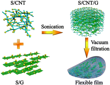
The synthesis process and the detailed structure of the S/CNT/G film are shown in Fig. 1. In our approach, the 3D S/CNT/G material composed of carbon nanotubes and graphene with uniform sulfur distribution is successfully obtained via a solution-based fabrication process. Under ultrasound treatment, the CNTs and graphene in the mixed solution form a 3D network and sulfur uniformly anchors on the carbon network without aggregation. The mixed solution was vacuum-filtered, and the free-standing film could be peeled off after drying, which was used as a flexible cathode for lithium–sulfur batteries.The morphology of the S/CNT/G film under different magnification was investigated by SEM, as shown in Fig. 2(a)–(c). Fig. 2(a) exhibits the overall surface morphology of the S/CNT/G film, and some graphene sheets can be found. By magnifying the film as shown in Fig. 2(b) and (c), the film shows a 3D carbon framework composed of carbon nanotubes and graphene. This structure is made up of numerous carbon nanotubes optionally interlacing with one another or closely overlapping on the surface of graphene, thereby forming a large number of voids. The carbon framework with a porous structure can offer sufficient space for polysulfide accommodation and sulfur volume expansion. In addition, the surface areas of graphene are observed, thereby implying that graphene tends to lie horizontally and interlace with nanotubes in the film. The S/CNT/G film was investigated by EDX mapping, and the elemental distribution results are presented in Fig. 2(d)–(f). As shown in Fig. 2(d), the S/CNT/G film has two elements, namely, carbon and sulfur. Sulfur appears in the carbon framework. The distributions of both carbon and sulfur are uniform in Fig. 2(e) and (f), thereby confirming that the sulfur nanoparticles are homogeneously distributed in the carbon nanotubes/graphene framework without large aggregation.
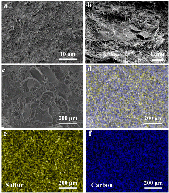 | ||
| Fig. 2 SEM images of the S/CNT/G film at different magnifications (a)–(c). EDX mappings of the S/CNT/G film (d), sulfur mapping (e) and carbon mapping (f). | ||
The structure of the S/CNT/G film was characterized by XRD, and the result is shown in Fig. 3(a). In the S/CNT/G film, characteristic peaks at around 2θ = 22.2° and 26.2° can be observed, which are attributed to the (002) plane of the carbon nanotubes and graphene. The clear peaks of orthorhombic sulfur in the S/CNT/G film can be indexed to standard sulfur (JCPDS no. 08-0247). For comparison, the intensity of sulfur peaks was relatively weaker in the S/CNT/G film, which agrees with the Raman analysis. Evidently, all the clear peaks in the XRD pattern can be perfectly indexed to sulfur, nanotubes, and graphene, thereby proving that sulfur nanoparticles were embed uniformly in the 3 D carbon nanotube/graphene framework. The TGA test was conducted on the S/CNT/G film in a N2 atmosphere with a heating rate of 10 °C min−1 from 25 °C to 800 °C. In Fig. 3(b), one obvious slope occurs at about 200 °C and was finished at about 350 °C. Subsequently, no further weight loss of the composite film was observed, thereby implying that the major mass loss of the film is due to sulfur evaporation. A weight loss cannot be seen in the pure CNT/G film in contrast to the S/CNT/G film. Through calculation, the sulfur content of the synthesized S/CNT/G film was determined to be 50 wt% and 67 wt%. The sulfur content of S/CNT/G films was 50 wt% and 67 wt%, which were named S/CNT/G-50 and S/CNT/G-67, respectively. The Raman spectra of the CNTs, graphene and S/CNT/G film are presented in Fig. S1.† All the samples showed two strong peaks at around 1353 and 1585 cm−1, corresponding to disordered carbon (D-band) and crystalline graphite carbon (G-band), respectively. For comparison, the intensity of sulfur peaks was relatively weaker in the S/CNT/G film, which agrees with the Raman analysis. The three sharp peaks of the S/CNT/G film below 600 cm−1 could be assigned to the S–S bond in the composites, while the one at 485.5 cm−1 characteristic of a S–S stretching vibration is identical to that of pure sulfur powder.
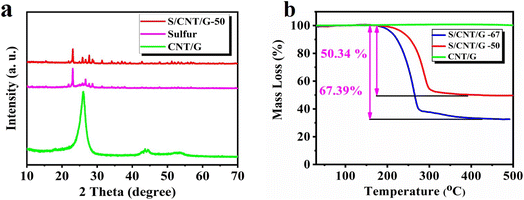 | ||
| Fig. 3 XRD patterns (a) and TGA curve (b) of sulfur, the CNT/G film and the S/CNT/G film with different sulfur contents. | ||
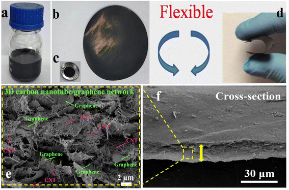
The flexible S/CNT/G-50 film synthesis process is shown in Fig. 4(a) and (b). The colloidal dispersion of the as-synthesized S/CNT/G-50 in deionized water is shown in Fig. 4(a). The S/CNT/G dispersion is black and stabilizable, in which nano-sulfur, CNTs, and graphene are simultaneously suspended to form a uniform mixture. In Fig. 4(b), a free-standing S/CNT/G film with an interwoven nanotube network, centimetre width and a few tens of micrometers thickness is obtained after filtrating. The diameter of the S/CNT/G film is 47 mm, and the surface is relatively smooth. The film also shows good flexibility and toughness. As shown in Fig. 4(c), the circular shaped S/CNT/G-50 film is ready for use as a binder-free, flexible cathode in a 2025 type coin cell. Fig. 4(d) displays the images of a bent S/CNT/G film. The film can be flexed backward and forward repeatedly without fractures being generated. When directly used as a working electrode for assembling batteries, the film can be cut into small disks (12 mm in diameter) and can resist the sealing pressure without any damage. These characteristics are mainly due to carbon nanotubes strongly entwined with one another. The typical cross-section SEM images of the S/CNT/G-50 film are displayed in Fig. 4(e) and (f). As shown in Fig. 4(f), the thickness of the composite film is about 20 μm. By magnifying the section morphology of the film in Fig. 4(e), carbon nanotubes and graphene are seen wrapped around each other, and no large particles or aggregates are observed. Note that the CNT and graphene are intertwining with each other to form a network nanostructure, which come into being a 3D conductive framework for sulfur accommodation. The interior and cross-sectional morphologies can also confirm that the one-dimensional carbon nanotubes and two-dimensional graphene serve as a 3D matrix to restrain zero-dimensional nano-sulfur, polysulfides, and lithiation products. Compared with the surface nanostructure in Fig. 2(b), the morphology of the cross-section of the film also shows a porous structure, indicating a sufficiently homogeneous dispersion of sulfur, carbon nanotubes, and graphene after intensive ultrasonication. Mainly edges of the graphene sheets are observed in the cross-section view, thereby suggesting that graphene tends to lie horizontally in the film. The EDX elemental analysis in Fig. S2† shows that elemental sulfur is well distributed across S/CNT/G film-50.
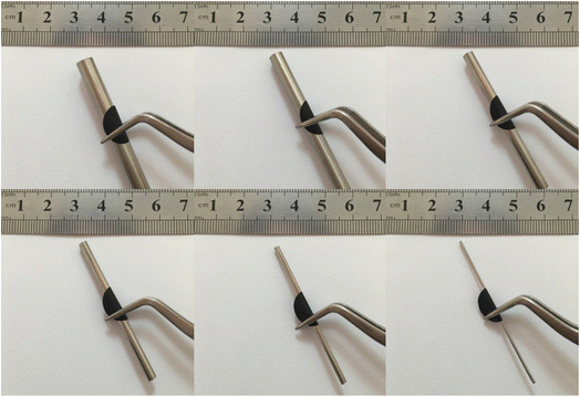
In order to learn about the flexibility and mechanical robustness of S/CNT/G film-50, the S/CNT/G film is bent around six stainless steel sticks with different diameters (6–1 mm), respectively. The results of the test are shown in Fig. 5. The film can be readily rolled and folded without cracks, even easily bent around a rod as small as 1 mm in diameter under a very large bending angle, exhibiting excellent flexibility. It proves that the flexible and mechanical robust S/CNT/G film can be directly used as an electrode in the absence of a binder and current collector.
Transmission electron microscopy (TEM) was employed to investigate the detailed structure of the S/CNT/G film at different magnifications. Fig. 6(a) reveals that the 3D carbon framework is constructed from 1D carbon nanotubes (Fig. S3†) and 2D graphene intertwined with one another, which coincided with SEM observations. In Fig. 6(b) and (c), the nanostructure of graphene is wrinkled, laminar, and stacked with some carbon nanotubes. The carbon nanotubes with a tubular structure strongly entwine with each other and overlap on graphene. Sulfur nanoparticles have an average diameter of 30–50 nm (Fig. 6(d) and S3†). In addition, sulfur nanoparticles are individually covered in the carbon framework without obvious aggregation. Sulfur nanoparticles are uniformly dispersed in the carbon matrix by intensive ultrasonication. According to the TEM images of S/CNT/G composite, we find that the as-prepared S/CNT/G film is assembled from interweaved carbon nanotubes and graphene with sulfur nanoparticles homogeneously distributed in the carbon skeleton. The 3 D framework can result in fast pathways for electronic and Li ion ingress/egress of the electrolyte within the structure. Thus, we may achieve the predicted purpose of the preparation of the S/CNT/G film with a 3D conductive framework, which can be applied as a flexible electrode with enhanced electrochemical performance.
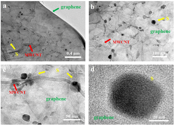 | ||
| Fig. 6 TEM images (a), (b) and (c) of the S/CNT/G film at different magnifications. (d) HRTEM image of one nano-sulfur nanoparticle on graphene. | ||
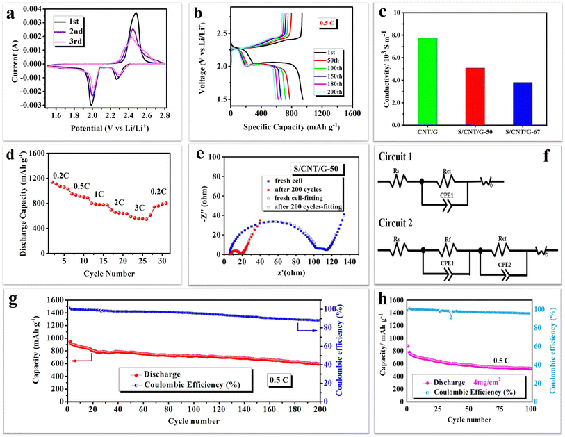
To demonstrate the structural features of the 3D conductive framework, the as-obtained S/CNT/G film is employed as a flexible cathode to study electrochemical performance. Fig. 7(a) presents the first three cyclic voltammograms (CV) of the S/CNT/G film at a scan rate of 0.1 mV s−1, in the range 1.5–2.8 V. The CV curves have two typical reduction peaks and one oxidation peak, which were in accordance with the reaction mechanism of sulfur in previous studies.37,38 The peak at 2.3 V can be related to the reduction of sulfur to higher-order polysulfides (Li2Sn, 4 ≤ n ≤ 8), and the peak at 2.05 V results from further conversion of the soluble polysulfides to insoluble Li2S2/Li2S. In the anodic scan process, the oxidation peak at approximately 2.55 V is assigned to the transformation of Li2S2/Li2S to polysulfides, and eventually, to sulfur. Moreover, the CV peak profiles overlapped well during the three cycles, revealing the good electrochemical reversibility of the flexible film cathode.
Fig. 7(b) displays the galvanostatic charge/discharge profiles of the S/CNT/G film for at 0.5C. The S/CNT/G film shows characteristic charge–discharge plateaus, which coincide with the transformation of sulfur/polysulfides that occurred during the reaction. The first plateau at 2.25 V can be attributed to the changes of elemental sulfur to higher-order lithium polysulfides (Li2Sn, 4 ≤ n ≤ 8). The second plateau at around 2.05 V corresponds to the reduction of higher order lithium polysulfides to lower-order lithium polysulfides (Li2S2/Li2S).39 They are in keeping with the position of reduction peaks in CV curves. Notably, the second plateaus corresponding to the formation of polysulfides are longer and are very stable during the discharge, thereby contributing to the main discharge capacity. Thus, the film is suggested to play an effective role in inhibiting polysulfide dissolution. The conductivity of the S/CNT/G film cathode was tested by using a four-point collinear probe method as shown in Fig. 7(c). The high conductivity of the CNT/G film and S/CNT/G-50 film reached 7.75 × 10³ and 5.08 × 10³ S m−1. It is noted that the conductivity of the S/CNT/G-50 film decreases compared to a pure CNT/G film, and it still shows a high conductivity of 5.08 × 10³ S m−1.
The S/CNT/G film was further studied at various rates, and the results are shown in Fig. 7(d). The film electrode presents clear changes with the different rates. The discharge capacities of the film are 1176–999, 958–881, 856–766, and 715–635 mA h g−1 at 0.2, 0.5, 1, and 2C, respectively. When the rate comes back to 0.2C, the film shows a reversible discharge capacity of 539–773 mA h g−1. Even at a high rate of 3C, the film still reaches a high discharge capacity of 598–545 mA h g−1, thereby showing good rate performance. The improved rate capacity of the S/CNT/G film benefits from the 3D carbon nanotube/graphene framework with high porosity, which not only affords a large specific surface area for sulfur reaction, but also increases the effective contact area between the active material and the electrolyte, thereby leading to fast Li ion diffusion. Moreover, in this 3D framework, sulfur nanoparticles are homogeneously distributed in the carbon skeleton and are closely anchored to the conductive components, thereby greatly shortening the electron transfer pathway in the sulfur cathode and resulting in superior high-rate performance.
Fig. 7(e) and (f) display the EIS curves and the equivalent circuits of the S/CNT/G-50 film in different configurations before cycling and after 200 cycles. The test frequency was between 0.01 Hz and 100 kHz, and the perturbation amplitude was 5 mV. Before cycling, the Nyquist plot of the S/CNT/G-50 film electrode consists of two semicircles and an inclined line. The semicircle in the high frequency region can be ascribed to a passivation film, and the second depressed semicircle in the medium frequency region corresponds to charge transfer resistance. The inclined line in the low frequency region probably represents the Li ion diffusion resistance in active materials. After 200 cycles, the Nyquist plot of the S/CNT/G film electrode changes to one semicircle in the high frequency region and an inclined line. From EIS, it can be observed that charge transfer resistance decreased after 200 cycles compared with the fresh cell, thereby indicating that sulfur/polysulfides were closely in contact with the conductive framework provided by the flexible, free-standing film electrode, which decreases the charge transfer resistance. The fitting results of the S/CNT/G-50 cathode are summarized in Table S1.† According to the fitting results, the fitted resistance parameters of the cathode material before cycling are Rs = 5.0 Ω, Rf = 98.9 Ω, and Rct = 34.7 Ω, and the Rs of the cathode material after 200 cycles is 7.2 Ω, and Rct = 9.9 Ω. Rs, Rct and Rf represent the internal resistance, charge transfer resistance and interfacial resistance between the electrolyte and electrode, respectively.
The long-term cycling performance and corresponding coulombic efficiency curves of the S/CNT/G-50 film electrode are shown in Fig. 7(g), and the S/CNT/G film with 4 mg cm−2 was tested as shown in Fig. 7(h). The film electrode shows an initial specific discharge capacity as high as 948 mA h g−1 at 0.5C. In the subsequent cycles, the film electrode keeps a reversible capacity of 593 mA h g−1 after 200 cycles. The capacity retention of the film is 63%. The enhanced cycle stability of the film cathode can be attributed to the well-designed nanostructure of the 3D conductive carbon framework. The 1D carbon nanotubes interweave together to form a skeleton for sulfur/polysulfide accommodation, and the 2D graphene provides an additional protective layer to restrict polysulfide dissolution in the electrolyte. In addition, the S/CNT/G-50 film offers a hierarchical framework for the homogeneous distribution of sulfur nanoparticles, thereby greatly enabling the high utilization of active materials and further improving the electrochemical performance of the film electrode. The average coulombic efficiency of the film is 94.4% over 200 cycles. We can see that the coulombic efficiency remains above 96% during the first 100 cycles and decreases slowly in the subsequent cycles. This may have been caused by the consumption of LiNO3 during cycling. We added 0.1 M LiNO3 into the electrolyte to improve the stabilization of the Li/electrolyte interface in LiTFSI according to the method used in previous research. However, LiNO3 would decompose after long cycling, thereby decreasing the effect on restraining polysulfide shuttle and further decreasing the coulombic efficiency of the film electrode. Fig. 7(h) shows the cycling performances of the S/CNT/G film cathode with a high sulfur content and with a high sulfur content and an increasing areal sulfur loading of 4 mg cm−2 was tested at 0.5C. Initial specific discharge capacities of 878 mA h g−1 and 522.7 mA h g−1 after 100 cycles were achieved. The average Coulomb efficiency is 97.5%, which shows a slight decay after 100 cycles. To further demonstrate the advance of this work, Table S2† collects and compares the performance of the current work with carbon nanotube and graphene materials in lithium–sulfur batteries. The sulfur loading and cycling performance of the S/CNT/G film were superior or comparable to those of the other materials in Table S2.†
An adsorption experiment was done to further confirm the capability of the CNT/G carbon matrix in suppressing polysulfide species. As shown in Fig. 8(a), 10 mg of CNT/G film was added to LiPS solution and let it stand for about 12 h, and the solution of the CNT/G film is much clearer than CNT film solution, further confirming that the CNT/G film is more effective in adsorbing polysulfides. The UV-Vis absorption spectra of the CNT/G film after soaking in Li2S6 solution were further investigated as shown in Fig. 8(b). The typical peak at around 350 nm can be attributed to S62−. It could be obviously observed that the CNT/G film shows the lowest absorption peak of LiPSs, which proved that the 3D carbon matrix with a larger specific surface area is beneficial to the physical adsorption of LiPSs.
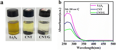 | ||
| Fig. 8 (a) Color variations of the Li2S6 solution; (b) UV-Vis absorption spectra of the S/CNT/G film and after soaking in Li2S6 solution. | ||
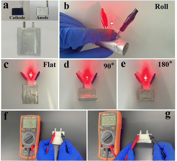
In order to show the application of the S/CNT/G film for flexible devices, a Li–S pouch battery was fabricated and mechanical deformation tests were conducted. The Li–S pouch battery was coupled with a Li/copper foam anode and S/CNT/G cathode as shown in Fig. 9(a). In Fig. 9(b)–(e), the S/CNT/G-based flexible Li–S battery can light up red light-emitting diodes (LEDs) under flat, bent, and even rolled states. When the battery is bent at different angles (0°, 90°, and 180°), no difference in the brightness is observed, demonstrating that the S/CNT/G based flexible battery coupled with a Li/copper foam anode and S/CNT/G cathode is highly suitable for flexible and wearable energy systems. The cycling performance and the corresponding coulombic efficiencies of the S/CNT/G cathode in the pouch Li–S battery were examined in bent–unbent states as shown in Fig. S4.† The galvanostatic discharge–charge profiles under 0.1C in the first cycle is presented in Fig. S5,† showing the typical two-plateau discharge characteristics. The initial capacity reached 1243 mA h g−1 (unbent) and 1110 mA h g−1 (bent) in the 5th cycle, and the coulombic efficiencies were nearly 100% under bent–unbent states. These results indicate the good flexibility and stable electrochemical performance of the flexible S/CNT/G cathode revealing considerable potential for practical application in flexible devices.
Conclusions
In summary, we have successfully fabricated a free-standing, binder-free, and current collection-free sulfur/carbon nanotube/graphene (S/CNT/G) film as a highly conductive framework for lithium-sulfur batteries via a vacuum filtration method. This porous S/CNT/G film exhibits an initial capacity of 948 mA h g−1, which decreases to 593 mA h g−1 after 200 cycles at 0.5C. Even at a high rate of 3C, it still delivers 598 mA h g−1. The optimal electrochemical performance is due to the 3 D framework, which consists of carbon nanotubes and graphene. Such a composition ameliorates the conduction of sulfur, shortens the transmission path for Li ions, sustains the strain caused by the sulfur volume expansion, and accommodates polysulfides during cycling. This excellent electrochemical performance demonstrates that this free-standing, binder-free, and current collector-free S/CNT/G film has high potential for application as a cathode material for lithium–sulfur batteries.Data availability
Data and research materials will be available on request.Conflicts of interest
The authors declare no conflict of interest.Acknowledgements
This work was supported by the National Natural Science Foundation of China (No. 21771165); Natural Science Foundation of Henan Province (No. 222300420576 and 212300410295); Key Scientific Research Projects of Universities in Henan Province (No. 21A480011 and 21A530008); Science and Technology Project of Henan Province (No. 172102210082); Aeronautical Science Foundation of China (No. 2016ZF55015).References
- R. Pai, A. Singh, M. H. Tang and V. Kalra, Commun. Chem., 2022, 5, 1–11 CrossRef.
- J. Guo and J. Liu, Nanoscale Adv., 2019, 1, 2104–2122 RSC.
- D. Y. Wang, Y. Si, W. Guo and Y. Fu, Nat. Commun., 2021, 12, 3220 CrossRef CAS PubMed.
- E. Venezia, L. Carbone, F. Bonaccorso and V. Pellegrini, Nanoscale Adv., 2022, 4, 1136–1144 RSC.
- D. Luo, C. Li, Y. Zhang, Q. Ma, C. Ma, Y. Nie, M. Li, X. Weng, R. Huang, Y. Zhao, L. Shui, X. Wang and Z. Chen, Adv. Mater., 2022, 34, e2105541 CrossRef PubMed.
- S. Wang, S. Feng, J. Liang, Q. Su, F. Zhao, H. Song, M. Zheng, Q. Sun, Z. Song, X. Jia, J. Yang, Y. Li, J. Liao, R. Li and X. Sun, Adv. Energy Mater., 2021, 11, 2003314 CrossRef CAS.
- Y. Cai, C. Liu, Z. Yu, H. Wu, Y. Wang, W. Ma, Q. Zhang and X. Jia, J. Power Sources, 2022, 537, 231478 CrossRef CAS.
- B. Li, H. Xu, Y. Ma and S. Yang, Nanoscale Horiz., 2019, 4, 77–98 RSC.
- S. Tang, X. Li, Q. Fan, X. Zhang, D. Y. Wang, W. Guo and Y. Fu, J. Electrochem. Soc., 2022, 169 DOI:10.1149/1945-7111/ac638c.
- R. Steudel and T. Chivers, Chem. Soc. Rev., 2019, 48, 3279–3319 RSC.
- P. Y. Chen, C. Yan, P. Chen, R. Zhang, Y. X. Yao, H. J. Peng, L. T. Yan, S. Kaskel and Q. Zhang, Angew. Chem., Int. Ed., 2021, 60, 18031–18036 CrossRef CAS PubMed.
- B. Yang, D. Guo, P. Lin, L. Zhou, J. Li, G. Fang, J. Wang, H. Jin, X. Chen and S. Wang, Angew. Chem., Int. Ed., 2022, 61, e202204327 CAS.
- T. Wang, Q. Zhang, J. Zhong, M. Chen, H. Deng, J. Cao, L. Wang, L. Peng, J. Zhu and B. Lu, Adv. Energy Mater., 2021, 11, 2100448 CrossRef CAS.
- W. Gao, Y. Liu, C. Cao, Y. Zhang, Y. Xue and C. Tang, J. Colloid Interface Sci., 2022, 610, 527–537 CrossRef CAS PubMed.
- W. Xiao, S. Oh, T. V. M. Sreekanth, J. Kim and K. S. Yoo, ACS Appl. Energy Mater., 2022 DOI:10.1021/acsami.2c09081.
- S. K. Kannan, H. Hareendrakrishnakumar, J. Joseph and M. G. Joseph, Energy Fuels, 2022 DOI:10.1021/acs.energyfuels.2c01369.
- Y. Liu, Z. Che, X. Lu, X. Zhou, M. Han, J. Bao and Z. Dai, Nanoscale Adv., 2020, 2, 583–604 RSC.
- Y. Wu, D. Li, J. Pan, Y. Sun, W. Huang, M. Wu, B. Zhang, F. Pan, K. Shi and Q. Liu, J. Mater. Chem. A, 2022 10.1039/d2ta03421b.
- L. Li, Z. Ma and Y. Li, Carbon, 2022, 197, 200–208 CrossRef CAS.
- S. Zeng, J. Peng, X. Liang, X. Wu, H. Zheng, H. Zhong, T. Guo, S. Luo, J. Hong, Y. Li, Q. Wu and W. Xu, Nanoscale, 2022, 14, 9401–9408 RSC.
- X. Dai, K. Zou, W. Jing, P. Xu, J. Sun, S. Guo, Q. Tan, Y. Liu, T. Zhou and Y. Chen, J. Mater. Chem. A, 2022 10.1039/d2ta04363g.
- Y. Shao, F. Chen, N. Ren, S. Wang, J. Wang, Z. Wen and C. Chen, Chem. Commun., 2022, 58, 7570–7573 RSC.
- X. Dong, M. Wang, Y. Feng, J. Zhang, Y.-D. Cao, G. Gao, Y. Zhang and L.-L. Fan, Dalton Trans., 2022 10.1039/d2dt01743a.
- C. Wang, N. Sakai, Y. Ebina, T. Kikuchi, M. R. Snowdon, D. Tang, R. Ma and T. Sasaki, J. Mater. Chem. A, 2021, 9, 9952–9960 RSC.
- S.-C. Sun, Y. Xu, J.-L. Wen, T.-Q. Yuan and R.-C. Sun, Green Chem., 2022 10.1039/d2gc01503j.
- L. Yuanzheng, Y. Zhicheng, M. Lianghao, L. Buyin and L. Shufa, Nanoscale Adv., 2022, 4, 2189–2195 RSC.
- Z. Cao, J. Guo, J. Jia, Z. Zhang, Y. Yin, M. Yang and S. Yang, Electrochim. Acta, 2022, 422, 140549 CrossRef CAS.
- K. Jin, X. Zhou, L. Zhang, X. Xin, G. Wang and Z. Liu, J. Phys. Chem. C, 2013, 117, 21112–21119 CrossRef CAS.
- C. Wang, X. Wang, Y. Wang, J. Chen, H. Zhou and Y. Huang, Nano Energy, 2015, 11, 678–686 CrossRef CAS.
- L. Zhu, H.-J. Peng, J. Liang, J.-Q. Huang, C.-M. Chen, X. Guo, W. Zhu, P. Li and Q. Zhang, Nano Energy, 2015, 11, 746–755 CrossRef CAS.
- G. Zhou, S. Pei, L. Li, D. W. Wang, S. Wang, K. Huang, L. C. Yin, F. Li and H. M. Cheng, Adv. Mater., 2014, 26, 625–631 CrossRef CAS PubMed.
- Y. J. Yen and S. H. Chung, Chem. Commun., 2021, 57, 2009–2012 RSC.
- Y.-C. Ho and S.-H. Chung, Chem. Eng. J., 2021, 422 Search PubMed.
- L. Sun, W. Kong, Y. Jiang, H. Wu, K. Jiang, J. Wang and S. Fan, J. Mater. Chem. A, 2015, 3, 5305–5312 RSC.
- Y. Chen, S. Lu, X. Wu and J. Liu, J. Phys. Chem. C, 2015, 119, 10288–10294 CrossRef CAS.
- M. Wei, P. Yuan, W. Chen, J. Hu, J. Mao and G. Shao, Electrochim. Acta, 2015, 178, 564–570 CrossRef CAS.
- Y. Ouyang, W. Zong, X. Zhu, L. Mo, G. Chao, W. Fan, F. Lai, Y. E. Miao, T. Liu and Y. Yu, Adv. Sci., 2022, e2203181, DOI:10.1002/advs.202203181.
- Y. Liu, Y. Elias, J. Meng, D. Aurbach, R. Zou, D. Xia and Q. Pang, Joule, 2021, 5, 2323–2364 CrossRef CAS.
- J. Smajic, S. Wee, F. R. F. Simoes, M. N. Hedhili, N. Wehbe, E. Abou-Hamad and P. M. F. J. Costa, ACS Appl. Energy Mater., 2020, 3, 6805–6814 CrossRef CAS.
Footnote |
| † Electronic supplementary information (ESI) available. See https://doi.org/10.1039/d2na00494a |
| This journal is © The Royal Society of Chemistry 2022 |

