 Open Access Article
Excellent performance supercapacitors with the compounding of Ni(OH)2 and ZIF-67 derived Co–C–N nanosheets as flexible electrode materials†
Dequan
Li
,
Congcong
Shen
,
Qiang
Lu
,
Ruihan
Yan
,
Bin
Xiao
,
Baoye
Zi
,
Jin
Zhang
,
Qingjie
Lu
* and
Qingju
Liu
 *
*
Yunnan Key Laboratory for Micro/Nano Materials & Technology, National Center for International Research on Photoelectric and Energy Materials, School of Materials and Energy, Yunnan University, Kunming 650091, P. R. China. E-mail: qjliu@ynu.edu.cn; 2789584342@qq.com; Tel: +86 871 65032713
First published on 21st September 2022
Abstract
Owing to the advantages of high theoretical capacity, low cost, and excellent chemical stability, Ni(OH)2 is considered as a potential candidate for electrode materials of supercapacitors. However, its further applications are limited by its adverse surface chemical properties. In this paper, a composite material consisting of ZIF-67 derived Co–C–N nanosheets and Ni(OH)2 was synthesized facilely on carbon cloth in situ, and based on the collective advantages of the various components, excellent electrochemical performance could be achieved when used as a flexible electrode material of supercapacitors. In detail, the as-obtained sample Ni(OH)2/Co–C–N/CC exhibits an ultrahigh specific capacitance of 2100 F g−1 at a current density of 1 A g−1. Moreover, the further assembled asymmetric supercapacitor device exhibits a maximum energy density of 78.6 W h kg−1 at a power density of 749.4 W kg−1. Furthermore, the device also shows outstanding cycling stability with 90.2% capacitance retention after 5000 cycles of charge–discharge. Basically, the remarkable performance can be attributed to the well-developed structure, abundant active sites, complex beneficial components, and their intrinsic properties. Significantly, rational design can broaden the research directions of corresponding electrode materials.
1 Introduction
To meet the challenges of energy demand and achieve sustainable development, high-power energy storage and conversion devices such as solar cells, lithium-ion batteries, fuel cells, and supercapacitors (SCs) have been developed vigorously in recent years.1–4 SCs have attracted much attention due to their high power density, fast charging and discharging speed, and long cycle life.5,6 However, compared to batteries, the low energy density of SCs is the biggest shortcoming limiting their development.7 Based on the equation of energy density, it is known that the energy density of SCs is proportional to the specific capacitance (C) and operating voltage (V), so enhancing the voltage window and capacity is fundamental to improving the energy density of SCs. Through the compounding of different conductive materials such as metal oxides, metal hydroxides, carbon materials, and MOFs, the synergy between different components can help construct diverse heterogeneous structures as well as improve the surface properties of the materials, thus overcoming the shortcomings of single materials such as inferior electrical conductivity, poor cycling stability, and low specific capacitance, improving the electrochemical capacity of the electrode materials and achieving a higher energy density of SCs while maintaining high power density.8–10Among the many metal oxides/hydroxides, Ni(OH)2 has gained more attention due to its high theoretical capacity, high chemical stability, and high multiplicity.11 However, the lower surface-dependent activity of metal hydroxides compared to metal oxides has led to a lower power density of Ni(OH)2. Poor electrical conductivity and cycling stability have also hindered the practical application of Ni(OH)2.12,13 To overcome these obstacles, it was found that forming composites by combining Ni(OH)2 with carbonaceous materials or other metal compounds is an effective strategy. Fan14et al. grew Co3O4/Ni(OH)2 honeycomb arrays in situ on nickel foam, and the specific capacitance of Co3O4/Ni(OH)2 reached 4396 F g−1 at a current density of 1 A g−1, which is higher than that of Co3O4 and the theoretical capacitance of Ni(OH)2. Hu15et al. prepared Co/C@Ni(OH)2 nanocomposites, which showed a specific capacitance of 866.8 F g−1 at a current density of 1 A g−1. Therefore, by forming composites of Ni(OH)2 with carbon materials or metal compounds, the shortcomings of Ni(OH)2 as an electrode material can be overcome and it is an effective strategy to prepare electrode materials with excellent performance.
In addition to the preparation of nanocomposites, a rational design of the structure of the material can also be effective in improving the kinetics of electrochemical reactions.16 Metal–organic frameworks (MOFs) are crystalline porous materials.17,18 The use of MOFs as templates to prepare nanoporous materials can effectively increase the porosity and specific surface area of the materials, thereby generating more active sites, shortening ion diffusion paths, and achieving high performance electrode materials.19,20 Nonetheless, the lack of conductivity and the low specific capacitance of MOFs limit their application in supercapacitors, and the commonly employed strategy is to compound them with other conductive materials and design layered structures to achieve more ion transport channels. Therefore, Ni(OH)2 was compounded with MOF-derived porous materials to make full use of the advantages of a single material and to prepare electrode materials with excellent performance. Ahmad21et al. prepared nanosheet composite structures of nitrogen-doped nanotubes and Ni(OH)2 derived from ZIF-67, showing a specific capacitance of 1636 F g−1 at a current density of 1 A g−1. Bao22et al. successfully constructed a series of Co3O4 embedded α-Co/Ni(OH)2 hollow nanocages using ZIF-67, which showed a specific capacitance of 1000 F g−1 at a current density of 1 A g−1. In addition, the conventional ball milling method for fabricating electrodes requires the addition of binders, which increases the interfacial resistance and reduces the exposure of active sites. Therefore, the use of MOFs as precursors to construct structurally stable and high-performance low-dimensional nanoporous binder-free flexible electrodes directly on substrates remains a focus of interest.23,24
Given the above, in order to overcome the defects of single electrode materials, improve the electrochemical performance of the electrode material, and realize a supercapacitor with high energy density while maintaining high power density, we used carbon cloth as a substrate to convert Co cations into Co nanoparticles by carbonizing the ZIF-67 organic backbone. The Co nanoparticles were embedded uniformly in the carbon backbone to form Co, C, and N self-doped nanosheets, and then Ni(OH)2 nanoparticles were grown uniformly on the Co–C–N nanosheets by a simple hydrothermal reaction to form Ni(OH)2/Co–C–N/CC nanocomposites. Heterojunctions and fluffy, porous nanosheet structures accelerate charge transfer and facilitate electrochemical response. As a result, the binderless electrode prepared on CC showed a high specific capacitance of 2100 F g−1 at 1 A g−1 and excellent multiplicative performance of 70% at 20 A g−1. The assembled asymmetric SCs showed a high energy density of 78.6 W h kg−1 at a power density of 749.4 W kg−1 and excellent cycling stability with 90.2% retention of the original capacitance after 5000 cycles at 10 A g−1. As expected, Ni(OH)2/Co–C–N/CC binder-free flexible electrodes have a greater prospect of application in the field of asymmetric flexible SCs.
2 Experimental section
2.1 Pretreatment of carbon cloth
Firstly, commercial carbon cloth (CC, 2 × 2 cm) was cleaned with absolute ethyl alcohol, acetone, and de-ionized water in sequence by ultrasonication for 30 min, and then placed in 30 mL of 1 M HCl aqueous solution with ultrasonication for 1 h to initiate an activation process. Finally, the cloth was dried in a vacuum oven at 60 °C for 10 h after being washed repeatedly with de-ionized water.2.2 Preparation of Co–C–N/CC
Firstly, 50 mL of 0.1 M 2-methylimidazole (C4H6N2) and 50 mL of 12.5 mM Co(NO3)2·6H2O were mixed by stirring for 5 min, and then the carbon cloth was placed in the mixture for 4 h to grow ZIF-67 on it. Subsequently, the cloth was dried at 60 °C for a night after being washed gently with absolute ethyl alcohol and de-ionized water. After drying, the cloth was transferred into a tube furnace and sintered at 450 °C for 2 h in a N2 atmosphere with a heating rate of 3 °C min−1. Moreover, 2-methylimidazole with different concentrations of 0.05 M, 0.2 M, and 0.3 M were applied for the same steps.2.3 Preparation of Ni(OH)2/Co–C–N/CC
Ni(OH)2 was attached to ZIF-67 by a facile hydrothermal method. In detail, the above cloth was immersed in 50 mL of 50 mM Ni(NO3)2·6H2O aqueous solution and transferred into a 100 mL Teflon-lined stainless steel autoclave to proceed with the hydrothermal process at 80 °C for 3 h. Then, the target sample Ni(OH)2/Co–C–N/CC-50 was obtained after washing and drying. Moreover, Ni(OH)2/Co–C–N/CC-30 and Ni(OH)2/Co–C–N/CC-70 samples were also prepared for comparison by using 30 mM and 70 mM Ni(NO3)2·6H2O aqueous solutions following the same steps. The sample loadings ranged from 0.9 to 1.5 mg.2.4 Materials characterization
X-ray diffraction (XRD, TTRIII, Rigaku Co. Ltd, Japan) was utilized to analyze the phases and crystal structure of the samples. The elements in the compounds were measured via X-ray photoelectron spectroscopy (XPS, K-α spectrograph, Thermo Fisher Scientific Co. Ltd, USA) with Al Kα excitation (1486.6 eV). Scanning electron microscopy (SEM, Nova450, Thermo Fisher Scientific Co. Ltd, USA) and transmission electron microscopy (TEM, JEM-2100, JEOL Co. Ltd, Japan) were conducted to analyze and observe the microcosmic morphology.2.5 Electrochemical measurements
The overall electrochemical performances of the prepared electrode materials were evaluated in an electrochemical workstation (CHI760E) with a standard three-electrode system in a 3 M KOH aqueous solution. Galvanostatic charge and discharge (GCD), cyclic voltammetry (CV), and electrochemical impedance spectroscopy (EIS) tests were carried out. Pt film and Hg/HgO electrode were used as counter electrodes and reference electrode, respectively. GCD tests were conducted in the potential range of 0–0.5 V and at various current densities from 1 to 20 A g−1. CV tests were conducted in the potential range of 0–0.5 V and various scan rates from 5 to 100 mV s−1. The EIS spectrum was measured in the frequency range of 0.01–100 kHz and at an amplitude of 5 mV.In the three-electrode system, the specific capacitance is calculated using the following formula:
 | (1) |
The performance of the assembled flexible asymmetric supercapacitor (ASC) was tested in a two-electrode system and the prepared Ni(OH)2/Co–C–N/CC was used as the positive electrode. All the related tests were conducted in 3 M KOH solution and the cycle stability was evaluated by analyzing the GCD curves of 5000 cycles charge and discharge at a current density of 10 A g−1.
In the two-electrode system, the capacitance (Cs), power density (P), and energy density (E) of the simple device are calculated using the following formulae:
 | (2) |
 | (3) |
 | (4) |
3 Results and discussion
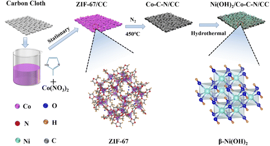
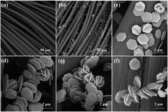
Fig. 1 shows a schematic diagram of the preparation process. From the perspective of crystal structure, ZIF-67 is a precursor with more active sites and good surface properties, and Ni(OH) is ordered and stacked into a hexagonal structure without any intercalation, which is a more stable crystal type. Specifically, Co–C–N nanosheets derived from ZIF-67 were prepared on flexible carbon cloth by co-precipitation and sintering in a N2 atmosphere, and further β-Ni(OH)2 loading on the nanosheets to form Ni(OH)2/Co–C–N/CC composites by a simple hydrothermal method.The microscopic morphology of the samples is characterized by SEM and TEM. According to Fig. 2a–c, the SEM images of ZIF-67 derived Co–C–N grown on pure carbon cloth exhibit an ortho-hexagonal nanosheet shape. The size distribution of the nanosheets is uniform, and the side length of each nanosheet is between 1.2 and 1.3 μm, but the thickness is only 60–70 nm. This giant lateral size and skinny nanosheet structure can efficiently shorten the ion and electron diffusion distance, enabling speedy ion diffusion and electron transport, therefore exhibiting remarkable electrochemical performance. According to Fig. 2d–f, Ni(OH)2 was successfully deposited on the Co–C–N nanosheets in the form of nanoparticles, and the amount of Ni(OH)2 nanoparticles on the Co–C–N nanosheets can be seen to increase gradually with increasing loading. Obviously, the loading of Ni(OH)2 nanoparticles did not destroy the well-developed microscopic morphology of the Co–C–N nanosheets but improved the superiority of the constituting structure. The more moderate loading of Ni(OH)2/Co–C–N/CC-50 ensures efficient electron and ion diffusion without causing excessive agglomeration as well as exhibits superior electrochemical properties.
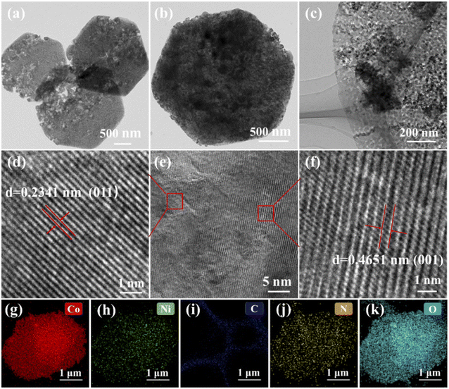
The morphology and micro-structure of the samples are further characterized by high-resolution transmission electron microscopy (HRTEM). As shown in Fig. 3a, TEM of the original nanosheets confirms their positive hexagonal structure with fluffy and obvious pores, which can offer abundant active sites for electron transfer and ion diffusion and further enhance the electrochemical performance. Fig. 3b and c display the TEM images of Ni(OH)2/Co–C–N/CC-50 and it can be seen that Ni(OH)2 grows on the nanosheets in the form of nanoparticles. According to the HRTEM image of Ni(OH)2/Co–C–N/CC-50 (Fig. 3d–f), the crystal lattice fringes of 0.2341 nm and 0.4651 nm can be clearly seen, which match perfectly with the (011) and (001) crystalline planes of Ni(OH)2 (JCPDF No. 74-2075). The elemental mapping of Ni(OH)2/Co–C–N/CC-50 is displayed in Fig. 3g–k, from which it can be seen that the carbon skeleton of ZIF-67 is retained and the elements Ni, Co, N, and O are uniformly distributed on the nanosheets, confirming the uniform growth of Ni(OH)2 on the Co–C–N nanosheets.
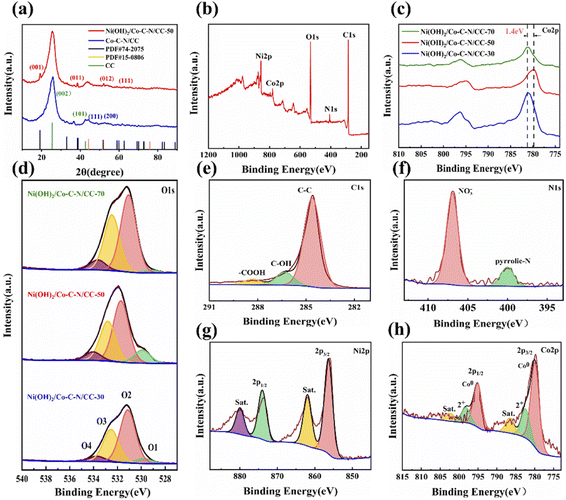
The crystal structure and phase compositions obtained from samples were further studied via X-ray diffraction (XRD). As shown in Fig. 4a, the peaks at 25.7° and 43° can be ascribed to amorphous carbon on carbon cloth.21 Two obvious peaks can be observed at 44.2° and 51.5°, which can be well indexed to the (111) and (200) crystalline planes of Co nanoparticles (JCPDF No. 15-0806). After the loading of Ni(OH)2, four diffraction peaks can be observed at 19.1°, 38.5°, 51.9°, and 59°, which can well be indexed to the (001), (011), (012), and (111) crystalline planes of hexagonal phase β-Ni(OH)2 (JCPDF No. 74-2075), indicating that the Ni(OH)2 particles were successfully loaded on the Co–C–N nanosheets with the size of Ni(OH)2 particles ranging from 18 to 22 nm.
The elemental composition and chemical state distribution of the prepared Ni(OH)2/Co–C–N/CC were further investigated by XPS. Fig. 4b displays the XPS survey spectrum of Ni(OH)2/Co–C–N/CC-50 and the presence of C, N, O, Co, and Ni elements without any other impurities are confirmed. Fig. 4c and d show the Co2p and O1s spectra of Ni(OH)2/Co–C–N/CC-30, Ni(OH)2/Co–C–N/CC-50, and Ni(OH)2/Co–C–N/CC-70, respectively. It can be seen that the Co2p spectrum of Ni(OH)2/Co–C–N/CC-50 exhibits a 1.4 eV negative shift, which can be attributed to the reduction of sectional Co2+ by oxygen vacancies derived from the activation of lattice oxygen (Co2+ → Co2−δ).25 As can be seen from Fig. 4d, the O1s can be deconvoluted into four peaks: O1, O2, O3, and O4, at 529.9 eV, 531.7 eV, 532.8 eV, and 534 eV respectively. O1 is related to the lattice oxygen in the bulk phase. Among the three samples, Ni(OH)2/Co–C–N/CC-50 displays the highest lattice oxygen concentration. Activation of lattice oxygen generates more oxygen vacancies; this was also verified by the electron paramagnetic resonance spectrum (Fig. S1†), where Ni(OH)2/Co–C–N/CC-50 showed a signal at a g value of 2.003. Oxygen vacancies increase the number of active sites and can better regulate the redox reaction of anions, thus effectively improving the electric capacity and cycling stability of the electrode materials.26–28 O2 is the peak corresponding to Ni–OH produced by loading Ni(OH)2 and the peak area of O2 gradually increases with increasing loading concentration.29 O3 and O4 can be attributed to OH, COOH and H2O adsorbed on the surface of the material.30 As shown in Fig. 4e, the high resolution of C1s displays three characteristic peaks at 284.6 eV, 286.31 eV, and 288.33 eV, which can be attributed to C–C, C–OH, and –COOH, respectively, indicating the presence of small amounts of functional groups on carbon cloth. The binding energies of the N1s spectrum as shown in Fig. 4f can be deconvoluted into two different peaks at 406.9 eV and 400.2 eV, which are attributed to NO3− and pyridine N, respectively. Pyridine N has excellent electron donor/acceptor properties and Faraday activity, and a certain amount of N doping can improve the electrochemical properties of the material.31 In Fig. 4g, the spectrum of Ni 2p displays two characteristic peaks at 856.3 eV and 873.6 eV, labeled Ni2p1/2 and Ni2p3/2, respectively. The spin separation energy is 17.3 eV, which is characteristic of the Ni2+, and two corresponding satellite peaks are also observed at 861.9 eV and 879.9 eV.32 For the Co 2p spectrum as shown in Fig. 4h, the peaks centered at 779.9 eV and 795 eV correspond to Co0, while the peaks located at 782.7 eV and 798.5 eV are assigned to Co2+, and two weak satellite peaks are located at 786.8 eV and 802.6 eV.17
To evaluate the electrochemical performance, Co–C–N/CC and Ni(OH)2/Co–C–N/CC based working electrodes were tested in a three-electrode system with Pt counter electrode and Hg/HgO reference electrode while the electrolyte was 3 M KOH aqueous solution. As shown in Fig. 5a and S2,† from the CV and GCD curves of Co–C–N/CC at 30 mV s−1 scan rate and a current density of 1 A g−1, it can be seen that the curve corresponding to the concentration of 0.1 M 2-methylimidazole has the biggest area and maximum discharge time, indicating that the nanosheets produced with different ligand concentrations have different properties. Therefore, Co–C–N/CC prepared with 2-methylimidazole concentration of 0.1 M was chosen for the loading of different concentrations of Ni(OH)2. As displayed in Fig. 5b, among the CV curves of Ni(OH)2/Co–C–N/CC at 0–0.5 V voltage window with a scan rate of 30 mV s−1 Ni(OH)2/Co–C–N/CC-50 has the maximum integral area. The corresponding GCD curves are shown in Fig. 5c; after calculation, the specific capacitances of Ni(OH)2/Co–C–N/CC-30, Ni(OH)2/Co–C–N/CC-50, and Ni(OH)2/Co–C–N/CC-70 are 648.2, 2100 and 170 F g−1 at a current density of 1 A g−1, respectively. It is found that there is an optimum concentration to obtain the best electrochemical capacitance when the heterojunction is formed. According to Fig. 5d, Ni(OH)2/Co–C–N/CC-50 displays similar shapes at different scan rates from 5 to 100 mV s−1 in the voltage range of 0–0.5 V, and the peak current increases with increasing scan rate, indicating good rate capability, and fast electron and ion transport.5 Notably, as the scan rate increases, the oxidation peak moves toward the positive potential while the reduction peak moves toward the negative potential, which may be related to the increase in the internal diffusion resistance, which limits the ion diffusion to meet the electron neutralization during the fast Faraday reaction.33–35 GCD curves of Ni(OH)2/Co–C–N/CC-50 at different current densities from 1 to 20 A g−1 as shown in Fig. 5e, the two plateaus in the charging and discharging curves correspond to the oxidation and reduction peaks inside the CV curves in Fig. 5d, respectively. As shown in Fig. 5f, Ni(OH)2/Co–C–N/CC-50 exhibits an excellent capacitance value of 1459 F g−1 at 20 A g−1; 70% of the original capacitance is maintained, indicating that Ni(OH)2/Co–C–N/CC-50 displays superb rate performance.
EIS tests were also performed to analyze the electrochemical properties of the three samples prepared. As shown in Fig. 5g, it can be clearly observed that Ni(OH)2/Co–C–N/CC-30, Ni(OH)2/Co–C–N/CC-50, and Ni(OH)2/Co–C–N/CC-70 show steep linear curves in the low-frequency area, revealing the lower diffusion resistance (Rw) and charge transfer resistance (Rct), suggesting the low resistance of ion transmission and migration. Generally, the fluffy and porous nanostructures generate efficient channels for ion transport and diffusion, allowing for lower resistance to electrochemical reactions. In addition, the equivalent series resistance (Rs) of Ni(OH)2/Co–C–N/CC-50 is 0.37 Ω, which is smaller than that of Ni(OH)2/Co–C–N/CC-30 (0.84 Ω) and Ni(OH)2/Co–C–N/CC-70 (0.39 Ω). The lower Rw, Rct, and Rs indicate fast ion transport and charge/discharge processes that contribute to further enhancement of the electrochemical performance.36
To further investigate the charge storage mechanism of Ni(OH)2/Co–C–N/CC-50 and to determine whether the charge storage process is surface controlled (that is, capacitor-like) or diffusion controlled (that is, battery-like), CV measurements at low scan rates (1–10 mV s−1) were performed according to the following equation.37
| i = avb | (5) |
| i(V) = k1ν + k2ν | (6) |
The excellent specific capacitance, rate performance, and multiplicity should be attributed to a combination of factors: firstly, as a binder-free collector, the hydrophilic carbon cloth has two significant effects: the first is to promote the growth of Ni(OH)2/Co–C–N/CC-50 nanosheets, and the second is to facilitate the penetration of electrolytes for charge storage and transport. Secondly, the microstructure of ZIF-67-derived Ni(OH)2/Co–C–N/CC-50 nanosheets facilitates the storage and transport of electrolyte ions, and the fluffy and porous structure provides more active sites as well as fast charge transfer paths from the nanosheets to the carbon fibers, which are more favorable for charge storage.10 In addition, Ni(OH)2 forms a heterogeneous structure with Co–C–N at an optimal concentration to enhance charge transfer and ion transport, suppress volume changes and stimulate the electrochemical activity, and the enhanced charge transfer reduces the resistance to electron and ion transport in the electrode, thus facilitating the electrochemical response of the electrode material.39
To better explain why Ni(OH)2/CO–C–N/CC-50 is a promising electrode material, the charge/discharge reaction mechanism in 3 M aqueous KOH solution is shown as follows:
| Co0 + OH− ⇌ CoOOH + H2O + e− | (7) |
| Co2+ + 3OH− ⇌ CoOOH + H2O + e− | (8) |
| CoOOH + OH− ⇌ CoO2 + H2O + e− | (9) |
| Ni(OH)2 + OH− ⇌ NiOOH + H2O + e− | (10) |
To further analyze the electrochemical performance of Ni(OH)2/Co–C–N/CC-50, a simple asymmetric supercapacitor device was assembled with Ni(OH)2/Co–C–N/CC-50 as the positive electrode and activated carbon negative electrode in 3 M KOH aqueous solution. Fig. 6a displays the schematic diagram of the simple device tested in the two-electrode system. As shown in Fig. 6b and c, the CV curves at 30 mV s−1 and the GCD curves at 1 A g−1 current density for the assembled ASC are measured at different potential windows, which indicated that the optimized potential window is 0–1.5 V. Meanwhile, the CV curves at the largest voltage window (0–1.5 V) are shown in Fig. 6d; the curves maintain a good shape when the scan rate increases from 5 to 100 mV s−1. And even at the lowest scan rate of 5 mV s−1, the curve has a large area, indicating that the assembled simple device shows good multiplicative performance. Moreover, the redox peak was still observed on the CV curve at a scan rate of 100 mV s−1, indicating that the device has good rate capacity and reaction kinetic properties. As shown in Fig. 6e, the GCD curves of the device at various current densities display well-maintained triangle-like shapes even at 20 A g−1, indicating that the device exhibits good coulombic efficiency and electrochemical reversibility. And the IR drop determined from the discharge curves is small, even at a high current density, indicating a speedy I–V response and low inner resistance of the SCs. According to Fig. 6f, the specific capacitance values of the ASC calculated at various current densities are 251.7, 204.8, 173, 156.8, 126.8, and 96.2 F g−1 at different current densities of 1, 2, 3, 5, 10, and 20 A g−1, respectively.
Further calculations revealed that the constructed ASC has a high power density and energy density, exhibiting a high energy density of 78.6 W h kg−1 at a low power density of 749.4 W kg−1 and still maintaining an energy density of 30.1 W h kg−1 at a high power density of 15 kW kg−1. The device shows certain superiority compared to some reported cobalt–nickel-based electrode materials,12,16,23,40–45 and a Ragone diagram is plotted based on the calculation results (Fig. 6h). More importantly, after 5000 charge/discharge cycles, the GCD curve of the simple device maintained a good shape and retained 90.2% of its capacity (Fig. 6i), demonstrating good cycling stability, which can be attributed to the excellent structural steadiness of the electrode material and the speedy desorption and absorption of electrolyte ions in its shortened transport pathways. In addition, as shown in Fig. 6g, the simple device has a small ion diffusion impedance (Rs) and charge transfer impedance (Rct) before and after cycling, and after fitting the equivalent circuit diagram in the inset of Fig. 6g, the Rs and Rct of the device are 0.956 and 0.2 Ω, respectively, before cycling, and 0.964 and 0.13 Ω after cycling. After 5000 charge/discharge cycles, the Rs and Rct of the device did not increase, indicating the excellent structural and surface properties of the sample.
4 Conclusion
In summary, Co–C–N co-doped nanosheets derived from ZIF-67 were prepared on flexible carbon cloth (CC), and Ni(OH)2 was further compounded on the nanosheets to form nanocomposites. The composite shows a fluffy and porous nanosheet structure, which provides more active sites and shortens the ion diffusion pathway, which is conducive to improving the electrochemical performance. Moreover, the heterojunctions formed by the composites can promote charge transfer and enhance the electrochemical response of the electrode materials. As a result, the binderless electrode prepared on CC shows a high specific capacitance of 2100 F g−1 at 1 A g−1 and excellent multiplicative performance of 70% at 20 A g−1. The assembled ASC showed a high energy density of 78.6 W h kg−1 at a power density of 749.4 W kg−1 and excellent cycling stability with 90.2% retention of the original capacitance after 5000 cycles at 10 A g−1. All electrochemical test results indicate that the Ni(OH)2/Co–C–N/CC binder-free flexible electrodes show great promise for application in the field of asymmetric flexible supercapacitors.Author contributions
Conceptualization, Dequan Li, Qingjie Lu; methodology, Dequan Li, Qingjie Lu; software, Chongchong Shen, Qiang Lu; validation, Qingjie Lu, Chongchong Shen, Qiang Lu, Ruihan Yan; formal analysis, Dequan Li, Chongchong Shen, Bin Xiao, Baoye Zi; investigation, Dequan Li, Qingjie Lu, Baoye Zi; resources, Qingju Liu; data curation, Dequan Li; writing-original draft preparation Dequan Li; writing-review and editing, Qingjie Lu; visualization, Jin Zhang; supervision, Qingju Liu; project administration, Qingju Liu; funding acquisition, Qingju Liu.Conflicts of interest
There are no conflicts to declare.Acknowledgements
The authors thank the Advanced Analysis and Measurement Center of Yunnan University for the sample testing service. This work was funded by the Yunnan Yunling Scholars Project, National Natural Science Foundation of China (No. 51562038), Young – Middle-aged Academic and Technical Leaders Reserve Talent Project in Yunnan Province (202005AC160015), Yunnan Basic Applied Research Project (No. 202101AT070013) and the 13th Graduate Scientific Research Innovation Project of Yunnan University (2021Y346).Notes and references
- T. Zhu, L. N. Shen, S. N. Xun, J. S. Sarmiento, Y. R. Yang, L. Y. Zheng, H. Li, H. Wang, J. L. Bredas and X. Gong, Adv. Mater., 2022, 34, 13 Search PubMed.
- J. Xiao, Q. Y. Li, Y. J. Bi, M. Cai, B. Dunn, T. Glossmann, J. Liu, T. Osaka, R. Sugiura, B. B. Wu, J. H. Yang, J. G. Zhang and M. S. Whittingham, Nat. Energy, 2020, 5, 561–568 CrossRef CAS.
- X. Y. Shi, Y. C. Dai, L. An and T. Zhao, Appl. Energy, 2022, 311, 7 CrossRef.
- P. K. Panda, A. Grigoriev, Y. K. Mishra and R. Ahuja, Nanoscale Adv., 2020, 2, 70–108 RSC.
- Q. Lu, S. Zhou, M. Cheng, B. Li, H. Wei, L. Zhang, Y. Zhang, J. Zhao, J. Zhang and Q. Liu, Electrochim. Acta, 2020, 363, 137240 CrossRef CAS.
- Q. Lu, S. Zhou, B. Li, H. Wei, D. Zhang, J. Hu, L. Zhang, J. Zhang and Q. Liu, Electrochim. Acta, 2020, 333, 135481 CrossRef CAS.
- J. Libich, J. Maca, J. Vondrak, O. Cech and M. Sedlarikova, J. Energy Storage, 2018, 17, 224–227 CrossRef.
- A. A. Abdel Hamid, X. F. Yang, J. H. Yang, X. J. Chen and J. Y. Ying, Nano Energy, 2016, 26, 425–437 CrossRef CAS.
- A. Borenstein, O. Hanna, R. Attias, S. Luski, T. Brousse and D. Aurbach, J. Mater. Chem. A, 2017, 5, 12653–12672 RSC.
- W. Zhao, Y. Zheng, L. Cui, D. Jia, D. Wei, R. Zheng, C. Barrow, W. Yang and J. Liu, Chem. Eng. J., 2019, 371, 461–469 CrossRef CAS.
- H. C. Fu, X. H. Wang, X. H. Chen, Q. Zhang, N. B. Li and H. Q. Luo, Appl. Catal., B, 2022, 301, 120818 CrossRef CAS.
- S. Natarajan, M. Ulaganathan and V. Aravindan, J. Mater. Chem. A, 2021, 9, 15542–15585 RSC.
- F. Wang, X. Liu, F. Chen, H. Wan, Y. Lin, N. Zhang and R. Ma, ACS Appl. Energy Mater., 2018, acsaem.7b00309 Search PubMed.
- J. Fan, A. Chen, X. Xie and L. Gu, J. Energy Storage, 2022, 48, 103694 Search PubMed.
- T. Hu, L. Gao, W. Zhou and J. Zhang, J. Alloys Compd., 2022, 895, 162577 CrossRef CAS.
- Y. Zhao, X. He, R. Chen, Q. Liu, J. Liu, J. Yu, J. Li, H. Zhang, H. Dong, M. Zhang and J. Wang, Chem. Eng. J., 2018, 352, 29–38 CrossRef CAS.
- V. Shrivastav, S. Sundriyal, P. Goel, A. Saha, U. K. Tiwari and A. Deep, Nanoscale Adv., 2021, 3, 6164–6175 RSC.
- L. Niu, T. Wu, M. Chen, L. Yang, J. Yang, Z. Wang, A. A. Kornyshev, H. Jiang, S. Bi and G. Feng, Adv. Mater., 2022, 2200999 CrossRef PubMed.
- M. Saraf, R. Rajak and S. M. Mobin, J. Mater. Chem. A, 2016, 4, 16432–16445 RSC.
- Y. Liu, X. Xu, Z. Shao and S. P. Jiang, Energy Stor. Mater., 2020, 26, 1–22 CrossRef.
- R. Ahmad, N. Iqbal, M. M. Baig, T. Noor, G. Ali and I. H. Gul, Electrochim. Acta, 2020, 364, 137147 CrossRef CAS.
- Y. Bao, Y. Deng, M. Wang, Z. Xiao, M. Wang, Y. Fu, Z. Guo, Y. Yang and L. Wang, Appl. Surf. Sci., 2020, 504, 144395 CrossRef CAS.
- W. Zhao, M. Jiang, W. Wang, S. Liu, W. Huang and Q. Zhao, Adv. Funct. Mater., 2020, 31 CAS.
- Y. X. Duan, G. C. You, K. E. Sun, Z. Zhu, X. Q. Liao, L. F. Lv, H. Tang, B. Xu and L. He, Nanoscale Adv., 2021, 3, 6271–6293 RSC.
- K. Qian, Y. Yan, S. Xi, T. Wei, Y. Dai, X. Yan, H. Kobayashi, S. Wang, W. Liu and R. Li, Small, 2021, 17, e2102970 CrossRef PubMed.
- J. Liu, R. Qi, C. Zuo, C. Lin, W. Zhao, N. Yang, J. Li, J. Lu, X. Chen, J. Qiu, M. Chu, M. Zhang, C. Dong, Y. Xiao, H. Chen and F. Pan, Nano Energy, 2021, 88, 106256 CrossRef.
- G. Ou, Y. Xu, B. Wen, R. Lin, B. Ge, Y. Tang, Y. Liang, C. Yang, K. Huang, D. Zu, R. Yu, W. Chen, J. Li, H. Wu, L. M. Liu and Y. Li, Nat. Commun., 2018, 9, 1302 CrossRef PubMed.
- K. Zhu, F. Shi, X. Zhu and W. Yang, Nano Energy, 2020, 73, 104761 CrossRef CAS.
- H. Li, W. Hao, J. Hu and H. Wu, Biosens. Bioelectron., 2013, 47, 225–230 CrossRef CAS PubMed.
- L. Ma, S. Chen, Z. Pei, H. Li, Z. Wang, Z. Liu, Z. Tang, J. A. Zapien and C. Zhi, ACS Nano, 2018, 12, 8597–8605 CrossRef CAS PubMed.
- C. Huang, S. Lv, A. Gao, J. Ling, F. Yi, J. Hao, M. Wang, Z. Luo and D. Shu, Chem. Eng. J., 2022, 431, 134083 CrossRef CAS.
- X.-X. Meng, J.-Y. Li, B.-L. Yang and Z.-X. Li, Appl. Surf. Sci., 2020, 507, 145077 CrossRef CAS.
- Z. Chao, X. Jian, X. Lv, L. Qian and P. Lei, J. Mater. Chem. A, 2016, 4, 16516–16523 RSC.
- H. Yan, Z. Ming, Y. Huang, M. Zhu and C. Zhi, Nat. Commun., 2015, 6, 10310 CrossRef PubMed.
- M. Hu, J. Wang, N. Nie, Y. Wang, Y. Wang, J. Zhang and H. Yan, Nano Energy, 2019, 58, 338–346 CrossRef.
- Q. Lu, S. Zhou, M. Chen, B. Li, H. Wei, B. Zi, Y. Zhang, J. Zhang and Q. Liu, Nanoscale, 2021, 13, 2573–2584 RSC.
- C. Choi, D. S. Ashby, D. M. Butts, R. H. DeBlock, Q. Wei, J. Lau and B. Dunn, Nat. Rev. Mater., 2019, 5, 5–19 CrossRef.
- Y. Shao, M. F. El-Kady, J. Sun, Y. Li, Q. Zhang, M. Zhu, H. Wang, B. Dunn and R. B. Kaner, Chem. Rev., 2018, 118, 9233–9280 CrossRef CAS PubMed.
- S. Wang, S. Zhao, X. Guo and G. Wang, Adv. Energy Mater., 2021, 12, 2100864 CrossRef.
- R. N. Bulakhe, S. A. Arote, B. Kwon, S. Park and I. In, Mater. Today Chem., 2020, 15, 100210 CrossRef CAS.
- P. Cai, T. Liu, L. Zhang, B. Cheng and J. Yu, Appl. Surf. Sci., 2020, 504, 144501 CrossRef CAS.
- F. Lu, M. Zhou, W. Li, Q. Weng, C. Li, Y. Xue, X. Jiang, X. Zeng, Y. Bando and D. Golberg, Nano Energy, 2016, 26, 313–323 CrossRef CAS.
- A. Sjm, A. Vvp, B. Vgp, B. Hhp, C. Pas, A. Jlg, A. Cdl and A. Ump, Chem. Eng. J., 2021, 429, 132184 Search PubMed.
- M. U. Tahir, H. Arshad, W. Xie, X. Wang and X. Su, Appl. Surf. Sci., 2020, 147073 CrossRef CAS.
- B. Ssa, B. Vsa, B. Sma and B. Ada, Int. J. Hydrogen Energy, 2020, 45, 30859–30869 CrossRef.
Footnote |
| † Electronic supplementary information (ESI) available. See https://doi.org/10.1039/d2na00501h |
| This journal is © The Royal Society of Chemistry 2022 |

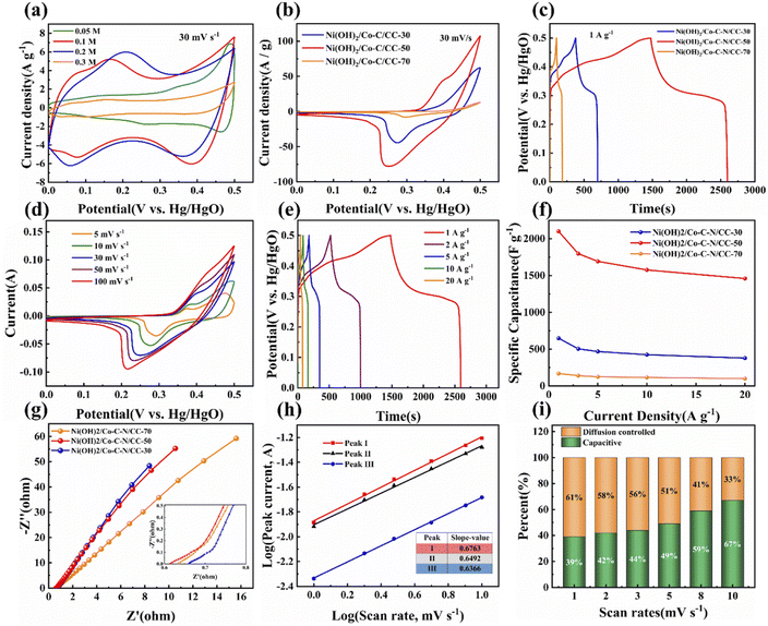
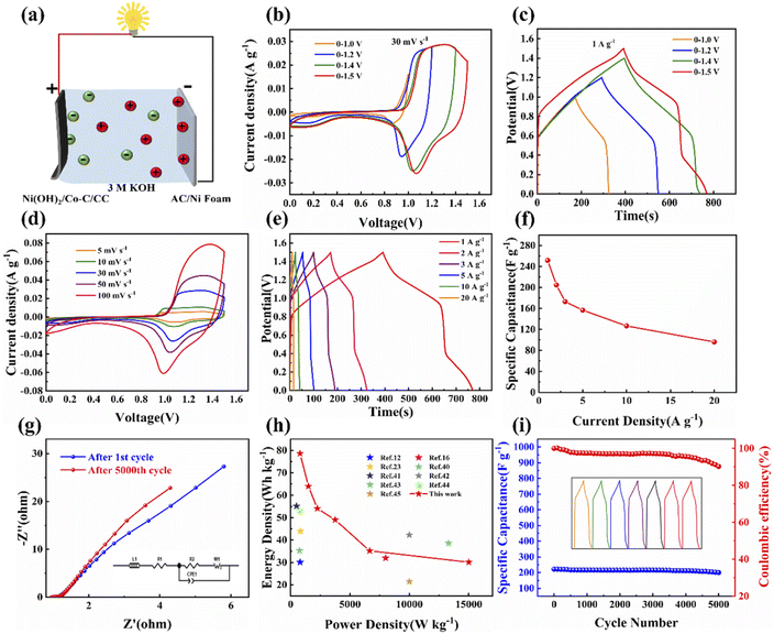
![[thin space (1/6-em)]](https://www.rsc.org/images/entities/char_2009.gif) 000th cycles of ASC, the inset is the equivalent circuit diagram. (h) Ragone plot of ASC. (i) Cycle stability at 10 A g−1 up to 5000 times charge and discharge of the ASC.
000th cycles of ASC, the inset is the equivalent circuit diagram. (h) Ragone plot of ASC. (i) Cycle stability at 10 A g−1 up to 5000 times charge and discharge of the ASC.