 Open Access Article
Impact of fluorination on the energy level alignment of an FnZnPc/MAPbI3 interface†
Elham
Oleiki
 a,
Saqib
Javaid
ab and
Geunsik
Lee
 *a
*a
aDepartment of Chemistry, Ulsan National Institute of Science and Technology (UNIST), Ulsan 44919, Republic of Korea. E-mail: gslee@unist.ac.kr
bMMSG, Theoretical Physics Division, PINSTECH, P.O. Nilore, Islamabad, Pakistan
First published on 12th October 2022
Abstract
We have studied interactions at an interface between a Methylammonium Lead Iodide (MAPbI3) surface and zinc-phthalocyanine molecules with F substituting peripheral H (FnZnPc; n = 4, 8, 12, and 16) by employing hybrid density functional theory (DFT) based simulations. These calculations show that FnZnPc molecules form a stable interface with MAPbI3, whose binding strength is comparable to that of the un-substituted (ZnPc) case. As a consequence of fluorination, an increase in the ionization potential/electron affinity (i.e., a systematic lowering of molecular energy levels), as well as interfacial charge transfer, is observed whose magnitude depends upon the degree of fluorination. In contrast to the common belief of unfavorable hole transfer for excessive fluorination, our work unveils that the valence band offset remains favorable for all ranges of substitution (n); thus, hole transfer from MAPbI3 to FnZnPc is facilitated while the electron transfer process is suppressed. This unusual behavior originates from the intermolecular interaction and substrate-to-molecule electron transfer at the heterojunction, which gradually suppresses the downward shift of FnZnPc energy levels by increasing the value of n. Given the beneficial impacts of fluorination, such as hydrophobicity, our work provides valuable insight for exploiting stable FnZnPc towards high-efficiency perovskite solar cells.
Introduction
Within hybrid perovskite solar cells, searching for cheap, stable and efficient hole transport materials is one of the critical research areas.1–3 At the moment, spiro-OMeTAD is commonly used as a hole transport layer (HTL).4,5 However, spiro-OMeTAD is expensive and unstable under hot and humid conditions.6 Thus, replacing spiro-OMeTAD is the key to developing durable and affordable solar cell technology. In this regards, metal-phthalocyanine molecules (MPc; M = 3d metal and Pc = N8C32H16) are thermally stable and relatively cheap, and can easily be grown into ordered thin films.7,8 Therefore, MPc molecules are widely used in organic solar cells as a donor material.9 Previous studies have confirmed that MPc can readily be utilized as a HTL with efficiency approaching ∼20%.10–12 Later, DFT based calculations further elucidated the interface electronic structure, where a suitable energy level alignment for hole transfer was found for face-on orientation.13,14Recently, it has been shown that halogenated molecular materials offer an excellent choice as a hole selective layer or HTL.1,2,15,16 Halogenation allows for efficient interfacial charge (hole) transfer via tailoring favorable energy level alignment. Moreover, the presence of halogen bonds at the interface passivates surface/interface defects, which in turn suppresses the recombination and thus improves the device stability. The halogenation of MPc can also be performed by substituting peripheral H atoms with fluorine (F), resulting in fluorinated metal-phthalocyanine.17,18 The F concentration (i.e., F/H ratio) within the MPc molecule can be readily controlled (i.e., FnMPc; n = 1–16), which facilitates suitable energy level tuning for the perspective applications.19 Indeed, FnMPc is employed extensively for different applications such as gas sensing and molecular electronics/spintronics.20–22 The integration of FnMPc within a perovskite solar cell can be very advantageous; FnMPc contains a highly hydrophobic C–F bond, which will impede the well-known moisture-related degradation of MAPbI3.23,24 Furthermore, as shown previously, the presence of F (via C–F bond within fluorinated graphene) at the interface can help to passivate the grain and surface defects of MAPbI3, thus improving the device performance and stability.25 This approach has recently been validated experimentally in the case of structurally similar porphyrin molecules, where fluorination significantly enhanced the stability and efficiency of photovoltaic devices.16 However, the utilization of FnMPc within hybrid solar cells is contingent upon suitable energy level alignment with MAPbI3 for an efficient charge separation process.
In this work, we have studied an interface between the MAPbI3 surface and fluorinated Zn-phthalocyanine (FnZnPc) by employing DFT based simulations. Specifically, four different degrees of fluorinations are investigated, i.e., F4ZnPc, F8ZnPc, F12ZnPc, and (fully fluorinated) F16ZnPc. These calculations show that despite lowering molecular energy levels due to fluorination, all the fluorinated compounds including F16ZnPc exhibit an interfacial energy level alignment suitable for hole transfer (and electron blockage) from MAPbI3 to FnZnPc.
Computational methods
All DFT calculations have been performed by employing the VASP suite, which is based on the plane wave pseudopotential approach.26 Generalized gradient approximation (GGA) within PBE parameterization was utilized as an exchange correlation functional.27 Furthermore, van der Waals (vdW) interactions were incorporated by adding dispersion correction to the total energy and forces by employing the Tkatchenko and Scheffler (TS) approach.28 The electronic structure and band gaps were further improved by utilizing the HSE06 hybrid functional including spin–orbit coupling,29 which is necessary for correct estimation of the MAPbI3 electronic structure.To model the MAPbI3 surface, a room temperature tetragonal phase is considered with experimentally determined lattice parameters, i.e., a = b = 8.856 Å and c = 12.65 Å.30 Specifically, an energetically optimum MAPbI3 (001) surface was used with a plane periodicity of 2 × 2 and having PbI2 termination.31,32 A vacuum layer of ∼15 Å was provided to avoid spurious interactions between the periodic images. The kinetic energy cutoff was set to 400 eV, while convergence criteria of 10−5 eV and 0.015 eV Å−1 were employed for energies and forces, respectively. A single Γ-point is used for k-point sampling, providing converged results for the electronic structure.14 The binding energy (EB) is defined as:
| EB = E(MAPbI3) + E(FnZnPc) − E(MAPbI3/FnZnPc) | (1) |
Results and discussion
Table 1 describes the adsorption properties of FnZnPc on the MAPbI3 surface, namely, the adsorption site, adsorption distance, and binding energy as a function of the fluorination level. For adsorption sites, three high symmetry positions are considered, which are referenced with respect to the position of the Zn atom on the MAPbI3 surface, i.e., Pb top (Pbtop), I top (Itop), and bridge position between the I and Pb atoms of MAPbI3. For all FnZnPc molecules, Itop is found to be the energetically optimum adsorption position with an adsorption energy of 2.4–2.6 eV (Table 1). We note that the energetic difference between I top and bridge positions is rather small, though this difference is significantly larger for optimum I top and Pb top positions (Table S1†). This is in contrast to the case of unsubstituted ZnPc, where differences between all adsorption positions were rather small and their energies were comparable.14 Furthermore, a gradual reduction in the molecule-surface separation is observed with fluorination; the adsorption distance for F16ZnPc is 2.84 Å as compared to 2.98 Å for ZnPc. However, fluorination does not bring about a significant variation to the binding energies in comparison to that of unsubstituted ZnPc, whose binding energy was about 2.5–2.6 eV.14| Site | d (Å) | E B (eV) | |
|---|---|---|---|
| ZnPc | Itop/Pbtop | 2.98 | 2.54 |
| F4ZnPc | Itop | 2.91 | 2.50 |
| F8ZnPc | Itop | 2.89 | 2.40 |
| F12ZnPc | Itop | 2.84 | 2.62 |
| F16ZnPc | Itop | 2.84 | 2.46 |
The adsorption geometry is further elaborated in Fig. 1, which schematically depicts F16ZnPc adsorption on the MAPbI3 Itop position. As highlighted in previous work,13,14 the planar conformation of unsubstituted ZnPc is significantly distorted on the MAPbI3 surface. In particular, peripheral H atoms move towards the surface such that a large vertical downshift of 0.45 Å is observed for H with respect to Zn. In contrast, this vertical distortion is much less pronounced in FnZnPc. For example, the maximum vertical distance between peripheral F and Zn is reduced to 0.16 Å for F16ZnPc. Nevertheless, the fluorinated case has greater distortion energy of the adsorbate or substrate due to the adsorbate–substrate coupling with respect to the separated equilibrium structure (eqn. S(1)), where the total distortion energy is calculated to be 0.46 eV and 0.20 eV for F16ZnPc/MAPbI3 and ZnPc/MAPbI3, respectively (Table S2†). Meanwhile, a gradual increase in charge transfer from MAPbI3 to FnZnPc is observed as the number of fluorine atoms increases. Specifically, a charge transfer of ∼0.18, 0.25, 0.29, and 0.34 e is observed for F4ZnPc, F8ZnPc, F12ZnPc and F16ZnPc, respectively, according to Bader charge analysis, while the magnitude of interfacial charge transfer is much smaller (∼0.03 or 0.10 e) for ZnPc/MAPbI3.13 This gradual increase of charge transfer with fluorination is associated with the higher electronegativity of F than H. Such charge transfer from the substrate to F16ZnPc could give rise to stronger electrostatic attraction between them with respect to the case without fluorination. However, upon fluorination, the electrostatic energy gain is impeded by a greater distortion energy (∼0.26 eV) as there was no significant difference in the calculated adsorption energies of F16ZnPc and ZnPc.
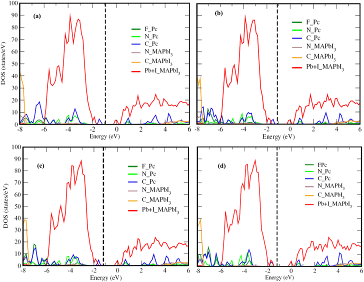
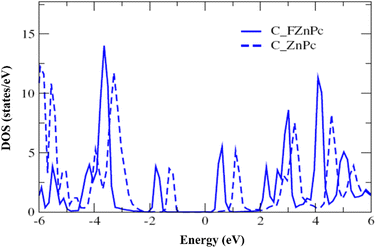
Fig. 2 presents the electronic structure of the FnZnPc/MAPbI3 interface, where the partial density of states (PDOS) is depicted as a function of the fluorination level. Overall, the electronic structure of MAPbI3 and FnZnPc does not seem to vary significantly due to interfacial interactions. This is understandable since direct hybridization between FnZnPc and MAPbI3 is relatively weak as discussed above. Nevertheless, an important trend is observed; a gradual downward shift of the PDOS of FnZnPc with increasing n is observed with respect to that of MAPbI3. Indeed, going from F4ZnPC to F16ZnPc, both the HOMO and LUMO of phthalocyanine molecules (which are dominated by C atoms) are pushed to lower energies by ∼0.45 eV. This effect is further demonstrated in Fig. 3, where the molecular C PDOSs are plotted together for F16ZnPc/MAPbI3 and ZnPc/MAPbI3 such that their vacuum levels are aligned. Evidently, both the HOMO and LUMO of F16ZnPc are shifted downward by ∼0.55 eV compared to that of ZnPc.
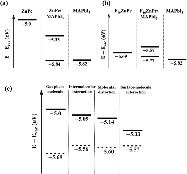
The attachment of an electron withdrawing element like F in place of H is expected to lower both the HOMO and LUMO resulting in an increase in both the ionization potential and electron affinity, as observed in Fig. 2 and 3.33 Indeed, fluorination is used to induce n-type transport within phthalocyanine molecules, which otherwise exhibit p-type behavior.17 The key impact of the environmental coupling (i.e., underlying MAPbI3 surface) is a noticeable reduction in this downward shift of energy levels. For example, the HOMO level shifts down by ∼0.9 eV from bare ZnPc to bare F16ZnPc, which is reduced to ∼0.55 eV after adsorption on the MAPbI3 surface. This reduction is likely to eliminate the concern of too much fluorination causing an FnZnPc HOMO level lying below the valence band maximum (VBM) of MAPbI3. The origin of such advantageous properties is studied with additional PBE calculations for the environmental effect on the molecular HOMO level. As shown in Fig. 4a, the energy level of the ZnPc HOMO is calculated to be −5.0 eV with respect to the vacuum level for the isolated case, whereas it is −5.33 eV for the adsorbed case on MAPbI3, and thus the ZnPc HOMO level is lowered by 0.33 eV upon adsorption. In addition, for ZnPc/MAPbI3, the second highest occupied orbital is from the substrate VBM and its energy level of −5.84 eV is very close to that of the pristine MAPbI3 surface (−5.82 eV). Similar results for F16ZnPc are shown in Fig. 4b. One can see that the molecular HOMO level rises upon adsorption from −5.69 to −5.57 eV; thus, it still remains above the substrate VBM (−5.77 eV). Hence our PBE results in Fig. 4a and b agree qualitatively well with the HSE06 results in Fig. 2 and 3, namely the downward shift of the ZnPc HOMO level upon fluorination is suppressed when the molecules are adsorbed.
We attribute the main reason to intermolecular and surface-molecular electrostatic interactions. Fig. 4c shows the HOMO levels of ZnPc (solid) and F16ZnPc (dashed) additionally for two intermediate hypothetical environments displayed between the isolated (gas phase molecule at left most) and the adsorbed case (surface–molecule interaction at right most). For the first environment checking the intermolecular interaction, we arranged the gas phase ZnPc or F16ZnPc molecules into a square lattice, where the lattice constant is chosen such that the intermolecular distance (Fig. S2†) is equal to that of the adsorbed molecules (Fig. 1). From Fig. 4c, one can see that the lateral molecule–molecule interaction lowers or raises the HOMO level for ZnPc or F16ZnPc, respectively, with respect to the isolated case. This opposite trend is caused by the positive (+28.8 ea02) and negative (−36.0 ea02) molecular quadrupole moments34 in the case of hydrogen and fluorine as peripheral species. We note that similar intermediate behavior is also expected if different (e.g. axisymmetric) molecular structures are used for partially fluorinated molecules (Table S3, Fig. S3, and S4†). The second environment additionally includes the molecule distortion caused by the interaction with the substrate. We note that the surface PbI2 layer has −0.98 e Bader charge, and thus relatively positive peripheral hydrogen atoms of ZnPc or central atoms including Zn of F16ZnPc tilt down to the substrate. Such slight derivation from the perfect planar shape makes the HOMO level further lower for two cases, as shown in the third panel indicated by molecular distortion in Fig. 4c. Finally, the presence of the substrate turns out to lower the HOMO level significantly for ZnPc; whereas it makes it a little higher for F16ZnPc, mainly due to repulsive potential from additional electrons transferred from the substrate to the molecule. The magnitude of the HOMO level downward shift is in the order of F4ZnPc > F8ZnPc > F12ZnPc (Fig. S5†).
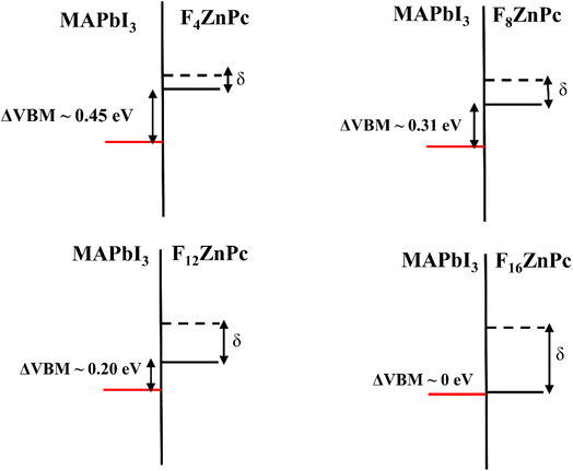
Based on the electronic structure discussed above, Fig. 5 depicts the interfacial energy level alignment between the VBM of MAPbI3 and the HOMO of FnZnPc, which is important for understanding the impact of fluorination on the charge (hole/electron) transfer process. For comparison, the corresponding HOMO level of unsubstituted ZnPc is also shown. As shown in Fig. 3, the ionization potential of FnZnPc increases due to fluorination. Most crucially, despite the downward shift of the HOMO, the energy level alignment remains favorable for hole transfer from MAPbI3 to FnZnPc since the molecular HOMO level is placed above the VBM of MAPbI3. In particular, a sizeable energy level offset (ΔVBM) is present for F4ZnPc, F8ZnPc, and F12ZnPc, which should facilitate the interfacial hole transfer. However, for the fully fluorination case (F16ZnPc), the band offset is almost zero. This means that the hole transfer process will be feasible though not necessarily efficient.
These findings clearly show that the adsorption of FnZnPc on MAPbI3 leads to the formation of a stable interface, whose adsorption energy is comparable to that of its unsubstituted counterpart, i.e., ZnPc/MAPbI3 interface. The presence of the hydrophobic C–F bonds at the FnZnPc/MAPbI3 interface will impede the moisture-related degradation of MAPbI3 and may also help to passivate surface defects, as is shown for other halogenated molecules.24 Moreover, the electronic structure (Fig. 3) and interfacial valence level alignment (Fig. 5) demonstrate that the hole transfer from MAPbI3 to FnZnPc is feasible, while the alignment of conduction bands ensures electron blockage. In particular, for a relatively low substitution level of F (e.g., F4ZnPc), the valence band offset is appreciable, which should facilitate the hole transfer process while inhibiting the electron transfer simultaneously. It should be further pointed out that the hole mobility of F4ZnPc has the same order of magnitude as that of ZnPc in the bulk heterojunction system, while an increase in ionization potential due to fluorination may increase the open circuit voltage (Voc), which will improve the overall efficiency of the device.16,21 The comparable hole mobilities of ZnPc and FnZnPc are in agreement with our band structure calculations (Fig. S6†).
Finally, as highlighted in Fig. 5, the HOMO of unsubstituted ZnPc lies at higher energy than that of FnZnPc such that the hole transfer is feasible from FnZnPc to ZnPc. This means that besides the hole transport medium, a heterojunction (MAPbI3/FnZnPc/ZnPc) can be formed, where a protective and hole selective interface layer of FnZnPc can be deposited between MAPbI3 and a usual hole transport layer such as ZnPc. Also, from an experimental report,35 the degree of crystallinity is lowered for fluorinated ZnPc compared to that of unsubstituted ZnPc and the roughness of F4ZnPc is two times smaller than that of ZnPc, and hence the junction interface will become smooth due to the presence of FnZnPc towards a better electronic contact. There might be a deteriorating effect like carrier trapping caused by the FnZnPc/ZnPc interface, but the impact is not significant and rather provides a way of tuning the ionization energy continuously.34,36 Overall, the presence of FnZnPc as an interlayer or hole transport medium will improve the stability of solar cell devices against moisture and the hole extraction efficiency.
Conclusions
We have studied interactions at an FnZnPc/MAPbI3 interface by employing DFT based simulations. The results show that FnZnPc forms a stable interface with the MAPbI3 surface with binding energies comparable to that of the unsubstituted case. The alignment between the MAPbI3 VBM and FnZnPc HOMO at the interface promotes hole transfer from MAPbI3 to FnZnPc, while impeding the deleterious electron transfer process simultaneously. These results suggest that incorporating FnZnPc into photovoltaic devices as a protective interlayer or as a hole transport medium should significantly improve the device stability without any noticeable reduction in the efficacy, particularly for lower level F substitution (e.g., F4ZnPc and F8ZnPc).Conflicts of interest
There are no conflicts to declare.Acknowledgements
This work was supported by the National Research Foundation of Korea (NRF) grant funded by the Korean government (MSIT) (No. NRF-2021M3H4A1A02055684) and Pakistan Atomic Energy commission. We also acknowledge the support of MIS at PINSTECH, and PIEAS, Islamabad, regarding providing the computational resources. GL acknowledges support of Samsung Electronics Co. through Industry-University Cooperation Project (IO221012-02835-01).References
- A. Al-Ashouri, E. Köhnen, B. Li, A. Magomedov, H. Hempel, P. Caprioglio, J. A. Márquez, A. B. Morales Vilches, E. Kasparavicius, J. A. Smith, N. Phung, D. Menzel, M. Grischek, L. Kegelmann, D. Skroblin, C. Gollwitzer, T. Malinauskas, M. Jošt, G. Matič, B. Rech, R. Schlatmann, M. Topič, L. Korte, A. Abate, B. Stannowski, D. Neher, M. Stolterfoht, T. Unold, V. Getautis and S. Albrecht, Science, 2020, 370, 1300–1309 CrossRef CAS PubMed.
- N. J. Jeon, H. Na, E. H. Jung, T.-Y. Yang, Y. G. Lee, G. Kim, H.-W. Shin, S. Il Seok, J. Lee and J. Seo, Nat. Energy, 2018, 3, 682–689 CrossRef CAS.
- L. Canil, J. Salunke, Q. Wang, M. Liu, H. Köbler, M. Flatken, L. Gregori, D. Meggiolaro, D. Ricciarelli, F. De Angelis, M. Stolterfoht, D. Neher, A. Priimagi, P. Vivo and A. Abate, Adv. Energy Mater., 2021, 11, 2101553 CrossRef CAS.
- D. Meggiolaro, E. Mosconi, A. H. Proppe, R. Quintero-Bermudez, S. O. Kelley, E. H. Sargent and F. De Angelis, ACS Energy Lett., 2019, 4, 2181–2184 CrossRef CAS.
- Y. Li, H. Li, C. Zhong, G. Sini and J.-L. Brédas, npj Flexible Electron., 2017, 1, 2 CrossRef.
- Y. Matsuo, K. Ogumi, I. Jeon, H. Wang and T. Nakagawa, RSC Adv., 2020, 10, 32678–32689 RSC.
- M. Grobosch, C. Schmidt, R. Kraus and M. Knupfer, Org. Electron., 2010, 11, 1483–1488 CrossRef CAS.
- H. Yamada, T. Shimada and A. Koma, J. Chem. Phys., 1998, 108, 10256–10261 CrossRef CAS.
- A. A. A. Torimtubun, J. Follana-Berná, J. G. Sánchez, J. Pallarès, Á. Sastre-Santos and L. F. Marsal, ACS Appl. Energy Mater., 2021, 4, 5201–5211 CrossRef CAS.
- G. Yang, Y.-L. Wang, J.-J. Xu, H.-W. Lei, C. Chen, H.-Q. Shan, X.-Y. Liu, Z.-X. Xu and G.-J. Fang, Nano Energy, 2017, 31, 322–330 CrossRef CAS.
- Y. C. Kim, T.-Y. Yang, N. J. Jeon, J. Im, S. Jang, T. J. Shin, H.-W. Shin, S. Kim, E. Lee, S. Kim, J. H. Noh, S. I. Seok and J. Seo, Energy Environ. Sci., 2017, 10, 2109–2116 RSC.
- T. Duong, J. Peng, D. Walter, J. Xiang, H. Shen, D. Chugh, M. Lockrey, D. Zhong, J. Li, K. Weber, T. P. White and K. R. Catchpole, ACS Energy Lett., 2018, 3, 2441–2448 CrossRef CAS.
- H. Qin, L. Xu and D. Zhong, J. Phys. Chem. C, 2020, 124, 5167–5173 CrossRef CAS.
- S. Javaid and G. Lee, RSC Adv., 2021, 11, 31776–31782 RSC.
- A. Ullah, K. H. Park, H. D. Nguyen, Y. Siddique, S. F. A. Shah, H. Tran, S. Park, S. I. Lee, K. Lee, C. Han, K. Kim, S. Ahn, I. Jeong, Y. S. Park and S. Hong, Adv. Energy Mater., 2022, 12, 2103175 CrossRef CAS.
- R. Azmi, U.-H. Lee, F. T. A. Wibowo, S. H. Eom, S. C. Yoon, S.-Y. Jang and I. H. Jung, ACS Appl. Mater. Interfaces, 2018, 10, 35404–35410 CrossRef CAS PubMed.
- K. Shati, S. Javaid, R. T. A. Khan and M. J. Akhtar, J. Magn. Magn. Mater., 2020, 494, 165775 CrossRef CAS.
- S. Lindner, M. Knupfer, R. Friedrich, T. Hahn and J. Kortus, Phys. Rev. Lett., 2012, 109, 027601 CrossRef PubMed.
- A. Varotto, C.-Y. Nam, I. Radivojevic, J. P. C. Tomé, J. A. S. Cavaleiro, C. T. Black and C. M. Drain, J. Am. Chem. Soc., 2010, 132, 2552–2554 CrossRef CAS PubMed.
- P. F. Siles, T. Hahn, G. Salvan, M. Knupfer, F. Zhu, D. R. T. Zahn and O. G. Schmidt, Nanoscale, 2016, 8, 8607–8617 RSC.
- J. Meiss, A. Merten, M. Hein, C. Schuenemann, S. Schäfer, M. Tietze, C. Uhrich, M. Pfeiffer, K. Leo and M. Riede, Adv. Funct. Mater., 2012, 22, 405–414 CrossRef CAS.
- D. Klyamer, A. Sukhikh, S. Gromilov, P. Krasnov and T. Basova, Sensors, 2018, 18, 2141 CrossRef PubMed.
- G.-H. Kim, H. Jang, Y. J. Yoon, J. Jeong, S. Y. Park, B. Walker, I.-Y. Jeon, Y. Jo, H. Yoon, M. Kim, J.-B. Baek, D. S. Kim and J. Y. Kim, Nano Lett., 2017, 17, 6385–6390 CrossRef CAS PubMed.
- S. Javaid, C. W. Myung, S. Pourasad, B. Rakshit, K. S. Kim and G. Lee, J. Mater. Chem. A, 2018, 6, 18635–18640 RSC.
- L. Yang, Y. Li, L. Wang, Y. Pei, Z. Wang, Y. Zhang, H. Lin and X. Li, ACS Appl. Mater. Interfaces, 2020, 12, 22992–23001 CrossRef CAS PubMed.
- G. Kresse and J. Furthmüller, Comput. Mater. Sci., 1996, 6, 15–50 CrossRef CAS.
- J. P. Perdew, K. Burke and M. Ernzerhof, Phys. Rev. Lett., 1996, 77, 3865–3868 CrossRef CAS PubMed.
- A. Tkatchenko and M. Scheffler, Phys. Rev. Lett., 2009, 102, 073005 CrossRef PubMed.
- A. V. Krukau, O. A. Vydrov, A. F. Izmaylov and G. E. Scuseria, J. Chem. Phys., 2006, 125, 224106 CrossRef PubMed.
- S. T. A. G. Melissen, F. Labat, P. Sautet and T. Le Bahers, Phys. Chem. Chem. Phys., 2015, 17, 2199–2209 RSC.
- G. Volonakis and F. Giustino, J. Phys. Chem. Lett., 2015, 6, 2496–2502 CrossRef CAS PubMed.
- J. H. Heo, S. H. Im, J. H. Noh, T. N. Mandal, C.-S. Lim, J. A. Chang, Y. H. Lee, H. Kim, A. Sarkar, M. K. Nazeeruddin, M. Grätzel and S. Il Seok, Nat. Photonics, 2013, 7, 486–491 CrossRef CAS.
- J. E. Anthony, A. Facchetti, M. Heeney, S. R. Marder and X. Zhan, Adv. Mater., 2010, 22, 3876–3892 CrossRef CAS PubMed.
- M. Schwarze, K. S. Schellhammer, K. Ortstein, J. Benduhn, C. Gaul, A. Hinderhofer, L. Perdigón Toro, R. Scholz, J. Kublitski, S. Roland, M. Lau, C. Poelking, D. Andrienko, G. Cuniberti, F. Schreiber, D. Neher, K. Vandewal, F. Ortmann and K. Leo, Nat. Commun., 2019, 10, 2466 CrossRef PubMed.
- D. D. Klyamer, A. S. Sukhikh, S. A. Gromilov, V. N. Kruchinin, E. V. Spesivtsev, A. K. Hassan and T. V. Basova, Macroheterocycles, 2018, 11, 304–311 CrossRef CAS.
- M. Schwarze, W. Tress, B. Beyer, F. Gao, R. Scholz, C. Poelking, K. Ortstein, A. A. Günther, D. Kasemann, D. Andrienko and K. Leo, Science, 2016, 352, 1446–1449 CrossRef CAS PubMed.
Footnote |
| † Electronic supplementary information (ESI) available. See DOI: https://doi.org/10.1039/d2na00582d |
| This journal is © The Royal Society of Chemistry 2022 |


