Enhanced air filtration performances by coating aramid nanofibres on a melt-blown nonwoven†
Kangli
Xu‡
 a,
Lei
Zhan‡
a,
Rui
Yan
a,
Qinfei
Ke
a,
Lei
Zhan‡
a,
Rui
Yan
a,
Qinfei
Ke
 a,
Anlin
Yin
*b and
Chen
Huang
 *a
*a
aEngineering Research Center of Technical Textiles, Ministry of Education, College of Textiles, Donghua University, Shanghai 201620, China. E-mail: hc@dhu.edu.cn
bCollege of Material and Textile Engineering, Nanotechnology Research Institute, Jiaxing University, Jiaxing, 314001, China. E-mail: yinanlin@126.com
First published on 2nd December 2021
Abstract
Nanofibre membranes with a small diameter and a large specific surface area are widely used in the filtration field due to their small pore size and high porosity. To date, aramid nanofibres (ANFs) have received extensive research interest because of their high stiffness and excellent temperature resistance. However, the preparation of ANFs usually takes a long time, which greatly hampers the practical application of these fibres. Herein, we report the preparation of ANFs by a modified deprotonation method at elevated temperature. Owing to the increase of temperature, the preparation cycle of ANFs was shortened to 8 hours. The resulting ANF dispersion was further coated on a polypropylene melt-blown nonwoven to form a composite nonwoven filter. With the submicron porous structure, the filtration efficiency, pressure drop and quality factor of the filter were 95.61%, 38.22 Pa and 0.082 Pa−1, respectively. Compared to the pristine nonwoven, the filtration, mechanical, and heat insulation properties of the composite filter were also significantly improved. This work may offer a simple and efficient way for enhancing the air filtration performances of current filters.
1. Introduction
Poly(p-phenylene terephthalamide) (PPTA) fibres, generally known as Kevlar® or Twaron®, are well acknowledged for their high strength, high modulus, high temperature resistance and corrosion resistance.1–3 These superior features are largely attributed to the highly crystallized and oriented macromolecular structure of PPTA, i.e., the regular arrangement of the rigid carbon chain with axial π–π conjugation and transverse hydrogen bonding force.4,5 However, due to the high crystallinity and the chemically inert surface of PPTA, the interface between neighboring fibres and the entanglement of fibres in matrix structures are relatively weak, thus limiting the application of PPTA fibres in polymeric composites.6,7To tackle the above problem, aramid nanofibres (ANFs) with a large aspect ratio, high specific surface area (SSA) and chemical activity have been developed. ANFs are derived from PPTA microfibres, and have been proved effective for improving the low interfacial strength between PPTA fibres and other materials.8,9 In 2011, Kotov et al. first proposed a deprotonation method that could obtain ANFs with a length of 5–10 μm and a diameter of 3–30 nm in a KOH/DMSO solvent mixture.10 Besides inheriting the intrinsic properties of PPTA microfibres, these nanofibres were regarded as active building blocks on account of their ultrafine diameter, superior size controllability and easy film formation. Until now, a lot of composite structures containing ANFs have been designed and constructed via layer-by-layer self-assembly (LBL), crosslinking based on physical/chemical interactions such as hydrogen bonding, π–π conjugate accumulation and electrostatic adsorption.11 The ANFs inside these composites were proved to be able to satisfy a variety of applications, including composite reinforcement,12–16 interfacial adhesives,17 battery separators,18–20 adsorption and filtration media,21–24 electrical insulation1,25,26 and flexible electrodes.27–30 The ultrafine diameter of ANFs also enables them to readily interweave into membranes with a small pore size but high porosity,31 which in principle should be highly desirable in the field of filtration.
Despite the successful fabrication of aramid fibres on the nanometer scale, so far, most of the ANF-based materials have been limited in the laboratory, since it takes a long period (usually 7–10 days) for generating ANFs. In order to improve the preparation efficiency of traditional methods, Koo et al. proposed a direct monomer-to-ANF synthesis strategy by deprotonating the as-synthesized low-molecular-weight PPTA intermediate in a KOH/DMSO/co-solvent, and the preparation time could be reduced to 15 h.32 Yang et al. proposed a proton donor-assisted deprotonation method by strictly controlling the amount of water (proton donor) added into the PPTA/KOH/DMSO system. With the existence of water molecules, ANFs could be partially reprotonated, leading to a lower inherent viscosity of ANFs. When the volume ratio of water and solvent was 1![[thin space (1/6-em)]](https://www.rsc.org/images/entities/char_2009.gif) :
:![[thin space (1/6-em)]](https://www.rsc.org/images/entities/char_2009.gif) 25, the preparation time could be reduced to 4 h.33 While these two methods greatly shortened the preparation time, specific conditions such as the restricted molecular weight of PPTA and strict volume ratio of water to solvent were required, and the processes were relatively complex.
25, the preparation time could be reduced to 4 h.33 While these two methods greatly shortened the preparation time, specific conditions such as the restricted molecular weight of PPTA and strict volume ratio of water to solvent were required, and the processes were relatively complex.
Herein, we investigated the deprotonation behavior for ANF preparation under different temperature conditions, and proved that the preparation cycle of ANFs could be dramatically shortened by simply elevating the preparation temperature to 60 °C. The acquired ANF solution was then coated onto a melt-blown nonwoven using film casting apparatus. The structure, mechanical properties and thermal stability of the resultant composite nonwoven were tested, and the results showed that the coating of an ANF film could largely improve the filtration and overall performances of the pristine nonwoven, making it qualified for removing airborne pollutants.
2. Experimental section
2.1. Materials
PPTA fibres (Kevlar 29, with a diameter ∼15 μm) were obtained from DuPont (USA). Polypropylene (PP) melt-blown nonwovens (20 g m−2) were supplied by Xuancheng Guangneng Co. Ltd, China. Dimethyl sulfoxide (DMSO), potassium hydroxide (KOH) and anhydrous ethanol were purchased from Shanghai Lingfeng Chemical Reagents Co., Ltd, China. Unless specified, all solvents were used directly without further purification.2.2. Preparation of ANF/DMSO dispersion
PPTA fibres were soaked in anhydrous ethanol and sonicated for 1 hour to clean the surface oil. The fibres were then washed with deionized (DI) water and dried at 80 °C overnight. 1.5 g of KOH was first added to 500 mL of DMSO and stirred for 30 min at room temperature. 1.0 g of clean PPTA fibres was added to KOH/DMSO solution (with a concentration of 0.2%) and stirred at 20, 30, 40, 50 and 60 °C, respectively. The preparation time was recorded when a homogeneous, transparent and dark-red ANF/DMSO dispersion was obtained.2.3. Preparation of ANF film
A continuous sol–gel transformation method was employed to form an ANF film.34 5 mL of 0.2 wt% ANF/DMSO solution was scraped onto a clean glass plate with the blade distance of 50 μm to form an ANF/DMSO sol, which was then immersed in DI water for 12 h to achieve thorough solvent exchange. The obtained ANF film was then dried at 80 °C for 30 min. The ANF films produced with different solutions at the evaluated water bath temperature were named ANF-F/20 °C, ANF-F/30 °C, ANF-F/40 °C, ANF-F/50 °C and ANF-F/60 °C, respectively.2.4. Fabrication of the ANF/melt-blown composite nonwoven
ANF/melt-blown nonwoven composites with different blade distances (the distance between the bottom of the blade and the top of the melt-blown nonwoven) were obtained using an automatic film casting device with a working width of 20 cm.35 The liquid storage device added dropwise ANF dispersion (concentration = 0.2 wt%, prepared at 60 °C) onto the nonwoven surface at the rate of 5 mL s−1. The coating rate was 80 mm s−1, and the blade distances were set as 50, 100, 150 and 200 μm, respectively. Then the coated ANF/melt-blown nonwoven composite was immersed in DI water to achieve thorough solvent exchange and dried under an infrared lamp. The uncoated melt-blown nonwoven was used as a control.2.5. Characterization
The morphology of PPTA microfibres and ANFs was observed by field emission scanning electron microscopy (FE-SEM, Hitachi SU8010, Japan). The morphology of ANFs in DMSO solution was further imaged by transmission electron microscopy (TEM, JEOL JEM-2100, Japan). The ANF/DMSO dispersion with a concentration of 0.2% was diluted 50 times before being dripped onto the carbon-supported film. The acceleration voltage was 200 kV. To measure the diameter distribution of ANFs, 20 TEM images were obtained from different locations of each sample, after which 500 ANFs were randomly selected from these images and their diameters were counted using ImageJ software. The process of PPTA fiber dissolution was characterized using an ultraviolet visible near infrared spectrophotometer (UV-VIS(NIR), Lambda 35, Singapore) from 200 to 500 nm. Fourier transform infrared spectroscopy (FT-IR) of ANF films and ANF/melt-blown nonwoven composites was conducted using a Nicolet 6700 infrared spectrometer. X-ray diffraction (XRD) of ANF films was performed using a D/Max-2500 PC X-ray diffractometer (Rigaku Corporation, Japan). Raman spectra were acquired using a Raman system (inVia-Reflex, UK) with 532 nm excitation. Thermogravimetric analysis (TGA) was conducted using a thermal gravimetric analyzer (PerkinElmer TGA4000, Holland) from 30 to 800 °C with a heating rate of 10 °C min−1 under a nitrogen atmosphere. The thermal stability of ANF/melt-blown nonwoven composites (20 × 10 mm) was tested by placing the samples between slide glass and subjecting to tensile shear stress. The heating temperature was set at 160 and 170 °C, respectively. After heating for 1 hour, the shrinkage of the samples was measured both in the cross direction (CD) and machine direction (MD). The mechanical properties of the ANF film with a size of 40 × 10 mm were measured using a universal tensile tester (Darong YG(B)026h-500, China) with a tensile velocity of 10 mm min−1 at room temperature. The pore size and pore size distribution of ANF/melt-blown nonwovens were measured using a capillary flow porometer (CFP-1100AI, Porous Materials, Inc., USA). Nitrogen adsorption–desorption isotherms were measured at 77 K using a Micromeritics ASAP 2460 analyzer (Micromeritics Instruments, USA). The SSA was calculated by the Brunauer–Emmett–Teller (BET) method using the adsorption branch data in the relative pressure (P/P0) range from 0.0 to 1.0. Filtration performances were conducted using an automatic filter tester (Certi Test 8130, TSI, USA) with a filter holder with an effective area of 100 cm2. Solid sodium chloride solution (NaCl, 2 wt%) was employed to generate aerosol particles (mass median diameter = 260 nm and the geometric standard deviation of the particles was less than 1.83).36 Before testing, the aerosol generator was preheated for more than 30 minutes to ensure the accuracy of data. The filtration efficiency (η) could be calculated as follows:| η(%) = (1 − γ1/γ2) × 100% | (1) |
3. Results and discussion
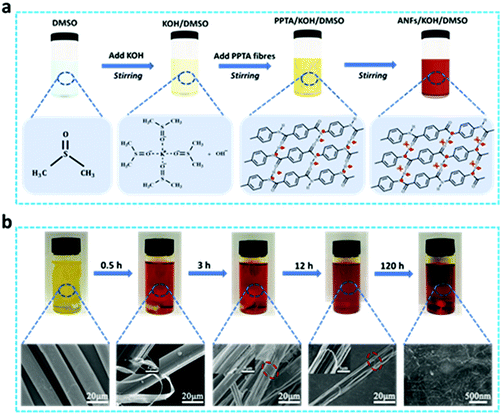
Ever since the demonstration that ANFs could be obtained by deprotonating PPTA fibres in KOH/DMSO solution at room temperature, these fibres have become emerging functional nanomaterials for environmental and energy purposes.38 However, a full preparation cycle of ANFs is time-consuming (up to 7 days). With the aim to shorten this preparation time, we further investigated the decomposition process and mechanism of PPTA fibres in KOH/DMSO. As shown in Fig. 1a, fibres were added after the full reaction of KOH with DMSO, and the reaction temperature was set at 20 °C. In pure DMSO, PPTA fibres could only be partially dissolved,39 while the mixture of KOH/DMSO could form a strong alkali system to facilitate the dissolution of PPTA fibres. Here DMSO became a polar aprotic solvent after the addition of KOH, and K+ was encapsulated in the center to stabilize the cation, making OH− a relatively free ion to improve the nucleophilicity. The KOH/DMSO system first extracted the mobile hydrogen from the amide groups to generate negatively charged polymer chains. The hydrogen bond networks among the PPTA polymer chains were then broken apart due to the electrostatic repulsion, making PPTA microfibres split into nanofibres. Finally, a stable ANF/DMSO dispersion was formed under the balance of electrostatic repulsion, π–π stacking and van der Waals forces.40 The formation process and the potential mechanism of ANFs were confirmed using Raman scattering patterns (Fig. S1†), and the absorption peaks at 1571 cm−1 (C–N and N–H) and 1647 cm−1 (C![[double bond, length as m-dash]](https://www.rsc.org/images/entities/char_e001.gif) O, C–N and N–H) were weakened during the fibrillation process. The peak intensity at 1571 cm−1 dramatically decreased over time, and this peak eventually disappeared after 120 h, which was probably because of the extraction of hydrogen from the amide groups. Accompanied by the disappearance of this peak, ANFs were fully generated.
O, C–N and N–H) were weakened during the fibrillation process. The peak intensity at 1571 cm−1 dramatically decreased over time, and this peak eventually disappeared after 120 h, which was probably because of the extraction of hydrogen from the amide groups. Accompanied by the disappearance of this peak, ANFs were fully generated.
The color change of the solution and the corresponding SEM images over time are shown in Fig. 1b. When PPTA fibres were added to KOH/DMSO, the color of the whole system became notably darker within 30 min, proving that an early mixing of KOH/DMSO might accelerate the whole reaction process (Fig. S2†). As the reaction went on, the deprotonation degree of PPTA fibres increased, and the ANFs were formed. The color of the solution changed from yellow to orange, and a uniform, transparent, dark-red solution was formed after 120 hours. SEM images presented the changes in the fineness and length of PPTA fibres as the deprotonation reaction continued. The pristine PPTA fibres showed a smooth cylindrical microstructure, with an average diameter of ∼15 μm. In the process of dissolving PPTA fibres, the macroscopic fibres were decomposed into smaller ones step by step. The solvent vortex peeled the nanofibres off from PPTA microfibres soon after the beginning of the reaction. ANFs at this stage were all generated along the fibre axis. After 3 hours, a large area of grooves on the surface of PPTA fibres was observed, whilst in the middle of these grooves, a few ANFs were generated along the radial direction. This indicated that ANFs could be produced in both the radial and axial directions of the PPTA microfibres, and the solution penetrated the cracks and voids of microfibres to form grooves, thereby increasing the contact area and accelerating the speed of deprotonation.
After 12 h, the diameter of PPTA microfibres significantly decreased, whilst these fibres suffered severe radial fracture and broke into several parts during the continuous reaction and agitation. The mechanism for this lies in two aspects; on one hand, the shearing force caused the directional mutation of chain rigidity. In order to adapt to this change, the local tension of the fibre would lead to the fracture of the chain or even permanent deformation, which was expressed as the raised or shifted kink sections on the surface of PPTA fibres. Since these kink sections altered the axial direction of fibres, fibre fracture would be inevitable.41 On the other hand, PPTA fibres featured high anisotropy and low shear performance. When they were subjected to shearing force, the internal structure was easily damaged, and the orderly crystalline region would become loose, resulting in the radial fracture of the fibre. As the reaction went on, the core layer completely dissolved after 120 h, making ANFs disperse uniformly in the dispersion.
The process of dissolving PPTA fibres into ANFs could also be confirmed by the changes in the UV spectral absorbance of dispersion during the dissolution of PPTA fibres (Fig. S3†). The absorption peaks ranging from 325 to 335 nm were ascribed to the amide groups in PPTA fibres, and the absorption peaks at 400 nm were attributed to the deprotonated amide groups in ANFs. During the reaction progress, gradual changes were observed in the UV absorbance curves of ANF/DMSO dispersion, and the peak intensity at 400 nm gradually increased. After 120 h, this peak no longer changed, indicating the endpoint of the deprotonation reaction and the complete generation of ANFs.
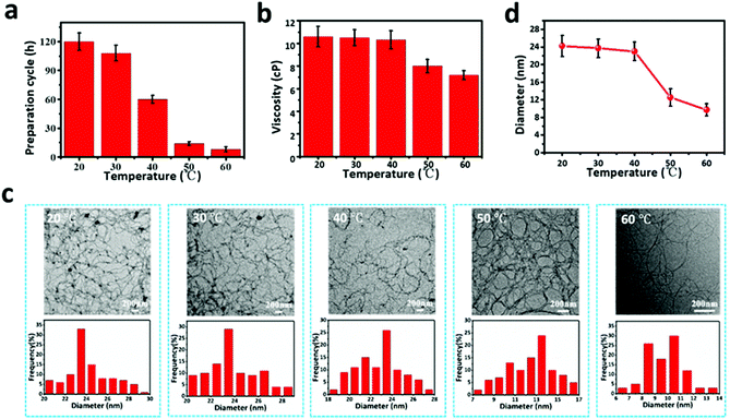
As mentioned above, this study, with the ultimate goal to improve the filtration performances of filters containing ANFs, entails the preparation of ANFs in an efficient manner. Therefore, the PPTA/DMSO system was placed at different temperatures for magnetic stirring. It is noteworthy that a slight increase of temperature could significantly accelerate the reaction speed and shorten the preparation cycle. As shown in Fig. 2a, when the temperature reached 60 °C, the time for achieving uniform and transparent ANF dispersion greatly decreased from 120 to 8 h. The viscosity of dispersion also decreased with the increase of temperature (Fig. 2b). The viscosity of ANF dispersion at 60 °C was 7.38 cP., while the viscosity at 20 °C was 10.6 cP., which was conducive to the following steps such as blade coating.
With the increase of temperature, OH− in the solution had more thermal energy, which could overcome a certain energy barrier and accelerate the movement or beating speed of the solvent between the molecular chains, making it easier for PPTA fibres to deprotonate in the KOH/DMSO system. When increasing the deprotonation degree, the negative charge density on the molecular chain of PPTA fibres increased, which enhanced the electrostatic repulsion between the chains and facilitated the generation of ANFs. The microstructure and morphology of ANFs are shown by the TEM images in Fig. 2c. In general, the distributions of ANFs in solution were uniform, regardless of the ambient temperature, whereas the diameter of ANFs differed with the change of temperature. According to the statistical results in Fig. 2d, the average diameter of ANFs at 20 °C was 24.2 ± 2.1 nm, and it remained constant until 40 °C. When the temperature was increased to 50 °C, however, the average diameter significantly decreased to 12.5 ± 2.0 nm, and it further decreased to 9.7 ± 1.4 nm at 60 °C. This phenomenon might also be used to explain the negative correlation between solution viscosity and reaction temperature. The increase of temperature led to a smaller diameter and molecular weight of ANFs, which consequently reduced the viscosity of ANF dispersion.
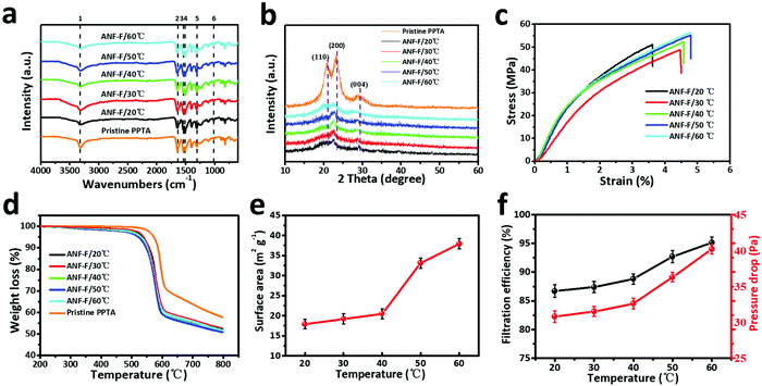
Moreover, ANFs are easy to self-assemble through strong hydrogen bonds by vacuum-assisted filtration (VAF) or layer-by-layer (LBL) deposition methods to form a transparent, strong, though, and thermally stable ANF film.42,43 In our work, the phase transformation method was used to form the ANF film. The chemical structure of the ANF film obtained at different temperatures was characterized and compared by FT-IR spectroscopy (Fig. 3a and Table S1†).44 The main vibration peaks of ANF films are the same as those of pristine PPTA fibres, indicating that the molecular structure of PPTA was not altered by the reaction or the increase of temperature. By contrast, the XRD pattern of ANFs differed obviously from that of pristine PPTA fibres (Fig. 3b). The broad peaks at 20.5°, 23.0° and 28.0° of pristine fibres correspond to the (110), (200) and (004) reflection planes, respectively.45 Although ANFs also had these peaks, the sharpness and intensity were much lower, indicating a lower crystallinity caused by the decrease of molecular weight.
The mechanical properties of the films composed of ANFs acquired at different temperatures are presented in Fig. 3c. By inheriting the high rigidity of PPTA fibres, all ANF films exhibited high stress but low strain, and the stress was up to 56.5 MPa. The increase of temperature has no significant influence on stress, but it slightly increased the strain. According to the mechanical results in Fig. 3c, we speculate that with the increase of temperature, the deprotonation degree was more thorough, resulting in a smaller fibre diameter and a more uniform distribution of ANFs that were conducive to the flexibility of the ANF film. In addition, ANFs with a smaller diameter intended to form a relatively dense structure, which effectively prevented the decrease of stress. The thermal stability of ANF films was further evaluated by TGA (Fig. 3d). The ANF films showed a rapid decrease in quality in the temperature range from 510 °C to 607 °C. Compared with PPTA microfibres, the starting weight loss temperature of the ANF film decreased by 40 °C, but it still possessed a high temperature resistance. These results demonstrated that the increase of preparation temperature barely changed the mechanical properties and the heat resistance of ANFs. Therefore, ANFs prepared via this method can still be used as building blocks for a lot of high performance materials.
The SSAs of ANF films prepared at different temperatures were measured using an ASAP 2460 analyzer, and all ANF films showed a large surface area (>15 m2 g−1, Fig. 3e). Increasing the temperature to no more than 40 °C would slightly increase the SSA of ANF films. However, when the temperature was increased to 50 °C, the SSA increased significantly to 33.1 m2 g−1, and it further increased to 37.9 m2 g−1 at 60 °C, which was in accordance with the reduced diameter of ANFs. The increase of SSA allowed the nonwoven composite to capture more solid particles, thus improving the filtration efficiency (Fig. 3f). However, with the increase of temperature, both the fibre diameter and inter-fibre pores became smaller, resulting in an inevitable increase of pressure drop.
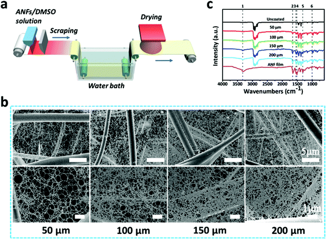
When used for filtration purposes, melt-blown nonwovens usually go through an electret treatment.46–49 This process enables the nonwovens to carry positive charges that can capture more particulate matters (PMs). Considering that PPTA and the resulting ANFs possess negative charges, we hypothesize that ANFs may be directly coated on melt-blown nonwovens to further enhance their filtration performances. Therefore, an automatic coating device was applied to coat ANF solution on the surface of a melt-blown nonwoven (Fig. 4a). Firstly, ANF/DMSO solution prepared at different temperatures was coated on melt-blown nonwovens, and their filtration performances were tested. As can be seen in Fig. S4,† the decease of fibre diameter was conductive to the improvement of filtration efficiency. However, the decease of diameter would also result in a more densely-packed film and thus the increase in pressure drop. Therefore, the quality factor (QF) was introduced to comprehensively evaluate the filtration performances of ANF/melt-blown nonwoven composites with different blade distances. The QF can be expressed as −ln(1 − η)/Δp, where η is the filtration efficiency and Δp is the pressure drop of the filter.50 At 60 °C, the filtration efficiency and pressure drop of the ANF/melt-blown nonwoven were 95.7% and 40.6 Pa, respectively, leading to the highest QF of 0.0775 Pa−1.
In order to achieve efficient and uniform coating, the solution was prepared at 60 °C and the blade distance was set at 50, 100, 150 and 200 μm. The SEM images of the corresponding ANF/melt-blown nonwoven composites are shown in Fig. 4b. The relatively small pore size of the melt-blown substrate (ranging from 5 to 17 μm, Fig. S5†) prevented the rapid infiltration of ANF solution, thus ensuring ANFs to deposit on the nonwoven surface. Upon exposure to air, a thin ANF film would be rapidly solidified due to the protonation triggered by the water vapor from the ambient environment, whilst the opposite charges of ANFs and the melt-blown nonwoven enable the strong bonding. The morphologies of ANF films were closely related to the blade distance. As the distance increased, more ANF solution was exerted on the nonwoven surface, resulting in a denser structure with a smaller pore size. The impact of the blade distance on the density of the ANF film could also be evaluated by FT-IR spectroscopy (Fig. 4c). With the increase of distance, the strength of the characteristic peaks of ANFs became higher, reflecting the increased quantity of ANFs. These results proved the feasibility of coating ANFs on fibrous substrates, and the density of the ANF film can be easily regulated by adjusting the distance between the coating blade and the substrate.
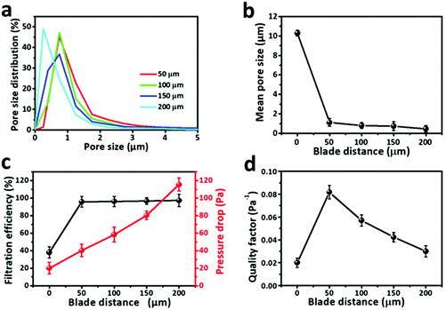
Due to the existence of ANFs, the SSA of ANF/melt-blown nonwovens with different blade distances was significantly larger than that of the uncoated nonwoven (Fig. S6†). At a blade distance of 50 μm, the SSA was 11.5 m2 g−1, whereas a further increase of blade distance to 200 μm would not lead to an obvious increase of SSA. The pore size of the ANF/melt-blown nonwoven composites was significantly smaller than that of the uncoated nonwoven. As can be seen in Fig. 5a, b and Fig. S5,† the pore size of the melt-blown nonwoven ranged from 5 to 17 μm, and the average pore size was ∼10 μm. When coated at a blade distance of 50 μm, the average pore size experienced a sharp decrease to ∼1.2 μm. The pore size distribution became narrower after coating, reflecting that ANFs were uniformly distributed on the nonwoven surface. Increasing the blade distance would result in a denser structure with a smaller pore size. When the blade distance reached 200 μm, the average pore size was less than 0.7 μm.
The filtration performances of ANF/melt-blown nonwoven composites were then evaluated using charge neutralized NaCl aerosol particles with a continuous airflow of 32 L min−1. Fig. 5c shows the effects of ANFs on the filtration efficiency and pressure drop of the composite filter. Before coating, the melt-blown nonwoven showed a low filtration efficiency of 38.8%, and the pressure drop was 22.3 Pa. With the existence of ANFs, the filtration efficiencies have been significantly improved. The increase of blade distance from 50 to 200 μm showed slight impacts on the filtration efficiency (from 95.3% to 96.7%). However, due to the increased number of ANFs, more obstacles were formed for air to pass through the sample, which caused an almost linear increase of pressure drop. As shown in Fig. 5d, the highest QF (0.082 Pa−1) was reached at a blade distance of 50 μm, demonstrating that filtration performances could be significantly improved by ANF films with an appropriate density.
Since the air flow rate is often dynamic in actual use, we studied the effect of air flow rates on filtration performances. In general, the filtration efficiencies of both ANF/melt-blown and pristine melt-blown nonwovens were negatively correlated with air flow, whereas the pressure drop was positively correlated with air flow (Fig. S7†). It is noteworthy that the filtration efficiency of the ANF/melt-blown composite remained at a high level (92.28%) under the maximum air flow of 100 L min−1, which clearly suggested the feasibility of using this filter in various filtration applications.
Besides filtration performances, the combination of the ANF film with the melt-blown nonwoven also led to a notable improvement in breaking strength. Owing to the high rigidity and the inter-connected network of ANFs, a thin layer of the ANF film made the stress of the composite nonwoven increase by at least 25% (Fig. 6a). Although the strain inevitably dropped from 29% to 26% after coating, the actual application of the nonwoven composite would not be interfered by such a small decrease of strain. For samples coated at different blade distances, a denser ANF film would result in a larger strength and a smaller flexibility. The bulky structure and the abundant nano- and submicron pores of the ANF/melt-blown nonwoven composite could effectively limit heat conduction in the solid state and heat convection in the gaseous state. According to Fig. 6b, the thermal conductivities of ANF/melt-blown nonwovens were 0.0234–0.0264 W (m K)−1, which were much lower than that of the uncoated melt-blown nonwoven (0.0451 W (m K)−1). The thermal stability was also greatly improved in the presence of ANFs, as the initial decomposition temperature of the composite was higher than that of the pure melt-blown nonwoven (Fig. 6c). More importantly, the high rigidity and thermal stability of ANFs work synergistically to prevent the thermal shrinkage of the composite nonwoven. Both the MD and CD of the coated nonwovens could retain their original dimensions at elevated temperatures, whereas the shrinkage of the pure melt-blown nonwoven started at 160 °C and became more severe at 170 °C (Fig. 6d). The enhancements in mechanical and thermal properties make us believe that the ANF/melt-blown nonwovens, when used for filtration purposes, may show both desirable filtration performances and a broad application field.
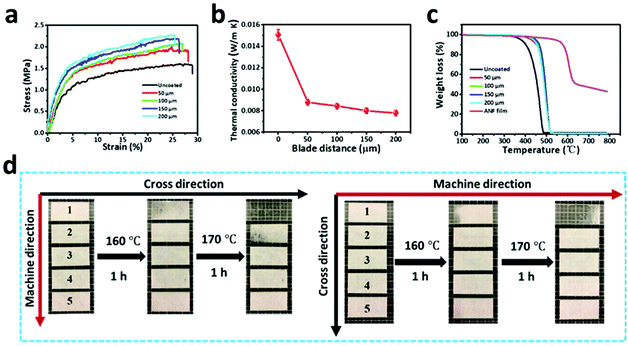 | ||
| Fig. 6 (a) Stress–strain curves, (b) thermal conductivities, (c) TGA, and thermal contraction behaviours of the pure melt-blown nonwoven and ANF/melt-blown nonwoven with different blade distances. | ||
4. Conclusions
In summary, an ANF-based coating method was developed to fabricate ANF/melt-blown nonwoven composites. At the preparation temperature of 60 °C, completely deprotonated ANFs could be acquired within 8 hours, which was much faster than the traditional method. The tiny but numerous pores from the ANF film greatly improved the filtration performances of the nonwoven composites. The mechanical properties and thermal stability were also enhanced due to the existence of ANFs, proving the efficacy of coating ANFs on conventional nonwovens as high performance air filters.Conflicts of interest
There are no conflicts to declare.Acknowledgements
The authors acknowledge the support from the National Natural Science Foundation of China (32071340), the Science and Technology Commission of Jiaxing Program (2021AY10063), and the Open Project Program of Key Laboratory of Yarn Materials Forming and Composite Processing Technology of Zhejiang Province (MTC-2020-08).References
- B. Yang, M. Zhang, Z. Lu, J. Luo, S. Song, J. Tan and Q. Zhang, Composites, Part B, 2018, 154, 166–174 CrossRef CAS.
- Q. Yin, H. Jia, A. Mohamed, Q. Ji and L. Hong, Nanoscale, 2020, 12, 5507–5520 RSC.
- M. A. Abtew, F. Boussu, P. Bruniaux, C. Loghin and I. Cristian, Appl. Sci., 2020, 10, 4873 CrossRef CAS.
- D. Ahmed, H. Zhong, H. Kong, J. Liu, Y. Ma and M. Yu, Mater. Res.-Ibero-A. M. -J., 2014, 17, 1180–1200 Search PubMed.
- S. Dewilde, T. Vander Hoogerstraete, W. Dehaen and K. Binnemans, ACS Sustain. Chem. Eng., 2018, 6, 1362–1369 CrossRef CAS.
- Y. Zhang, Y. Huang, L. Liu and L. Wu, J. Appl. Polym. Sci., 2007, 106, 2251–2262 CrossRef CAS.
- K. Tanaka, K. Minoshima, W. Grela and K. Komai, Compos. Sci. Technol., 2002, 62, 2169–2177 CrossRef CAS.
- W. Cao, L. Yang, X. Qi, Y. Hou, J. Zhu and M. Yang, Adv. Funct. Mater., 2017, 27, 1701061 CrossRef.
- F. Xie, F. Jia, L. Zhuo, Z. Lu, L. Si, J. Huang, M. Zhang and Q. Ma, Nanoscale, 2019, 11, 23382–23391 RSC.
- M. Yang, K. Cao, L. Sui, Y. Qi, J. Zhu, A. Waas, E. M. Arruda, J. Kieffer, M. D. Thouless and N. A. Kotov, ACS Nano, 2011, 5, 6945–6954 CrossRef CAS PubMed.
- P. Flouda, A. H. Quinn, A. G. Patel, D. Loufakis, D. C. Lagoudas and J. L. Lutkenhaus, Nanoscale, 2020, 12, 16840–16850 RSC.
- J. U. Lee, B. Park, B. S. Kim, D. R. Bae and W. Lee, Composites, Part A, 2016, 84, 482–489 CrossRef CAS.
- J. Zhu, W. X. Cao, M. Yue, Y. Hou, J. Han and M. Yang, ACS Nano, 2015, 9, 2489–2501 CrossRef CAS PubMed.
- M. Yang, K. Cao, B. Yeom, M. D. Thouless, A. Waas, E. M. Arruda and N. A. Kotov, J. Compos. Mater., 2015, 49, 1873–1879 CrossRef CAS.
- J. Fan, J. Wang, Z. Shi, S. Yu and J. Yin, Mater. Chem. Phys., 2013, 141, 861–868 CrossRef CAS.
- J. Fan, Z. Shi, L. Zhang, J. Wang and J. Yin, Nanoscale, 2012, 4, 7046–7055 RSC.
- B. Park, W. Lee, E. Lee, S. H. Min and B. S. Kim, ACS Appl. Mater. Interfaces, 2015, 7, 3329–3334 CrossRef CAS PubMed.
- S. O. Tung, S. L. Fisher, N. A. Kotov and L. T. Thompson, Nat. Commun., 2018, 9, 4193 CrossRef PubMed.
- J. Li, W. Tian, H. Yan, L. He and X. Tuo, J. Appl. Polym. Sci., 2016, 133, 43623 Search PubMed.
- S. O. Tung, S. Ho, M. Yang, R. Zhang and N. A. Kotov, Nat. Commun., 2015, 6, 6152 CrossRef CAS PubMed.
- Y. Yuan, J. Li, Y. Liu, T. Chen and J. Lin, Polym. Compos., 2018, 39, 2411–2419 CrossRef CAS.
- C. Nie, Y. Yang, Z. Peng, C. Cheng, L. Ma and C. Zhao, J. Membr. Sci., 2017, 528, 251–263 CrossRef CAS.
- Z. Peng, Y. Yang, J. Luo, C. Nie, L. Ma, C. Cheng and C. Zhao, Biomater. Sci., 2016, 4, 1392–1401 RSC.
- C. Nie, Z. Peng, Y. Yang, C. Cheng, L. Ma and C. Zhao, J. Hazard. Mater., 2016, 318, 255–265 CrossRef CAS PubMed.
- B. Yang, M. Zhang, Z. Lu, J. Luo, S. Song and Q. Zhang, ACS Sustainable Chem. Eng., 2018, 6, 8954–8963 CrossRef CAS.
- W. Tian, T. Qiu, Y. Shi, L. He and X. Tuo, Mater. Lett., 2017, 202, 158–161 CrossRef CAS.
- S. R. Kwon, J. Harris, T. Zhou, D. Loufakis, J. G. Boyd and J. L. Lutkenhaus, ACS Nano, 2017, 11, 6682–6690 CrossRef CAS PubMed.
- S. R. Kwon, M. B. Elinski, J. D. Batteas and J. L. Lutkenhaus, ACS Appl. Mater. Interfaces, 2017, 9, 17126–17136 Search PubMed.
- Y. Li, G. Ren, Z. Zhang, C. Teng, Y. Wu, X. Lu, Y. Zhu and L. Jiang, J. Mater. Chem. A, 2016, 4, 17324–17332 RSC.
- J. Lyu, X. Wang, L. Liu, Y. Kim, E. K. Tanyi, H. Chi, W. Feng, L. Xu, T. Li, M. A. Noginov, C. Uher, M. D. Hammig and N. A. Kotov, Adv. Funct. Mater., 2016, 26, 8435–8445 CrossRef CAS.
- H. Zhang, L. Feng, Y. Liang and T. Xu, Nanoscale, 2019, 11, 437–443 RSC.
- J.M. Koo, H. Kim, M. Lee, S. A. Park, H. Jeon, S. H. Shin, S. M. Kim, H. G. Cha, J. Jegal, B. S. Kim, B. G. Choi, S. Y. Hwang, D. X. Oh and J. Park, Macromolecules, 2019, 52, 923–934 CrossRef.
- B. Yang, L. Wang, M. Zhang, J. Luo and X. Ding, ACS Nano, 2019, 13, 7886–7897 CrossRef CAS PubMed.
- F. Zeng, X. Chen, G. Xiao, H. Li, S. Xia and J. Wang, ACS Nano, 2020, 14, 611–619 CrossRef CAS PubMed.
- K. Xu, Y. Qin, T. Xu, X. Xie, J. Deng, J. Qi and C. Huang, J. Membr. Sci., 2019, 592, 117364 CrossRef CAS.
- K. Xu, J. Deng, R. Lin, H. Zhang, Q. Ke and C. Huang, J. Mater. Chem. A, 2020, 8, 22269–22279 RSC.
- Y. Wang, Y. Xu, D. Wang, Y. Zhang, X. Zhang, J. Liu, Y. Zhao, C. Huang and X. Jin, ACS Appl. Mater. Interfaces, 2019, 11, 48437–48449 CrossRef CAS PubMed.
- M. Yang, K. Q. Cao, L. Sui, Y. Qi, J. Zhu, A. Waas, E. M. Arruda, J. Kieffer, M. D. Thouless and N. A. Kotov, ACS Nano, 2011, 5, 6945–6954 CrossRef CAS PubMed.
- R. R. Burch, W. Sweeny, H. W. Schmidt and Y. H. Kim, Macromolecules, 1990, 23, 1065–1072 CrossRef CAS.
- B. Yang, W. Li, M. Zhang, L. Wang and X. Ding, ACS Nano, 2021, 15, 7195–7207 CrossRef CAS PubMed.
- R. Edmunds and M. A. Wadee, Compos. Sci. Technol., 2005, 65, 1284–1298 CrossRef CAS.
- B. Yang, L. Wang, M. Zhang, J. Luo, Z. Lu and X. Ding, Adv. Funct. Mater., 2020, 30, 2000186 CrossRef CAS.
- P. Samyn, A. Barhoum, T. Öhlund and A. Dufresne, J. Mater. Sci., 2017, 53, 146–184 CrossRef.
- D. Li, X. Gou, D. Wu and Z. Guo, Nanoscale, 2018, 10, 6695–6703 RSC.
- M. Yang, Z. Zhang, J. Yuan, L. Wu, P. Li, X. Zhao and X. Men, Polym. Compos., 2020, 41, 4192–4201 CrossRef CAS.
- X. Zhang, J. Liu, H. Zhang, J. Hou, Y. Wang, C. Deng, C. Huang and X. Jin, Polymers, 2021, 13, 485 CrossRef CAS PubMed.
- J. Liu, H. Zhang, H. Gong, X. Zhang, Y. Wang and X. Jin, ACS Appl. Mater. Interfaces, 2019, 11, 40592–40601 CrossRef CAS PubMed.
- C. Liu, Z. Dai, B. He and Q. Ke, Materials, 2020, 13, 4774 CrossRef CAS PubMed.
- Z. Dai, J. Su, X. Zhu, K. Xu, J. Zhu, C. Huang and Q. Ke, J. Mater. Chem. A, 2018, 6, 14856–14866 RSC.
- X. Chen, Y. Xu, M. Liang, Q. Ke, Y. Fang, H. Xu, X. Jin and C. Huang, J. Hazard. Mater., 2018, 347, 325–333 CrossRef CAS PubMed.
Footnotes |
| † Electronic supplementary information (ESI) available: Photographs of colour changes during solution preparation; the UV/VIS spectra of ANF dispersions at different times; the pore size distribution of the pure melt-blown nonwoven. See DOI: 10.1039/d1nr06159c |
| ‡ These two authors are co first authors, and their contributions to this article are the same. |
| This journal is © The Royal Society of Chemistry 2022 |


