 Open Access Article
Microwave-assisted in situ ring-opening polymerization of ε-caprolactone in the presence of modified halloysite nanotubes loaded with stannous chloride†
Gang Yang ,
Rui Ma
 *,
Shifan Zhang,
Ziying Liu,
Dexuan Pei,
Hongyun Jin
 *,
Jiaqi Liu and
Wenjie Du
Faculty of Materials Science and Chemistry, China University of Geosciences, Wuhan 430074, China. E-mail: ruima@cug.edu.cn; jinhongyun@cug.edu.cn
First published on 10th January 2022
Abstract
Polycaprolactone (PCL) has been widely applied for its excellent physicochemical properties, but it also has common problems with biopolymers. It is important to investigate energy-efficient polymerization crafts and composite catalytic systems in the ring-opening polymerization (ROP) of ε-caprolactone (ε-CL) to prepare high-performance PCL matrix composites. In this study, a composite catalytic system of modified halloysite nanotubes loaded with stannous chloride (APTES-P-h-HNTs-SnCl2) was successfully synthesized via hydroxylation, calcination, silane coupling agent modification and physical loading. It was used to catalyze the microwave-assisted in situ ROP of ε-CL to synthesize PCL matrix nanocomposites with modified halloysite nanotubes (PCL-HNTs). The structure, morphology, polymerization, thermal properties and electrochemical performance of products were subsequently investigated. The results show that PCL-HNTs have been successfully synthesized with connected petal-like and porous structures. Compared with PCL, the film-forming and thermal properties of PCL-HNTs have been significantly improved. Moreover, PCL-HNTs have a potential application value in the field of solid polymer electrolytes (SPEs).
1. Introduction
As one of the most important biodegradable polymer materials, polycaprolactone (PCL) is widely used in the field of tissue engineering,1 biomaterials and packaging system for its excellent physicochemical properties of biocompatibility, biodegradability, processability, sharp memory function, low toxicity and drug permeability.2–4PCL is commonly synthesized by the ring-opening polymerization (ROP) of ε-caprolactone (ε-CL) in bulk or organic solvents. On the one hand, the ROP mechanisms of ε-CL can be roughly divided into five categories, i.e., anionic polymerization, cationic polymerization, organocatalytic polymerization, enzymatic polymerization, and coordination-insertion polymerization.5 Among them, the coordination-insertion polymerization is well studied because it can produce PCL with a clear structure and controllable molecular weights.6 On the other hand, there are a wide variety of systems used to catalyse the ROP of ε-CL. Currently, the most commonly used catalyst systems mainly contain four types, i.e., metal-based compounds, enzymatic compounds, organic compounds and inorganic acids.7
Although PCL has remarkable properties as mentioned above, there are still some problems. The ROP of ε-CL is traditionally carried out by conventional heating, generally taking more than 24 h to complete.8 It has high energy costs and is inefficient. Besides, similar to most biopolymers, the thermal properties and mechanical properties of PCL are not excellent enough, which limit the applications of PCL in high-temperature processing or high-strength devices. Even if PCL has potential in the field of solid polymer electrolytes (SPEs) of lithium-ion batteries,9–11 it is semi-crystalline, which obstructs the transport of lithium ions in PCL-based SPE and leads to low ion conductivity.12 Therefore, the use of energy efficient ε-CL polymerization crafts and improvements in the comprehensive performance of PCL are of important value.
Microwave-assisted heating is totally different from conventional heating. Microwave irradiation has been proved to dramatically accelerate the polymerization of monomers, which contain polar groups that absorb microwaves.13 Over the last decades, microwave irradiation has developed into a highly useful technique and an effective alternative energy source for chemical reactions and processes.14 Compared with conventional heating ring-opening polymerization (HROP), microwave-assisted ring-opening polymerization (MROP) has many advantages, including rate enhancement, environmentally friendly, safety, high-temperature homogeneity and manufacture of high-value low-volume chemicals.15 Thus, MROP is an environmental and high-efficiency technique for the synthesis of PCL.
In recent years, polymer matrix composites have been greatly developed by the integration of organic and inorganic fillers into polymers.16 Their various properties, such as ion conductivity, mechanical properties and thermal stability,17–19 have improved significantly compared with pure polymers. In this way, high-performance PCL matrix composites can be produced. Halloysite is a kind of natural layered silicate mineral, containing rich silicon and aluminate active sites. It is chemically similar to kaolinite and have a chemical formula of Al2(OH)4Si2O5·(0–2)H2O.20 Halloysite nanotubes (HNTs) are the dominant form of natural halloysite, with a multi-layered tubular structure.21 The global supply of HNTs exceeds thousands of tons per year and HNTs are low-cost, meaning that mass-scale industrial applications can be achieved.22 HNTs are a kind of promising filler for high-performance polymer matrix composites,23 due to their high specific surface area (SSA), high aspect ratio, good dispersion, nontoxicity, high strength, and excellent thermal stability.24 Furthermore, HNTs are widely used in the catalysis industry, as additives in catalytic systems or promising materials for the preparation of heterogeneous catalysts, etc.25–29 As far as HNTs are concerned, the abundant hydroxyl groups on the internal lumen surface and aluminate active sites have the synergetic catalytic ability in the case of ROP of ε-CL.30 However, if only catalyzed by HNTs, the chain growth of the polymerization results in short chains, which is manifested by the low molecular weight and poor performance of corresponding PCL products. A better option is to use HNTs as the support of catalysts. Due to the tubular structure, high SSA and active sites, HNTs are of great application value as a host for the loading of various guests.31–33 By loading certain catalysts on modified HNTs through physical forces or chemical reactions, a composite catalytic system with excellent catalytic performance can be constructed. In the polymerization catalyzed by the composite catalytic system, the chain growth starts at the active sites on the surface of HNTs, and in situ polymerization occurs. Compared with physically blending fillers with polymers, fillers can be better dispersed in the polymer matrix by in situ polymerization, and the interactions are stronger among the polymer, surfactant and filler surface.34 Correspondingly, PCL-HNTs synthesized by the composite catalytic system have better performance and higher molecular weight than the PCL matrix nanocomposites catalyzed by only HNTs or physically blending with inorganic fillers.
In this work, a composite catalytic system, modified halloysite nanotubes loaded with stannous chloride (APTES-P-h-HNTs-SnCl2), was creatively synthesized. It not only has excellent catalytic ability but also acts as the performance-enhancing filler of polymer matrix composites. The microwave-assisted in situ ROP of ε-CL in the presence of APTES-P-h-HNTs-SnCl2 was carried out to synthesize PCL-HNTs and their structures, thermal properties and electrochemical performances were significantly investigated.
2. Experimental
2.1. Materials
ε-Caprolactone (ε-CL, 99%), from Alladin, was distilled under vacuum and stored with a calcined molecular sieve. High-purity halloysite nanotubes (HNTs), from Yuanxin Nano Technology Co., Ltd (Guangzhou, China), were vacuum dried before use. Stannous chloride (SnCl2, 99%), from Mucklin, was used without further purification. (3-Aminopropyl)triethoxysilane (APTES, H2NCH2CH2CH2Si(OC2H5)3, ≥98%), from Lvwei New Material Technology Co., Ltd (Guangdong, China), was used without further purification. All other reagents were used as received.2.2. Preparation of APTES-P-h-HNTs-SnCl2
As shown in Scheme 1, 4.00 g of HNTs were dispersed in 200 mL deionized water. Subsequently, 0.116 g NaOH was added and the mixture was magnetically stirred for 24 h at room temperature.35 The solid phase of the resultant hydroxylated HNTs (h-HNTs) was obtained by centrifugal separation and rinsed several times with water until the pH of the filtrate reached 7. The prepared h-HNTs were first dried at 60 °C for 2 h in an oven and then dried at 60 °C in a vacuum oven for 24 h.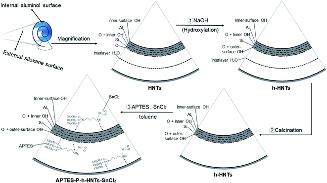 | ||
| Scheme 1 Schematic illustration of structures and preparation processes from HNTs to APTES-P-h-HNTs-SnCl2. | ||
The h-HNTs obtained were calcined at 400 °C for 3 h to remove the interlayer water of HNTs.36 Then, calcined h-HNTs were ground into powder using a quartz mortar. To physically load SnCl2 onto the surface of h-HNTs, SnCl2 (2.10 mmol), toluene (45 mL) and h-HNTs (3.33 g) were added to a 150 mL reaction flask with a branch nozzle. The APTES (2.55 mmol) and toluene (25 mL) were also added to a 50 mL beaker and well mixed.37 The ligand solution in the beaker was then added to the reaction flask and three nitrogen purge cycles were applied to the reaction flask. Finally, the solution system was stirred overnight to obtain the composite catalytic system of APTES-P-h-HNTs-SnCl2.
2.3. Microwave-assisted in situ ROP
Microwave-assisted polymerizations were carried out in an MCR-3 atmospheric-pressure microwave chemical reactor. The typical procedure was as follows. A mixture of ε-CL and corresponding certain proportions of APTES-P-h-HNTs-SnCl2 or SnCl2 (as the control groups) were ultrasonically mixed and then placed into a three-necked reaction flask. Through three times of vacuum–nitrogen cycles, the mixture was irradiated and then polymerized at certain constant temperatures stabilized by the reaction microwave power of 400 W. The crude solid product was dissolved in methylene chloride and precipitated using methanol. The precipitate was filtered and dried under a vacuum at 40 °C.In the following content, PCL-HNTs and PCL, respectively, represented products from ε-CL catalyzed by APTES-P-h-HNTs-SnCl2 and SnCl2. Moreover, PCL-HNTs (1 wt%) and PCL-HNTs (3 wt%), respectively, represented PCL-HNTs [initiator/monomer (I/M) mass ratio = 1%] and PCL-HNTs (I/M mass ratio = 3%).
2.4. Fabrication of composite polymer electrolytes
Composite polymer electrolytes (CPEs) were prepared by a solution casting method.38 Appropriate amounts of PCL-HNTs and LITFSI to give [O]![[thin space (1/6-em)]](https://www.rsc.org/images/entities/char_2009.gif) :
:![[thin space (1/6-em)]](https://www.rsc.org/images/entities/char_2009.gif) [Li] ratio of 20
[Li] ratio of 20![[thin space (1/6-em)]](https://www.rsc.org/images/entities/char_2009.gif) :
:![[thin space (1/6-em)]](https://www.rsc.org/images/entities/char_2009.gif) 1 were dissolved in dimethyl carbonate, and the solution was stirred at 55 °C for 2 h. A predetermined amount of Al2O3 powder with different particle size was then added, and the solution was mixed for 24 h with continuous heating. When complete homogenization of a mixture occurred, the solution was cast on a glass plate using a doctor blade. Residual solvent was completely removed by drying the electrolyte film at room temperature for another 24 h. Then, the obtained CPEs membranes were cut into circular rounds with a diameter of 19 mm and placed in an Ar-filled glove box overnight to remove the residual solvent and finally for electrochemical tests.
1 were dissolved in dimethyl carbonate, and the solution was stirred at 55 °C for 2 h. A predetermined amount of Al2O3 powder with different particle size was then added, and the solution was mixed for 24 h with continuous heating. When complete homogenization of a mixture occurred, the solution was cast on a glass plate using a doctor blade. Residual solvent was completely removed by drying the electrolyte film at room temperature for another 24 h. Then, the obtained CPEs membranes were cut into circular rounds with a diameter of 19 mm and placed in an Ar-filled glove box overnight to remove the residual solvent and finally for electrochemical tests.
2.5. Measurements
X-ray photoelectron spectroscopy (XPS) was performed on a ‘Thermo Scientific K-Alpha’ with an Al Kα source (1486.6 eV). The full-spectrum scan (pass energy: 160 eV) and the narrow-spectrum scan (pass energy: 50 eV) were conducted on all samples. All spectra were calibrated using the C 1s peak (284.80 eV).1H NMR spectra were recorded on a ‘Bruker 400M’ spectrometer using tetramethylsilane as an internal standard and CDCl3 as a solvent.
X-ray diffraction (XRD) patterns were performed on a ‘Bruker D8 Advance’ with Cu Kα radiation, in the 2θ rotation range of −110° to 168°.
Hitachi SU8010 high-resolution field emission scanning electron microscope (SEM) was applied to investigate the surface morphology and cross-sectional structure of HNTs, APTES-P-h-HNTs-SnCl2, PCL and PCL-HNTs.
The number-average molecular weight (Mn) and polymer dispersity index (PDI) of PCL-HNTs were determined using gel permeation chromatography (GPC) of a ‘Breeze 2 Hplc 1525’ instrument. N,N-Dimethylformamide was used as an eluent at a flow rate of 1.0 mL min−1 and GPC data were calibrated by standard polymethyl methacrylate.
Differential scanning calorimetry (DSC) was performed using a ‘Netzsch DSC 204 F1’ and the test process was set as followed. Firstly, at a heating rate of 20 °C min−1, samples were heated from ambient temperature to 80 °C, and kept isothermally at 80 °C for 10 minutes. Secondly, at a temperature ramp rate of 50 °C min−1, samples were cooled from 80 °C to −80 °C, and maintained under isothermal temperature for 10 minutes. Finally, samples were heated from −80 °C to 80 °C at a heating rate of 20 °C min−1.
Thermal stabilities were performed using a ‘Netzsch STA 2500’. The sample was heated from 30 °C to 630 °C in a nitrogen atmosphere at a heating rate of 10 °C min−1, without heat preservation.
AC impedance and ionic conductivity measurements on CPEs were performed using a ‘Zennium X’ Zahner electrochemical workstation over the frequency range of 10 MHz to 100 mHz. CPE films were sandwiched between two stainless steel disk electrodes and measured from 30 °C to 60 °C. The charge/discharge tests were performed using a ‘CT2001A’ from the LAND system.
3. Results and discussion
3.1. Effect of modification treatments on HNTs
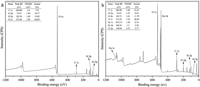
XPS survey scans of HNTs and APTES-P-h-HNTs-SnCl2 are shown in Fig. 1. Characteristic elements including aluminium, carbon, chlorine, sodium, oxygen, silicon and tin were detected.Sodium was only detected in APTES-P-h-HNTs-SnCl2, confirming the effectiveness of the hydroxylation treatment. The relative concentrations of aluminium to oxygen and silicon to oxygen both decreased from HNTs to APTES-P-h-HNTs-SnCl2. This can be ascribed to the alkaline etching of aluminium oxide octahedral layers and silicon oxide tetrahedron layers of HNTs. Since the inner and outer surfaces of HNTs were reactive during the hydroxylation treatment, parts of aluminium and silicon were dissolved in the form of AlO2− and SiO32− (aq.), and extra aluminium hydroxyl groups and silanol groups were generated.
Tin and chlorine were only detected in APTES-P-h-HNTs-SnCl2, confirming the effectiveness of the silane coupling agent treatment and physical loading of stannous chloride. The atomic percentages of tin and chlorine were 5.38% and 3.77%. This is because the HNTs were physically absorbed with APTES acting simultaneously as a support and a ligand of stannous chloride. The stannous chloride catalyst was physically adsorbed onto the surface of HNTs.
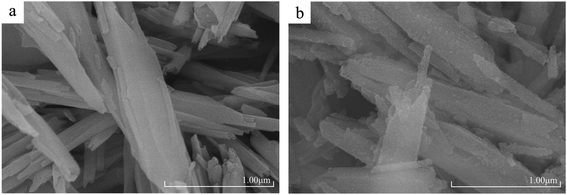
Fig. 2(a) exhibited the microscopic morphology of HNTs, including high aspect ratios, smooth surfaces and tubular structures. This also reflected the high purity of HNTs used in this work. Otherwise, the morphology of APTES-P-h-HNTs-SnCl2 could be seen in Fig. 2(b), showing a clear difference from HNTs. After hydroxylation, calcination, silane coupling agent modification and stannous chloride physical adsorption, the halloysite nanotubes still had a high aspect ratio, but the tubular structure was damaged and there were obvious particles on the surface with attachments. SEM micrographs more intuitively proved the success of the above modifications of HNTs.
3.2. PCL-HNTs characterization
Hard and lumpy products were obtained when ε-CL was irradiated using microwaves in the presence of APTES-P-h-HNTs-SnCl2. As shown in Table 1, the Mn values of the products ranged from 9700 to 53![[thin space (1/6-em)]](https://www.rsc.org/images/entities/char_2009.gif) 000 g mol−1 with a polymer dispersity index (Mw/Mn) of 1.11–1.61.
000 g mol−1 with a polymer dispersity index (Mw/Mn) of 1.11–1.61.
| n | I/M (wt%) | T (°C) | t (min) | CR (%) | Mn (g mol−1) | PDI |
|---|---|---|---|---|---|---|
| 1 | 1 | 210 | 30 | 80.1 | 19![[thin space (1/6-em)]](https://www.rsc.org/images/entities/char_2009.gif) 497 497 |
1.29 |
| 2 | 1 | 210 | 40 | 81.4 | 20![[thin space (1/6-em)]](https://www.rsc.org/images/entities/char_2009.gif) 426 426 |
1.56 |
| 3 | 1 | 210 | 60 | 82.5 | 21![[thin space (1/6-em)]](https://www.rsc.org/images/entities/char_2009.gif) 997 997 |
1.39 |
| 4 | 1 | 250 | 5 | 36.3 | 14![[thin space (1/6-em)]](https://www.rsc.org/images/entities/char_2009.gif) 134 134 |
1.11 |
| 5 | 1 | 250 | 10 | 79.3 | 23![[thin space (1/6-em)]](https://www.rsc.org/images/entities/char_2009.gif) 913 913 |
1.40 |
| 6 | 1 | 250 | 20 | 88.8 | 29![[thin space (1/6-em)]](https://www.rsc.org/images/entities/char_2009.gif) 711 711 |
1.56 |
| 7 | 1 | 250 | 30 | 93.2 | 36![[thin space (1/6-em)]](https://www.rsc.org/images/entities/char_2009.gif) 482 482 |
1.56 |
| 8 | 1 | 250 | 40 | 94.8 | 48![[thin space (1/6-em)]](https://www.rsc.org/images/entities/char_2009.gif) 161 161 |
1.52 |
| 9 | 1 | 250 | 60 | 93.9 | 52![[thin space (1/6-em)]](https://www.rsc.org/images/entities/char_2009.gif) 088 088 |
1.48 |
| 10 | 3 | 250 | 5 | 25.2 | 9785 | 1.11 |
| 11 | 3 | 250 | 10 | 71.0 | 21![[thin space (1/6-em)]](https://www.rsc.org/images/entities/char_2009.gif) 253 253 |
1.12 |
| 12 | 3 | 250 | 20 | 86.9 | 24![[thin space (1/6-em)]](https://www.rsc.org/images/entities/char_2009.gif) 472 472 |
1.61 |
| 13 | 3 | 250 | 30 | 93.9 | 30![[thin space (1/6-em)]](https://www.rsc.org/images/entities/char_2009.gif) 031 031 |
1.57 |
| 14 | 3 | 250 | 40 | 92.3 | 31![[thin space (1/6-em)]](https://www.rsc.org/images/entities/char_2009.gif) 777 777 |
1.51 |
| 15 | 3 | 250 | 60 | 94.8 | 32![[thin space (1/6-em)]](https://www.rsc.org/images/entities/char_2009.gif) 494 494 |
1.52 |
The influence factors of polymerization, including polymerization temperatures stabilized by MCR-3 with certain microwave power, I/M mass ratios and the time of microwave irradiation, were investigated. In this work, the reaction microwave power was 400 W, polymerization temperatures were set to 210 °C and 250 °C, initiator/monomer (I/M) mass ratios were respectively 1% and 3%, and the irradiation time was from 5 to 60 min. Among them, the best conditions for the microwave-assisted in situ ROP of ε-CL were obtained, carrying out polymerizations at 250 °C, when the I/M mass ratio is 1%.
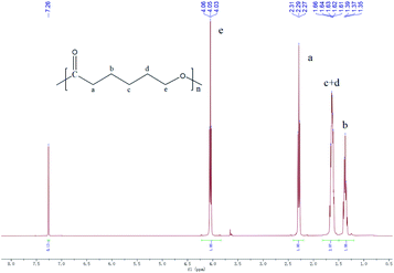
1H NMR analyses revealed the expected structures of the synthesized products under the experimental conditions. 1H NMR (400 MHz, chloroform-d, δ): 7.26 (s, 2H; Ar H), 4.05 (t, J = 6.7 Hz, 2H; OCH2), 2.29 (t, J = 7.5 Hz, 2H; CH2CO), 1.82–1.50 (m, 4H; CH2), 1.38 (d, J = 7.2 Hz, 2H; CH2) (Fig. 3). The 1H NMR spectrum of the synthesized products was the same as the authoritative sample of PCL.39
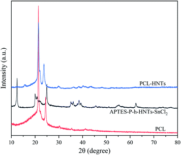
APTES-P-h-HNTs-SnCl2, PCL and PCL-HNTs were characterized using XRD, as shown in Fig. 4. The XRD pattern of PCL-HNTs was compared with those of PCL and HNTs to identify the characteristic peaks. PCL and HNTs exhibited characteristic peaks, showing semi-crystalline and crystalline nature, respectively.40 The appearance of all peaks in PCL-HNTs confirmed the presence of the two constituents.
The above results indicated that PCL-HNTs were successfully synthesized when the ROP of ε-CL was irradiated using microwaves and APTES-P-h-HNTs-SnCl2 as catalysts. As shown in Scheme 1 and Table 2, it could be inferred from the synthetic path of the composite catalytic system that there were three modes of the polymer molecular chain growth. In a first way, chain initiation occurred on the hydroxyl groups on the surface of the modified halloysite nanotubes, and the active hydrogen in the hydroxyl group attacked the C–O bond in caprolactone for the chain growth, resulting in PCL grafting on HNTs.30,41 The acidic nature of HNTs was the source of the polymerization behaviour. The ROP mechanism was cationic polymerization. The second was that hydroxyl groups on the surface of the modified HNTs reacted with SnCl2 to form alkoxy-tin, and then alkoxy-tin was coordinated with ε-CL to achieve the ROP of ε-CL, and the PCL grafted on HNTs was generated.42 The mechanism of ROP was coordination-insertion polymerization. The third was that chain initiation occurred on the stannous chloride physically loaded on the surface of the modified halloysite. The tin in the stannous chloride was coordinated with ε-CL, carrying out ROP of ε-CL and generating free PCL. The ROP mechanism was coordination-insertion polymerization.
| Sample | Free PCL rate (%) | Grafting rate (%) |
|---|---|---|
| PCL-HNTs(1 wt%)-10 min | 83.3 | 16.7 |
| PCL-HNTs(1 wt%)-20 min | 80.1 | 19.9 |
| PCL-HNTs(1 wt%)-30 min | 76.5 | 23.5 |
| PCL-HNTs(1 wt%)-40 min | 78.2 | 21.8 |
| PCL-HNTs(1 wt%)-60 min | 72.1 | 27.9 |
Among the three polymer chain growth modes, the last was the main one, because free PCL accounts for about three quarters in PCL-HNTs(1 wt%). The specific calculation method was to dissolve appropriate amounts of PCL-HNTs(1 wt%) in dichloromethane and centrifuge them at 10000 rpm. The solid component obtained by centrifugation was dissolved in dichloromethane and centrifuged at 10000 rpm again. The finally obtained solid component was APTES-P-h-HNTs-SnCl2 and its proportion of the mass of the APTES-P-h-HNTs-SnCl2 originally used corresponded to the proportion of the free PCL.
We reasoned that there existed a synergistic catalytic effect between the hydroxyl groups and the metal center, different from the catalytic action in simple metal-catalyzed reactions or organic catalytic reactions. All chain growth mechanisms simultaneously proceeded between the layers or on the surface of HNTs, conducting in situ ROP of ε-CL.
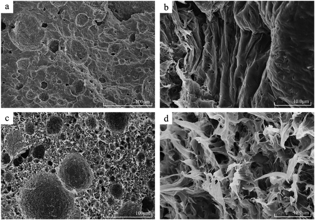
PCL and PCL-HNTs were subjected to liquid nitrogen brittle cooling and fracture operations to prepare samples. A high-resolution field emission scanning electron microscope was used to observe the cross-section of the sample and SEM micrographs of the synthesized PCL, PCL-HNTs(1 wt%) are exhibited in Fig. 5. The SEM micrograph of PCL shown in Fig. 5(a) indicated an obvious layer-packed structure, with some small pits. The local longitudinal morphology of high magnification was shown in Fig. 5(b), which showed that the distribution directions of the slice layers were consistent.
Fig. 5(c) is the SEM micrograph of PCL-HNTs(1 wt%) and totally different morphologies from PCL were observed. Catalyzed by APTES-P-h-HNTs-SnCl2, the microscopic morphology of PCL-HNTs(1 wt%) was no longer a lamellar structure, but a petal-like structure instead. Moreover, a porous structure appeared and distributed uniformly, and the average diameter of pits was slightly increased. The high-magnification local morphology of Fig. 5(d) clearly showed the petal-like structure of PCL-HNTs(1 wt%). The petals were even intertwined and interlaced, leaving many pores among them. The huge difference in the microscopic morphology of PCL-HNTs(1 wt%) and PCL could be explained by the fact that the chain initiation and chain growth of PCL-HNTs(1 wt%) were carried out on the active sites of the modified HNTs, macroscopically growing around HNTs due to the template effect. However, the polymerization for PCL was just a conventional chain proliferation catalyzed by SnCl2.
Structural differences between PCL and PCL-HNTs were apparent in their respective properties. The layered structure of PCL meant that it was prone to deformation and fracture when it was stressed. The absence of a porous structure also led to a stress concentration. Overall, the mechanical properties of PCL were brittle and soft. However, for PCL-HNTs, the petal-shaped three-dimensional connection structure guaranteed their mechanical strength, and HNTs themselves were also excellent polymer-reinforcing fillers, which helped to improve the mechanical properties of polymer nanocomposites. Meanwhile, the porous structure could disperse stress and enhance the toughness of PCL-HNTs. Overall, the mechanical properties of PCL-HNTs were tough and hard. In this work, the film-forming properties of PCL and PCL-HNTs verified their respective mechanical properties, and the film-forming properties of the latter were far superior to the former.
3.3. Thermal properties
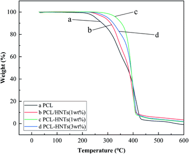
Thermal stabilities and thermal characterizations of PCL and PCL matrix nanocomposites with HNTs were respectively determined by thermogravimetry and differential scanning calorimetry.For thermal stabilities of polymer/filler nanocomposites could be affected by the polymer matrix, the filler and the interaction between the polymer matrix and the filler.43 In order to study these factors, targeted experiments were carried out, and the results were shown in Fig. 6. Sample b was the composite of PCL and HNTs prepared by physical blending.
As shown in Table 3, for the polymer matrix, the thermal performance of PCL was not excellent enough, the decomposition temperatures for the loss of 1 wt% and 5 wt% were 214.6 °C and 252.1 °C, respectively. For fillers, no matter how HNTs participate in the polymerization of ε-CL, the initial decomposition temperature of PCL matrix nanocomposites with HNTs was 31.4–81.2 °C, higher than PCL. The dispersion of fillers into the polymer matrix could help improve thermal stabilities because fillers could act as a superior insulator and mass transport barrier to the volatile products generated during decomposition.44 For the interaction between the polymer matrix and filler, the compatibility and dispersibility of the filler in the polymer matrix played a decisive role. For samples b and sample c, the mass ratios of HNTs to PCL were both 1%. In sample b, HNTs were physically mixed into the PCL matrix. However, in sample c, HNTs were first modified by APTES to increase their compatibility with polymers and then participated in the in situ ROP of ε-CL as the carrier and ligand of the composite catalytic system, which further improved the compatibility and dispersibility of HNTs in the PCL matrix. Therefore, comparing the above two samples, the initial decomposition temperature of sample c was about 45 °C higher than that of sample b.
| Sample | Td (1 wt% loss) | Td (5 wt% loss) |
|---|---|---|
| a – PCL | 214.6 °C | 252.1 °C |
| b – PCL/HNTs(1 wt%) | 246.0 °C | 287.5 °C |
| c – PCL-HNTs(1 wt%) | 291.6 °C | 333.3 °C |
| d – PCL-HNTs(3wt%) | 259.7 °C | 299.7 °C |
As proved from the thermal stability of four representative samples, APTES-P-h-HNTs-SnCl2 had good dispersibility and compatibility in the PCL matrix, and thermal stabilities of PCL-HNTs had been significantly improved, compared to that of PCL.
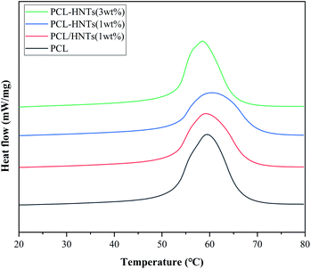
For thermal characterization of PCL and PCL matrix nanocomposites with HNTs, DSC thermograms of samples in the re-melting process were measured and are shown in Fig. 7. The melting temperature (Tm), the heat of fusion (ΔHm) and associated degree of crystallinity (χc) obtained from DSC measurements are summarized in Table 4. χc was calculated using the heat of fusion per gram of samples determined from the DSC measurements and heat of fusion corresponding to 100% crystalline PCL (136 J g−1).45 It is shown in Table 4 that the values of χc were reduced in the case of PCL matrix nanocomposites with HNTs as compared to PCL. This was due to the decrease in molecular mobility of PCL chains in nanocomposites that caused a reduction in the PCL crystal size and imperfections of the crystals.46 Similar behaviours were also observed for PCL/clay nanocomposites.47 In general, the crystallinity and melting point of the same material were positively correlated. Although the crystallinity of PCL matrix nanocomposites with HNTs was lower than the crystallinity of PCL, the melting point was maintained or even increased. This was because in PCL matrix nanocomposites with HNTs, intermolecular hydrogen bonds were formed between molecular chains and hydroxyls on the surface of modified HNTs and silane coupling agents.
| Sample | Tm (°C) | ΔHm (J g−1) | χc (%) |
|---|---|---|---|
| PCL | 52.4 | 58.42 | 43.0 |
| PCL/HNTs(1 wt%) | 52.4 | 48.82 | 35.9 |
| PCL-HNTs(1 wt%) | 53.0 | 42.54 | 31.3 |
| PCL-HNTs(3 wt%) | 52.9 | 47.08 | 34.6 |
3.4. Electrochemical performance of CPEs
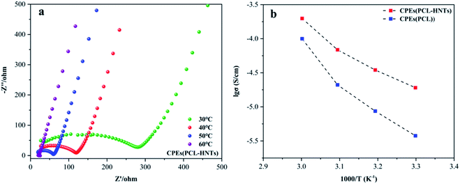
The polymer matrix of CPEs(PCL-HNTs) contained PCL-HNTs(1 wt%). The ionic conductivity (σ) values of electrolyte CPEs were determined using electrochemical impedance spectroscopy (EIS). Fig. 8(a) shows the Nyquist plot of the CPEs(PCL-HNTs) membrane. The semicircle at high frequency represented the impedance belonging to the electrolyte body. The σ of CPEs(PCL-HNTs) electrolyte was 1.91 × 10⁻⁵ S cm−1 at 30 °C, which was more than five times as much as that of the CPEs(PCL) electrolyte (3.77 × 10⁻⁶ S cm−1). The σ value increased with rising temperature, as shown in Fig. 8(b) and Table 5. Clearly, the σ of CPEs(PCL-HNTs) was always higher than that of CPEs(PCL) within the considered temperature range and finally reached up to 1.98 × 10⁻⁴ S cm−1 at 60 °C. This resulted from the lower χc of PCL-HNTs compared with PCL. During the transport of lithium ions in SPE, they coordinated with polar groups on the polymer chain at a specific position. Through the movement of the chain segment of polymer molecules, free volume appeared, so that lithium ions could be conducted within and between polymer molecular chains. In the polymer matrix, lower χc meant a greater proportion of amorphous regions, in which the segments could move at an ambient temperature higher than Tg. Therefore, lower χc of the polymer matrix caused higher σ of SPE.| Sample (S cm−1) | 30 °C | 40 °C | 50 °C | 60 °C |
|---|---|---|---|---|
| CPEs(PCL) | 3.77 × 10⁻⁶ | 8.65 × 10⁻⁶ | 2.10 × 10⁻⁵ | 9.98 × 10⁻⁵ |
| CPEs(PCL-HNTs) | 1.91 × 10⁻⁵ | 3.47 × 10⁻⁵ | 6.88 × 10⁻⁵ | 1.98 × 10⁻⁴ |
CPEs(PCL) were too brittle to be used in tests of lithium metal solid-state batteries. To evaluate the performance of the prepared CPEs(PCL-HNTs) in lithium metal solid-state batteries, LFP//CPE//Li batteries were assembled, and the discharge capacity was monitored at 60 °C. As shown in Fig. 9(a) and (b), the discharge capacity displays a rising trend with the increase in the cycle number, indicating a slowly activating process of the cell. Then, the reversible discharge capacity remained at the level of 163 mA h g−1 during the 20th to 50th cycles, showing good discharge capacity and electrochemical stability of CPEs(PCL-HNTs).
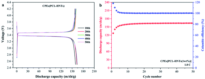 | ||
| Fig. 9 (a) Charge and discharge profiles, (b) cycle performance of CPEs(PCL-HNTs) in LiFePO4/CPEs/Li-battery. | ||
4. Conclusion
The composite catalytic system of APTES-P-h-HNTs-SnCl2 was prepared through hydroxylation, calcination, silane coupling agent modification and physical loading, and used as a catalyst for the microwave-assisted in situ ROP of ε-CL. Target products of PCL-HNTs were successfully synthesized and suitable polymerization conditions are microwave power of 400 W, I/M mass ratio of 1% and polymerization temperature of 250 °C. Compared with PCL, PCL-HNTs are observed to have connected petal-like and porous structures for the template effect of the catalyst and have much better film-forming and thermal stabilities. Moreover, lower χc of PCL-HNTs causes SPE made by PCL-HNTs to have higher lithium-ion conductivity. Meantime, CPEs(PCL-HNTs) have good discharge capacity and electrochemical stability, showing the application potentiality of PCL-HNTs in SPE. So, APTES-P-h-HNTs-SnCl2 is believed to not only act as a kind of an effective and efficient catalyst for the ROP of ε-CL but also effectively improve multiple properties of the PCL matrix, producing high-performance PCL-HNTs.Author contributions
Rui Ma and Hongyun Jin conceived the project. Gang Yang conducted the synthesis of materials and characterizations. Shifan Zhang helped pre-process some materials. Ziying Liu and Dexuan Pei conducted the electrochemical tests. Wenjie Du and Jiaqi Liu helped analyze the data. Gang Yang wrote the paper, Rui Ma and Hongyun Jin helped polish this manuscript. All the authors discussed the results and commented on the manuscript.Conflicts of interest
There are no conflicts to declare.Acknowledgements
This work was supported by grants from the National Natural Science Foundation of China (51903080), Natural Science Foundation of Hubei Province (2018CFC854), Scientific Research Foundation of Hubei University of Science and Technology (2019-20KZ06), the Open Project of Key Laboratory of Green Chemical Engineering Process of Ministry of Education (GCP20200210).References
- R. M. Mohamed and K. Yusoh, Adv. Mater. Res., 2016, 1134, 249–255 Search PubMed.
- J. M. Williams, A. Adewunmi, R. M. Schek, C. L. Flanagan, P. H. Krebsbach, S. E. Feinberg, S. J. Hollister and S. Das, Biomaterials, 2005, 26, 4817–4827 CrossRef CAS PubMed.
- F. Tay, D. Pashley, R. Loushine, S. Kuttler, F. Garcia-Godoy, N. King and M. Ferrari, American Journal of Dentistry, 2007, 20, 365 Search PubMed.
- Q. Meng, J. Hu, Z. Yong, L. Jing and L. Yan, J. Appl. Polym. Sci., 2007, 106, 2515–2523 CrossRef CAS.
- P. Lecomte and C. Jérôme, Synthetic biodegradable polymers, 2011, pp. 173–217 Search PubMed.
- P. Lecomte and R. Jérme, Ring Opening Polymerization, in Encyclopedia of Polymer Science and Technology, 2004 Search PubMed.
- M. Labet and W. Thielemans, Chem. Soc. Rev., 2009, 38, 3484–3504 RSC.
- X. M. Deng, M. L. Yuan, C. D. Xiong and X. H. Li, J. Appl. Polym. Sci., 2015, 71, 1941–1948 CrossRef.
- D. Zhang, L. Zhang, K. Yang, H. Wang, C. Yu, D. Xu, B. Xu and L.-M. Wang, ACS Appl. Mater. Interfaces, 2017, 9, 36886–36896 CrossRef CAS PubMed.
- T. Eriksson, J. Mindemark, M. Yue and D. Brandell, Electrochim. Acta, 2019, 300, 489–496 CrossRef CAS.
- Y. Seo, Y.-C. Jung, M.-S. Park and D.-W. Kim, J. Membr. Sci., 2020, 603, 117995 CrossRef CAS.
- Q. Zhou, J. Ma, S. Dong, X. Li and G. Cui, Adv. Mater., 2019, 31, 1902029 CrossRef CAS PubMed.
- D. M. Mingos and D. R. Baghurst, ChemInform, 2010, 22, 301 CrossRef.
- D. Adam, Nature, 2003, 421, 571–572 CrossRef CAS PubMed.
- C. R. Strauss, Microwaves in organic synthesis, 2002, pp. 35–60 Search PubMed.
- S. Ramakrishna, J. Mayer, E. Wintermantel and K. W. Leong, Compos. Sci. Technol., 2001, 61, 1189–1224 CrossRef CAS.
- E. Quartarone, P. Mustarelli and A. Magistris, Solid State Ionics, 1998, 110, 1–14 CrossRef CAS.
- Y. Xiang, Z. Peng and D. Chen, Eur. Polym. J., 2006, 42, 2125–2132 CrossRef CAS.
- Y. Tomita, T. Nakamura and A. Tago, Opt. Lett., 2008, 33, 1750–1752 CrossRef CAS PubMed.
- S. Balbir and I. D. R. Mackinnon, Clays Clay Miner., 1996, 44, 825–834 CrossRef.
- P. Yuan, P. D. Southon, Z. Liu, M. Green and J. Antill, J. Phys. Chem. C, 2008, 112, 15742–15751 CrossRef CAS.
- Y. M. Lvov, D. G. Shchukin, H. Mohwald and R. R. Price, ACS Nano, 2008, 2, 814–820 CrossRef CAS PubMed.
- M. Liu, Z. Jia, D. Jia and C. Zhou, Prog. Polym. Sci., 2014, 39, 1498–1525 CrossRef CAS.
- P. Yuan, D. Tan and F. Annabi-Bergaya, Appl. Clay Sci., 2015, 112–113, 75–93 CrossRef CAS.
- K. Ariga, H. Abe, Q. Ji and Y. M. Lvov, in Functional polymer composites with nanoclays, 2016, pp. 207–222 Search PubMed.
- J. Ouyang, Z. Zhao, H. Yang, Y. Zhang and A. Tang, Appl. Clay Sci., 2018, 152, 221–229 CrossRef CAS.
- S. Sadjadi, Appl. Clay Sci., 2020, 189, 105537 CrossRef CAS.
- Z. Li, L. Liu, A. J. González and D.-Y. Wang, Polym. Chem., 2017, 8, 3926–3936 RSC.
- P. Kumar, P. Gupta and C. Sharma, Catal. Sci. Technol., 2021, 11, 3775–3786 RSC.
- R. Ma, P. Hu, J. Fan, W. Tang, T. Chen and L. Shi, Polym.-Plast. Technol. Eng., 2018, 1–13 Search PubMed.
- B. P. G. R. R. Price and Y. Lvov, J. Microencapsulation, 2001, 18, 713–722 CrossRef PubMed.
- E. Abdullayev and Y. Lvov, J. Nanosci. Nanotechnol., 2011, 11, 10007–10026 CrossRef CAS PubMed.
- E. Abdullayev, K. Sakakibara, K. Okamoto, W. Wei, K. Ariga and Y. Lvov, ACS Appl. Mater. Interfaces, 2011, 3, 4040–4046 CrossRef CAS PubMed.
- C. Zeng and L. J. Lee, Macromolecules, 2001, 34, 4098–4103 CrossRef CAS.
- S. Zeng, C. Reyes, J. Liu, P. A. Rodgers and L. Sun, Polymer, 2014, 55, 6519–6528 CrossRef CAS.
- G. Brindley and J. Goodyear, Mineral. Mag. J. Mineral. Soc., 1948, 28, 407–422 CrossRef CAS.
- S. Barrientos-Ramírez, G. M. de Oca-Ramirez, E. Ramos-Fernández, A. Sepúlveda-Escribano, M. Pastor-Blas and A. González-Montiel, Appl. Catal., A, 2011, 406, 22–33 CrossRef.
- X. Li, D. Wang, H. Wang, H. Yan, Z. Gong and Y. Yang, ACS Appl. Mater. Interfaces, 2019, 11, 22745–22753 CrossRef CAS PubMed.
- Q. Liao, L. J. Liu, C. Zhang and F. He, J. Polym. Sci., Part A: Polym. Chem., 2002, 40, 1749–1755 CrossRef.
- M. Chozhanathmisra, K. Pandian, D. Govindaraj, P. Karthikeyan, L. Mitu and R. Rajavel, J. Chem., 2019, 2019, 1–12 CrossRef.
- G. Wang, R. Ma, T. Chen, C. Yan, J. Gao and F. Bao, Polym.-Plast. Technol. Eng., 2013, 52, 1193–1199 CrossRef CAS.
- M. Lahcini, S. Elhakioui, D. Szopinski, B. Neuer, A. El Kadib, F. Scheliga, M. Raihane, F. B. Calleja and G. Luinstra, Eur. Polym. J., 2016, 81, 1–11 CrossRef CAS.
- L. Liao, Z. Chao and S. Gong, Die Unterrichtspraxis/Teaching German, 2007, 28, 1148–1154 CAS.
- S. S. Ray and M. Bousmina, Prog. Mater. Sci., 2005, 50, 962–1079 CrossRef CAS.
- M. Avella, M. Errico, P. Laurienzo, E. Martuscelli, M. Raimo and R. Rimedio, Polymer, 2000, 41, 3875–3881 CrossRef CAS.
- K. S. Lee and Y. W. Chang, J. Appl. Polym. Sci., 2013, 128, 2807–2816 CrossRef CAS.
- B. Lepoittevin, M. Devalckenaere, N. Pantoustier, M. Alexandre and P. Dubois, Polymer, 2002, 43, 4017–4023 CrossRef CAS.
Footnote |
| † Electronic supplementary information (ESI) available. See DOI: 10.1039/d1ra07469e |
| This journal is © The Royal Society of Chemistry 2022 |

