 Open Access Article
Room-temperature growth of fluorapatite/CaCO3 heterogeneous structured composites inspired by human tooth†
Yidi Lia,
Hang Ping a,
Liwen Leia,
Jingjing Xiea,
Zhaoyong Zou
 a,
Weimin Wanga,
Kun Wang
 *b and
Zhengyi Fu
 *a
*a
aState Key Laboratory of Advanced Technology for Materials Synthesis and Processing, Wuhan University of Technology, 122 Luoshi Road, Wuhan, P. R. China. E-mail: zyfu@whut.edu.cn
bState Key Laboratory of Silicate Materials for Architectures, Wuhan University of Technology, 122 Luoshi Road, Wuhan, P. R. China. E-mail: kun.wang@whut.edu.cn
First published on 8th April 2022
Abstract
Organisms can synthesize heterogeneous structures with excellent mechanical properties through mineralization, the most typical of which are teeth. The tooth is an extraordinarily resilient bi-layered material that is composed of external enamel perpendicular to the tooth surface and internal dentin parallel to the tooth surface. The synthesis of enamel-like heterostructures with good mechanical properties remains an elusive challenge. In this study, we applied a biomimetic mineralization method to grow fluorapatite/CaCO3 (FAP/CaCO3) heterogeneous structured thin films that mimic their biogenic counterparts found in teeth through a three-step pathway: coating a polymer substrate, growing a layered calcite film, and mineralization of a fluorapatite columnar array on the calcite layer. The synthetic heterostructure composites combine well and exhibit good mechanical properties comparable to their biogenic counterparts. The FAP/CaCO3 heterogeneous structured composite exhibits excellent mechanical properties, with a hardness and Young's modulus of 1.99 ± 0.02 GPa and 47.5 ± 0.6 GPa, respectively. This study provides a reasonable new idea for unique heterogeneous structured materials designed at room temperature.
1. Introduction
The unique structural design of biological composites at various scales allows them to achieve remarkable mechanical properties using weak basic constituents, such as in scales and shells.1,2 With a highly mineralized outer layer that can resist penetration and a tougher lower layer with a twisted arrangement of mineralized collagen fibrils to absorb deformation, scales are some of nature's toughest flexible materials.3,4 The prismatic-nacreous heterogeneous architecture in mollusc shells has superior non-uniform stress distribution and exhibits toughness and wear-resistance.5,6 Furthermore, natural structure-forming processes in biological systems, such as biomineralization,7 can efficiently and accurately fabricate biomaterials under environmentally benign conditions, in contrast to our anthropogenic technologies where harsh conditions are common prerequisites.8–10 Replication of representative biogenic structural forms using biomimetic mineralization tools is therefore one of the most essential topics in materials science.The tooth is a remarkably resilient bi-layered material that can withstand mastication forces of over 800 N.11,12 It derives its structural integrity from its hierarchical architecture that leads to its specific mechanical properties. The tooth consists of two parts: enamel and dentin. Enamel, the outermost layer of the tooth, is one of the most rigid mineralized tissues found in living organisms.13 It consists of about 96 wt% hydroxyapatite (HA) crystals, 1 wt% organic material and 3 wt% water. Its remarkable mechanical strength and fatigue resistance are attributed to the intricate hierarchical arrangement of nanorod-like HAP crystals oriented perpendicular to the tooth surface.14,15 The inner layer is dentin, which is composed of a mesh of less mineralized collagen fibers (50% hydroxyapatite) oriented mostly parallel to the tooth surface. The dentin–enamel junction (DEJ), which is the interface between the two layers, displays a gradual transition in the orientation and concentration of such building blocks. Remarkably, this overall architecture typical for teeth shows striking consistency among vertebrates and other species.15–17 This suggests that the organization of the tooth might have been driven by selective evolutionary pressures that ultimately led to similar and universal design principles.
Due to the excellent mechanical properties of enamel, decades of dedicated research have been directed at replicating its columnar structure and excellent mechanical properties in vitro.17,18 A hydrothermal technique was used to grow enamel-inspired columnar ZnO or TiO2 followed by layer-by-layer (LBL) deposition of a polymeric matrix. The hardness and Young's modulus values of the resultant composites were comparable to those of natural enamel. However, most researchers have focused only on the excellent mechanical properties of tooth enamel and have neglected the critical role of dentin whose fracture toughness maintains tooth integrity over time. When a tooth is subjected to external forces, the dentin layer containing partially mineralized collagen fibers oriented parallel to the tooth surface is able to effectively arrest cracks and prevent catastrophic failure of the tooth.
To make an artificial tooth, mineralization is a very promising strategy for optimizing the micro/nanostructures. In the present study, we adopted a bioinspired mineralization technique to fabricate a bi-layered heterostructure to mimic enamel and dentin simultaneously. Calcium carbonate and calcium phosphate are common biological minerals. In this approach, layered calcium carbonate calcite was firstly mineralized in situ on chitosan (CS) film. Subsequently, a fluorapatite (FAP) columnar array was grown on the calcite layer under the control of Mg2+. The synthetic FAP/CaCO3 exhibits good mechanical properties with a hardness of 1.99 ± 0.02 GPa and Young's modulus of 47.5 ± 0.6 GPa, which should be attributed to the structural continuity between the FAP layer and CaCO3 layer. This success in turn enriches our mechanistic understanding of biomineralization. Meanwhile, it provides a reliable synthetic approach for biomimetic hybrids with distinct mesostructures and remarkable structural functions under ambient conditions.
2. Experimental
2.1 Materials
CaCl2·2H2O (MW = 147), Na2CO3 (MW = 105.9), Na2HPO4·12H2O (MW = 358.14), NaF (MW = 147), MgCl2·6H2O (MW = 203.3) and chitosan (MW = 310![[thin space (1/6-em)]](https://www.rsc.org/images/entities/char_2009.gif) 000) were purchased at analytical grade and used without further purification. PVP (Mn = 60 kg mol−1) and PAA (Mn = 100 kg mol−1) were purchased from Sigma and used as received.
000) were purchased at analytical grade and used without further purification. PVP (Mn = 60 kg mol−1) and PAA (Mn = 100 kg mol−1) were purchased from Sigma and used as received.
2.2 Polymer coating
Chitosan (CS) (0.5 g) was thoroughly mixed with DIW (49.5 mL), and glacial acetic acid (500 μL) was then added dropwise into the mixture under stirring until a slightly viscous yellowish liquid was formed. The obtained CS solution (1.0 wt%) was degassed by ultrasonic and vacuum treatment. A continuous CS film was deposited on clean glass slides by spin-coating the CS solution (1.0 wt%, 200 μL) at 3000 rpm for 30 s followed by immersing in sodium hydroxide solution (pH = 9) to remove the residual acetic acid.2.3 Deposition of the calcium carbonate layer
The calcium carbonate layer was deposited via mineralization, which involved the slow dripping of solution using a peristaltic pump. A solution of Na2CO3 (66.25 mg, 12.5 mM) in deionized water (50 mL) was dripped into a beaker containing a solution of CaCl2·2H2O (91.87 mg, 12.5 mM), MgCl2·6H2O (182.97 mg, 18 mM) and 2 × 10⁻³ wt% PAA in deionized water (50 mL). The dripping was carried out for 18 h using a peristaltic pump with a flow rate of 2.78 mL h−1. The substrates coated with the CS films were positioned at the bottom of the beaker to facilitate the mineralization of the calcium carbonate layer. Subsequently, the calcium carbonate layer, underlying CS thin films, and glass substrate were removed and rinsed with purified water. Thereafter, they were utilized for the characterization of the superimposed mineralization.2.4 Deposition of the FAP nanorod arrays
A solution of Na2HPO4·12H2O (48.3 mg, 2.7 mM) and NaF (5.67 mg, 2.7 mM) in deionized water (50 mL) was dripped into a beaker containing a solution of CaCl2·2H2O (40 mg, 5.4 mM) and MgCl2·6H2O (30.5 mg, 3 mM) in deionized water (50 mL). The dripping was carried out for 48 h using a peristaltic pump with a flow rate of 1.04 mL h−1. The substrate with calcium carbonate layers was positioned at the bottom of the beaker to facilitate the mineralization of ACP nanoparticles. Subsequently, the glass substrate was removed and rinsed with purified water.Then, a solution of Na2HPO4·12H2O (48.3 mg, 2.7 mM) and NaF (5.67 mg, 2.7 mM) in deionized water (50 mL) was dripped into a beaker containing a solution of CaCl2·2H2O (40 mg, 5.4 mM) or MgCl2·6H2O (11.4 mg, 1.12 mM) in deionized water (50 mL). The dripping was performed for 96 h using a peristaltic pump with a flow rate of 0.52 mL h−1. The substrate with calcium carbonate layers and ACP nanoparticles was positioned at the bottom of the beaker to mineralize the overlayer. Thus, the overgrowth of the FAP nanorod array was realized.
2.5 Characterization
The crystal structures of the samples were investigated via XRD (Empyrean, Malvern Panalytical, Malvern, UK) using Cu Kα radiation (λ = 1.54 Å). The 2θ range and scanning speed were 10–80° and 4° min−1, respectively. The bulk thin-film samples were cut into small pieces and then attached to double-sided conductive adhesive tape. A thin layer of gold was deposited on the samples via sputter coating for 60 s. The morphological analyses were performed via field-emission SEM (FESEM; SU-8020, Hitachi High-Technologies Corporation, Tokyo, Japan) at an acceleration voltage of 5 kV. The TEM samples were prepared via FIB milling (Neon 40EsB, ZEISS, Oberkochen, Germany). A bar of SiO2 was deposited on the samples via gas-assisted deposition to protect the surfaces during milling and lift-out. The samples were polished to their final thicknesses (current: 50 pA) after the lift-out and transferred onto the TEM grid. Microstructural analyses were performed via TEM and HRTEM (JSM-7100F, Jeol Ltd., Tokyo, Japan). To prepare the samples for analysis, solutions of the FAP/CaCO3 heterogeneous structured composites in ethyl alcohol were dripped onto a carbon-coated 200 mesh copper grid. Imaging was performed after drying the samples under ambient conditions. The chemical bonding states of the FAP/CaCO3 heterogeneous structured composites were investigated via XPS analysis (AXIS-Ultra DLD-600W, Kratos Analytical Limited, Manchester, UK). The samples were also characterized via Raman spectroscopy (InVia confocal microscope (equipped with a 633 nm laser), Renishaw plc, Wotton-under-Edge, UK) at 200–1500 cm−1. The functional groups in the columnar-film samples were identified via FT-IR spectrometry (Nicolet Nexus (an intelligent spectrometer), Thermo Fisher Scientific, Massachusetts, USA) at 4000–400 cm−1. Thermogravimetric analysis (TGA; STA 449 F3 Jupiter, NETZSCH-Gerätebau GmbH, Selb, Germany) was performed to ascertain the organic–inorganic content of the bulk films. The analysis was performed in air at a heating rate of 5 °C min−1 from 25 °C to 1000 °C. The mechanical properties of the FAP/CaCO3 heterogeneous structured composites were determined via nanoindentation tests (G200, Keysight Technologies, California, USA). The hardness and Young's modulus of the samples were measured via the CSM method using a Berkovich indenter tip. The substrate effects were eliminated by ensuring that the depth of all the indentations did not exceed one-tenth of the total thickness of the films.3. Results and discussion
3.1 Design and synthesis of the FAP/CaCO3 heterogeneous structured composites
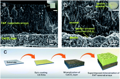
Fig. 1a shows the fabrication procedure of the FAP/CaCO3 heterogeneous structures inspired by teeth. Briefly, 1 wt% chitosan (CS) solution was spin-coated onto a clean slide glass followed by immersion in sodium hydroxide solution (pH = 9) (see the Experimental section). The glass slide was then transferred into a Ca2+ solution with Mg2+ and PAA. Layered CaCO3 was fabricated via slow dripping of a solution containing carbonate ions using a peristaltic pump. Subsequently, the CaCO3 layer together with the underlying CS thin film was transferred into a Ca2+ solution again after being rinsed with purified water. After mineralization for 96 h using a peristaltic pump, enamel-like fluorapatite columnar nanorod arrays were successfully grown on the CaCO3 layer.The cross-sectional scanning electron microscopy (SEM) characterization of the composite reveals a continuous, bi-layered heterogeneous structured thin film with a uniform thickness of approximately 9 μm (Fig. 1a). The synthetic films show remarkable structural similarity to their biogenic counterpart (Fig. 1b). The detailed sketch of a human tooth is shown in Fig. S1.† Fig. 1a reveals a clear interface between the underlying CaCO3 layer and the upper columnar fluorapatite nanorod arrays. The scanning electron microscopy (SEM) images show that the structure of the CaCO3 layers is composed of about 50 nm nanoparticles that are tightly bonded by organic matter. The average thickness of the CaCO3 layers was 3 μm. The morphology of the CaCO3 layers before the mineralization of calcium phosphate is shown in Fig. S2.† The surface of the CaCO3 layer is very smooth, and it is composed of 50 nm nanoparticles, which indicates that it maintains its original structure in the process of further mineralization. The calcium carbonate layer's surface is very flat, which provides a good condition for the superimposed mineralized FAP nanorod array layer. The upper columnar fluorapatite arrays comprise highly oriented thin nanorods that were tightly bound without any gaps. Near the interface, the FAP layer shows a granular structure, and the rod structure becomes more obvious as the height increases. This granular transition structure means that the CaCO3 layers and FAP columnar layer are closely bound. The average thickness of the fluorapatite layer is approximately 6 μm.
In order to explore the influencing factors of interfacial interaction of the heterostructure and find the best synthetic strategy, CaCO3/FAP heterogeneous structured composites were also synthesized (Fig. S3†). We first mineralized a layer of FAP columnar nanorod arrays after 96 h using a peristaltic pump, and then, mineralized layered CaCO3 was superimposed on the FAP arrays. The planar SEM images show that the upper CaCO3 layer is composed of 30 nm nanoparticles and the surface is flat (Fig. S3a and b†). The cross-sectional SEM images reveal that a 2 μm thick calcium carbonate layer was grown on the FAP arrays. However, the combination of the two layers at the interface is not closed. The gap of the nanorods at the interface is not filled by the nanoparticles of calcium carbonate, leaving a relatively large gap. This is because the surface roughness of the nanorod array is considerable, and the calcium carbonate layer is difficult to coat closely at the interface.
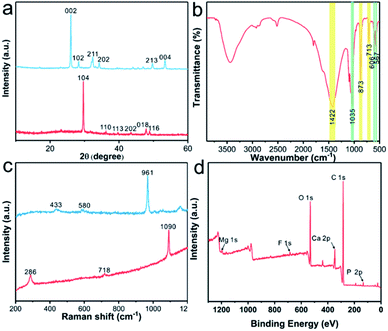
Fig. 2a presents the X-ray diffraction (XRD) patterns of the original CaCO3 layers (red line) and FAP/CaCO3 heterogeneous structured composites (blue line). The characteristic peak detected at 29.5° in the XRD pattern of the CaCO3 layers was the (104) diffraction peak of calcite, and all the remaining diffraction peaks correspond to calcite. In the XRD pattern of the FAP/CaCO3 composites (blue line), the characteristic peak detected at 26.0° corresponded to fluorapatite, and the characteristic peak of calcite disappeared. This means that the FAP nanorod array entirely covers the original calcium carbonate layer in the second mineralization step. When there are holes in the FAP array, calcite and fluorapatite diffraction peaks appear simultaneously (Fig. S4†). Moreover, the intensities of the (002) diffraction peaks were significantly higher than those of the other diffraction peaks, thereby demonstrating preferential growth of the FAP nanorod arrays along the c-axis. This was consistent with the results of the SEM analysis. In the FT-IR spectra of the FAP/CaCO3 heterogeneous structured composites (Fig. 2b), the asymmetric stretching in the vibration band of the C–O group appeared at 1422 cm−1, and the peaks around 873 cm−1 and 713 cm−1 correspond to deformation in the vibration bands of the C–O group in calcite.19,20 The bands at 567 cm−1 and 606 cm−1 correspond to the ν4 bending modes of PO43−.21 In addition, the band at approximately 1035 cm−1 corresponded to the ν3 bending mode of PO43−.22 Fig. 2c shows the Raman spectra of the CaCO3 layers (red line) and FAP/CaCO3 heterogeneous structured composites (blue line). The characteristic peaks at 286, 718, and 1090 cm−1 are the characteristic peaks of calcite.23 The high-intensity characteristic peak at 961 cm−1 was indicative of the highly ordered FAP crystalline arrays. The XPS spectra (Fig. 2d) were analyzed to acquire the chemical status of the FAP/CaCO3 composites. The XPS spectrum of the composites exhibits peaks corresponding to O, P, Ca, C, F, and Mg, revealing the presence of CaCO3 and Ca5(PO4)3F in the composites. The high-resolution XPS profiles are presented in Fig. S5.† The C 1s spectrum can be divided into three peaks located at the binding energies of 288.80 eV, 286.1 eV and 284.8 eV, which are respectively attributed to CO32− and the oxygen-bound bonds C–(O, N) and C–C.24,25 The Ca 2p spectrum consists of two peaks with binding energies of 350.8 and 347.3 eV, corresponding to Ca 2p1/2 and Ca 2p3/2, which are in agreement with the Ca2+ oxidation state.26,27 The F 1s spectrum exhibits a symmetric peak at 684.5 eV (Fig. S5†).28 The P 2p spectrum presents two deconvoluted peaks at 132.9 and 134 eV,29,30 (Fig. S5†) and almost no magnesium was detected because of its negligible amount.
Fig. 3 shows the SEM-EDS mapping of the FAP/CaCO3 heterogeneous structured composites. Fig. 3a shows the heterogeneous structures of the underlying layered CaCO3 and upper columnar fluorapatite nanorod arrays. Fig. 3b–g present the EDS mapping of O, F, P, C, Mg, and Ca. In the elemental distribution of P, O, and C, we can see an obvious dividing line between FAP and CaCO3. There are more O and C and less P atoms in the CaCO3 layer than in the FAP arrays. The content of each element is shown in Fig. 3h.
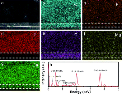 | ||
| Fig. 3 SEM image (a), EDS mapping (b–g) and EDS profile (h) of the FAP/CaCO3 heterogeneous structured composites. | ||
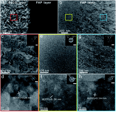
In order to reveal the internal structure of the FAP/CaCO3 heterogeneous structured composite, the samples were treated with a focused ion beam (FIB). Fig. 4a shows the boundary between the CaCO3 layer and FAP layer. It can be found that near the boundary, the FAP layer shows a granular structure, where the particle size is about 20 nm, and the rod structure becomes more obvious as the height increases (Fig. 4b). The red, yellow and blue boxes show the details of the CaCO3 layer, the FAP granular transition area and the FAP nanorod array area, respectively (Fig. 4c–h). The underlying layer is CaCO3 assembled by nanoparticles (Fig. 4c and d). The high-resolution transmission electron microscopy (HRTEM) image shown in Fig. 4d and the inset selected area electron diffraction (SAED) pattern shows that the small particles in the calcium carbonate layer crystallized very well. The upper layer is the FAP layer with a granular region and arrays in a closely arranged columnar structure. HRTEM images are also shown in Fig. 4f and h. The nanorods in the FAP layer exhibit single-crystal properties (Fig. 4h).
3.2 Mechanical properties of the FAP/CaCO3 heterogeneous structured composites
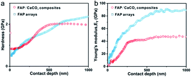
Nanoindentation measurements were employed to measure the hardness (H) and Young's modulus (EY) values of the synthetic FAP/CaCO3 heterogeneous structured composites. In order to avoid substrate and surface effects, the H and EY of our composites were measured by the continuous stiffness measurement (CSM) method with Berkovich probes at a depth of 900 nm, which did not exceed 10% of the total thickness. The synthetic FAP/CaCO3 heterogeneous structured composite films exhibit H and EY values of 1.99 ± 0.02 GPa and 47.5 ± 0.6 GPa, respectively (Fig. 5a and b), which were comparable to those of natural teeth. These properties should be attributed to the structural continuity between the FAP layer and the CaCO3 layer. When the whole composite is subjected to an external force, energy will pass through the nanorod array to the granular calcium carbonate layer with higher organic content (4.5 wt%) than that in the FAP arrays (Fig. S6†), and dissipate more energy to prevent the whole material from being destroyed. The synthetic FAP/CaCO3 heterogeneous structured composites contain as much as 96.6 wt% inorganic components, which is quite comparable to that of natural teeth. Load–displacement curves are shown in Fig. S7.† Since the FAP arrays are arranged more closely, the mechanical properties of these synthetic FAP/CaCO3 heterogeneous structured composites are lower than that of FAP arrays.31 Table S1† presents other synthetic calcium phosphate and calcium carbonate materials.4. Conclusions
In summary, FAP/CaCO3 heterogeneous structured composites with a tooth-like structure were successfully fabricated using a three-step mineralization method under ambient temperature. Inspired by the hierarchical architecture of teeth, we firstly grew a calcite calcium carbonate layer on the surface of chitosan (CS) films under the coordinated control of magnesium ions (Mg2+) and polyacrylic acid (PAA). Subsequently, we grew FAP columnar nanorod arrays on the calcium carbonate layer via superimposed mineralization. The granular transition structure near the interface means that the CaCO3 layers and FAP columnar layer are closely bound. The granular calcium carbonate layer with higher organic content (4.5 wt%) than that of the FAP arrays (3.4 wt%) can dissipate more energy to prevent the whole material from being destroyed. The hardness and Young's modulus of the synthetic FAP/CaCO3 heterogeneous structured composites are 1.99 ± 0.02 GPa and 47.5 ± 0.6 GPa, respectively, which are comparable to those of natural teeth. We expect that this general strategy has broad applicability for preparing various multi-scale heterogeneous structured composite materials with unique functionalities under ambient conditions.Author contributions
Li YD conducted the experiments and wrote the paper. Wang K and Fu ZY supervised the project. Zhou ZY, Ping H and Xie JJ guided the theoretical analysis part. Lei LW and Wang WM revised the paper. All authors contributed to the general discussion.Conflicts of interest
There are no conflicts to declare.Acknowledgements
This work was financially supported by the National Key Research and Development Program of China (2021YFA0715700) and the National Natural Science Foundation of China (51832003). The authors would like to thank Miss Ting-ting Luo (Center for Materials Research and Analysis, Wuhan University of Technology) for her help in the HRTEM analysis.Notes and references
- M. J. Buehler, Nano Today, 2010, 5, 379–383 CrossRef CAS.
- G. X. Gu, M. Takaffoli and M. J. Buehler, Adv. Mater., 2017, 29, 1700060 CrossRef PubMed.
- W. Yang, H. Quan, M. A. Meyers and R. O. Ritchie, Matter, 2019, 1, 1557–1566 CrossRef.
- E. A. Zimmermann, B. Gludovatz, E. Schaible, N. K. Dave, W. Yang, M. A. Meyers and R. O. Ritchie, Nat. Commun., 2013, 4, 1–7 Search PubMed.
- X. Li, W.-C. Chang, Y. J. Chao, R. Wang and M. Chang, Nano Lett., 2004, 4, 613–617 CrossRef CAS.
- C. Xiao, M. Li, B. Wang, M.-F. Liu, C. Shao, H. Pan, Y. Lu, B.-B. Xu, S. Li and D. Zhan, Nat. Commun., 2017, 8, 1–9 CrossRef CAS PubMed.
- J. J. Xie, H. Ping, T. N. Tan, L. W. Lei, H. Xie, X. Y. Yang and Z. Y. Fu, Prog. Mater. Sci., 2019, 105, 100571 CrossRef.
- S. Mann, Biomineralization: Principles and Concepts in Bioinorganic Materials Chemistry, Oxford University Press on Demand, 2001 Search PubMed.
- W. D. Kingery, H. K. Bowen and D. R. Uhlmann, Introduction to Ceramics, John Wiley & Sons, 1976 Search PubMed.
- L. Wu, Y. Li, Z. Fu and B.-L. Su, Natl. Sci. Rev., 2020, 7, 1667–1701 CrossRef CAS PubMed.
- A. R. Studart, F. Filser, P. Kocher and L. J. Gauckler, Dent. Mater., 2007, 23, 106–114 CrossRef CAS PubMed.
- J. R. Kelly, Annu. Rev. Mater. Sci., 1997, 27, 443–468 CrossRef CAS.
- L. H. He and M. V. Swain, J. Mech. Behav. Biomed. Mater., 2008, 1, 18–29 CrossRef PubMed.
- C. Chen, Z. Wang, M. Saito, T. Tohei, Y. Takano and Y. Ikuhara, Angew. Chem., 2014, 126, 1569–1573 CrossRef.
- S. Bentov, P. Zaslansky, A. Al-Sawalmih, A. Masic, P. Fratzl, A. Sagi, A. Berman and B. Aichmayer, Nat. Commun., 2012, 3, 1–7 Search PubMed.
- R. Wang, L. Addadi and S. Weiner, Philos. Trans. R. Soc. London, Ser. B, 1997, 352, 469–480 CrossRef CAS PubMed.
- B. Yeom, T. Sain, N. Lacevic, D. Bukharina, S.-H. Cha, A. M. Waas, E. M. Arruda and N. A. Kotov, Nature, 2017, 543, 95–98 CrossRef CAS PubMed.
- J. Wei, H. Ping, J. Xie, Z. Zou, K. Wang, H. Xie, W. Wang, L. Lei and Z. Fu, Adv. Funct. Mater., 2020, 30, 1904880 CrossRef CAS.
- D. Azizi and F. Larachi, Colloids Surf., A, 2018, 537, 126–138 CrossRef CAS.
- T. Wang, B. Feng, Y. Guo, W. Zhang, Y. Rao, C. Zhong, L. Zhang, C. Cheng, H. Wang and X. Luo, Miner. Eng., 2020, 159, 106635 CrossRef CAS.
- K. Tank, P. Sharma, D. Kanchan and M. Joshi, Cryst. Res. Technol., 2011, 46, 1309–1316 CrossRef CAS.
- L. Berzina-Cimdina and N. Borodajenko, Infrared Spectrosc.: Mater. Sci., Eng. Technol., 2012, 12, 251–263 Search PubMed.
- I. K. Shaik, L. Zhang, S. Pradhan, A. K. Kalkan, C. P. Aichele and P. K. Bikkina, J. Pet. Sci. Eng., 2021, 198, 108231 CrossRef CAS.
- J. Yang, J. Cui, A. Xie, J. Dai, C. Li and Y. Yan, Colloids Surf., A, 2021, 608, 125583 CrossRef CAS.
- F. Scalera, A. G. Monteduro, G. Maruccio, L. Blasi, F. Gervaso, E. Mazzotta, C. Malitesta and C. Piccirillo, Sustainable Mater. Technol., 2021, 28, e00260 CrossRef CAS.
- S. Sun, H. Ding, X. Hou, D. Chen, S. Yu, H. Zhou and Y. Chen, Appl. Surf. Sci., 2018, 456, 923–931 CrossRef CAS.
- H. Xiong, J. Chen, T. Zhang, W. Wang, C. Huang, Y. Zhu and B. Hu, J. Mol. Liq., 2021, 322, 114986 CrossRef CAS.
- J. Xu and K. A. Khor, J. Inorg. Biochem., 2007, 101, 187–195 CrossRef CAS PubMed.
- C. L. Popa, A. Deniaud, I. Michaud-Soret, R. Guégan, M. Motelica-Heino and D. Predoi, J. Nanomater., 2016, 1062878 Search PubMed.
- J. Wu, K. Ueda and T. Narushima, Mater. Sci. Eng., C, 2020, 109, 110599 CrossRef CAS PubMed.
- Y. D. Li, H. Ping, J. J. Wei, Z. Y. Zou, P. C. Zhang, J. J. Xie, Y. H. Jia, H. Xie, W. M. Wang, K. Wang and Z. Y. Fu, ACS Appl. Mater. Interfaces, 2021, 13, 25260–25269 CrossRef CAS PubMed.
Footnote |
| † Electronic supplementary information (ESI) available. See https://doi.org/10.1039/d2ra00374k |
| This journal is © The Royal Society of Chemistry 2022 |

