 Open Access Article
Optimized nano-metal particles filled into carbon nanohorns to achieve high N-doping amount and high porosity for enhanced oxygen evolution reaction†
Yanli Nan * and
Zhaoyu Wang
School of Material Science and Engineering, Shaanxi Key Laboratory of Nano Materials and Technology, Xi'an University of Architecture and Technology, Xi'an, 710055, China. E-mail: nanyl@xauat.edu.cn
First published on 7th April 2022
Abstract
Nano-metal-filled N-doped carbon materials have been actively verified as promising alternatives for precious-metal catalysts in the oxygen evolution reaction (OER). Herein, Ni/Fe/Cu-filled N-doped carbon nanohorns (CNHs) are synthesized via a positive pressure assisted arc discharge method using a Ni/Fe/Cu rod charged in an anode hole in a N2 and Ar mixture. We first found that the amount of N atom doping can be controlled by the types of nano-metal particles encapsulated by CNHs. The content of N atoms on CNHs uniquely depended on the initial Ni wires inserted into the anode graphite; increasing the number of Ni wires induced the enrichment of N atoms until 3.56 at%, whereas the content of N atoms for Cu- and Fe-filled CNHs is against the results; loading Cu and Fe nanoparticles decreases the N-doping amount. And the morphologies and N-configurations can be changed by the types of metal nanoparticles. Furthermore, the OER performance of Ni-filled CNHs is much superior to that of Cu- and Fe-filled CNHs, which can be significantly enhanced by the tip opening structure, and the increase in Ni loading amount and the N atom content.
Introduction
The oxygen evolution reaction (OER) is coupled with numbers of key renewable energy systems such as solar cells, metal–air batteries and water splitting.1–3 However, the OER process is kinetically sluggish caused by a complex four-electron/proton transfer process. Although noble metal oxides such as IrO2 and RuO2 show excellent catalytic performance for OER, their widespread development is restricted by the high cost and scarcity.4–7 Recently, metal nanoparticles supported on carbon materials have attracted considerable interest due to the excellent conductivity and high catalyst loadings.8–10 For example, the incorporation of Ni, Fe, and Co nanoparticles into N-doped carbon materials in catalysts exhibits remarkable catalytic efficiency, together with the high stability according to the previous reports.8,9 Previous research also showed that the conductivity of carbon nanomaterials can be obviously improved when N atoms are added into the carbon nanomaterials by providing the catalytic sites. Besides, the N atoms and metal nanoparticles can have synergistic effects to enhance the OER performance.11,12 However, the relatively low N-doping efficiency limits the wide use. With respect to the popular carbon materials such as graphene and carbon nanotubes (CNTs), it is a great challenge to design N-doped carbon materials dispersed with nano-metal nanoparticles with optimized structures and enhanced catalytic performance for next generation OER applications.It is widely known that carbon nanohorns (CNHs) can be a catalytic carrier/catalyst in numerous electrochemical energy generation systems due to their excellent electronic conductivity, superb mechanical properties, nanoporous characteristics, and high specific surface area (SSA) after post-treatments.13–15 In general, CNHs are constructed by thousands of individual CNH by the self-assembling mechanism to form aggregates with 80–100 nm diameters. The individual CNH consists of cone-shaped tips with 40–50 nm length and 2–3 nm diameter. Although metal nanoparticles like Pt, Ni, Cu, Zn, and Fe can be uniformly distributed into the individual CNH tube by the modified gas-injected arc-in-water method in N2 reported by Sano et al.,16,17 the individual CNH exhibits a tip-closed structure with low SSA and poor porosity, which is harmful to the OER performance. Notably, there is no N-doping on these CNHs, maybe due to the existence of water hindering the ionization of nitrogen gas. Therefore, it is urgent to find a new method to improve the amount of N-doping for nano-metal-filled CNHs. To the best of our knowledge, despite considerable attention focused on the CNHs, research on N-doped CNHs dispersed with nano-metal nanoparticles used for the OER is rare.
In this study, the N-doped CNHs dispersed with Ni/Fe/Cu nanoparticles were produced via arc discharge by introducing the N2 at positive pressure. The relationship among the morphologies, the N-doping amount and N-configurations for Ni/Fe/Cu-filled CNHs are explored in this experiment. Besides, the effect of the amount of Ni-loading on the content of N atoms is studied. Finally, the OER performance for Ni/Fe/Cu-filled CNHs is compared. In full consideration, Ni-filled CNHs possess remarkable OER performance, attributing to the high loading amount of N atoms and Ni nanoparticles, and the optimized morphology for CNHs.
Experimental section
Synthesis of N-doped CNHs dispersed with Ni nanoparticles
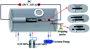
CNH samples are prepared by the positive pressure assisted arc plasma method in an Ar (0.10 MPa) and N2 (0.05 MPa) mixture. The schematic diagram of arc discharge equipment is illustrated in Fig. 1. The anode was made in pure graphite rod (diameter = 6 mm and length = 200 mm) to produce N-doped CNHs. When used a graphite rod with a hole of 1 mm in diameter to fill one Ni/Fe/Cu wire with a diameter of 0.2 mm as the anode, CNHs dispersed with metal nanoparticles can be obtained, denoted as 1-Ni-, 1-Fe- and 1-Cu-filled CNHs. Besides, two holes and three holes of 1 mm diameter were drilled along its axis to charge Ni wires, respectively, referred to as 2- and 3-Ni-filled CNHs.The analyses of the prepared products
The morphologies were observed using a transmission electron microscope (TEM, JEOL, JEM-2010F). X-ray diffraction (XRD) apparatus (Rigaku, RINT2100) equipped with Cu Kα radiation was used to obtain the phase and crystal characteristics. X-ray electron spectrum (XPS) equipment was used to determine the chemical state and the types of elements on the surface of the as-prepared samples. Pore size distribution and SSA were studied in N2 adsorption isotherm condition at 77 K by the Brunauer–Emmett–Teller (BET) method.Electrochemical testing
The electrochemical results were measured using a three-electrode system combined with an electrochemical workstation (CS350, Shanghai Sikete Instrument). Carbon fiber paper (CFP) coated with a CNH mixture, Hg/HgO (salt bridge protection) and platinum wire electrodes were used as the working electrode, counter electrode and reference electrode, respectively. 5 mg sample was dissolved in 7 μL Nafion solution (5%) as a binder. Then they were put in 300 μL of ethanol and sonicated for 30 minutes to get a good dispersion in the solution and coated on the CFP with a 1 cm × 1 cm spatula. Finally, they were dried in a vacuum oven at 80 °C for 30 minutes.Results and discussion
The morphologies and the structures of Ni-, Fe-, and Cu-filled CNHs
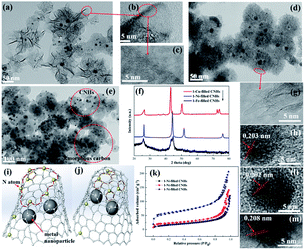
The TEM images of 1-Ni-, 1-Fe-, and 1-Cu-filled CNHs are shown in Fig. 2. These figures suggest that the Ni, Fe and Cu nanoparticles are well dispersed into CNHs, indicated by the dark spots. Notably, we can see that the morphology of 1-Fe-filled CNHs (in Fig. 2(d)) has no significant change in horn structure compared with “dahlia-like” aggregates,18,19 which are tubular structures with cone shaped caps distributed with pentagonal and heptagonal defects as illustrated in Fig. 2(g). By HRTEM observations in Fig. 2(a), we can see that the morphology of 1-Ni-filled CNHs is against the traditional reported dahlia-CNHs with 20° cone-closed caps, where the periphery of CNHs is composed of the opening caps, similar to the few-layer curled graphene as depicted in Fig. 2(b) and (c). When a Cu wire is inserted into the anode graphite, a considerable part of production is the amorphous carbon as shown in Fig. 2(e), the purity of Cu-filled CNHs is much lower than that of the other samples, and only a few CNHs remain. The models of the individual tube for Ni- and Fe-filled CNHs are vividly described in Fig. 2(i) and (j), respectively. Note that the arc temperature distribution is a very important factor to determine the morphologies and the structures of the production. The melting point and boiling point of the metal nanoparticles can affect the arc temperature distribution, which induce various morphologies of Ni-, Fe-, and Cu-filled CNHs.Furthermore, by counting over 300 particles from TEM images, the size distribution histograms of metal nanoparticles of 1-Ni-filled, 1-Fe-filled CNHs and 1-Cu-filled CNHs were obtained, as displayed in Fig. S1 in the ESI.† And the average sizes of 1-Ni-N-CNHs, 1-Fe-N-CNHs and 1-Cu-N-CNHs are calculated to be 9.81 nm, 9.71 nm and 8.66 nm, respectively.
XRD analysis was performed on CNHs dispersed with Ni, Fe and Cu as illustrated in Fig. 2(f). All samples show a broad diffraction peak around 26°, indicating a (002) plane of graphitic carbon. Ni, Fe and Cu nanoparticles as indicated by the peaks at 44.3°, 51.6°, 76.1°, and 44.5°, and 42.9°, 50.1°, 73.6°, respectively, reveal that Ni, Fe and Cu nanoparticles are dispersed into CNHs. From HRTEM images in Fig. 2(h, l and m), it could be clearly observed that the lattice fringes are 0.203, 0.202, and 0.208 nm, corresponding to the characteristic of the distance fringe spacing for Ni, Fe and Cu nanoparticles, which is in agreement with the results of HRTEM.
The adsorption/desorption isotherms of nitrogen at 77 K on the 1-Ni-, 1-Fe- and 1-Cu-filled CNHs are illustrated in Fig. 2(k). In this surface area analysis, the values of SSA for 1-Ni-, 1-Fe- and 1-Cu-filled CNHs are calculated to be 223.7, 106.6, and 88.3 m2 g−1, respectively. For 1-Fe- and 1-Cu-filled CNHs, only interstitial pores between the individual CNH contribute to the value of SSA. Notably, the part of amorphous carbon in the production of 1-Cu-filled CNHs decreases their SSA. In contrast to 1-Fe- and 1-Cu-filled CNHs, the SSA of 1-Ni-filled CNHs is much higher, suggesting that the internal spaces for the individual CNH can contribute to the value of SSA caused by the tip opening structure for individual CNHs, exhibiting the excellent porosity.
XPS analysis
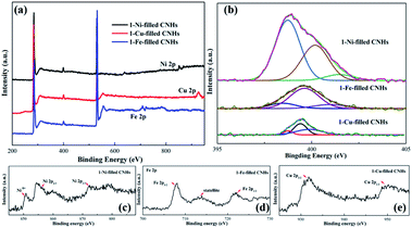
Herein, XPS was used to reveal the chemical signature of the elements and to obtain the amount of N-doping. As depicted in Fig. 3, C1s, N1s and O1s peaks appear at ∼284.5, ∼399.5, and ∼532.7 eV, confirming the presence of nitrogen as well as carbon and oxygen within the aggregates. The O atoms may be due to the sample exposure in air.24 The N1s spectra can be decomposed into three peaks centered at 388.3–399.0 eV, 399.0–400.0 eV and 400.0 ± 401.6 eV, corresponding to the pyridinic-N, pyrrolic-N, and graphite-N, respectively.24,25After calculation, when Ni nanoparticles dispersed into CNHs, the N-doping amount enhanced sharply up to 2.53 at%. It is noticeable that this relationship between the Cu/Fe nanoparticle and the N atom content is opposite to the case of Ni nanoparticles. In fact, Cu and Fe loading decreases the N atom content with 1.23 at% and 1.53 at% N-doping, respectively. We reveal the relationship between the content of N atoms and the types of the elemental metal nanoparticles by positive pressure assisted arc discharge.
As shown in Fig. 3(b), the N1s peak is decoupled into three fitted peaks ranging from 388.3 to 401.0 eV. Furthermore, the atomic percentage (AP) of pyridinic-N for 1-Ni-filled CNHs can reach up to 76.3%, indicating that most of the N atoms are linked with two coordinated C atoms at the edges and defects for Ni-filled CNH tubes.
In contrast to the 1-Ni-filled CNHs, the AP of pyrrolic-N for 1-Fe- and 1-Cu-filled CNHs has ∼70% contributions to the N configurations, suggesting that most of N atoms bond to two C atoms to form the five-membered ring.
According to the previous reports,26 the bond length of C–N (1.41 Å) for pyridinic- and graphitic-N is similar to that of the C–C bond (1.42 Å). Thus, pyridinic- and graphitic-N are inclined to form a plane structure rather than a curved structure. Notably, pyrrolic-N dopants with a shorter C–N bond length (1.37 Å) easily cause compressive strain and stress field, which tend to form pentagonal and heptagonal rings.27 Namely, pyrrolic-N is helpful for the formation of the cone shaped structure, and pyridinic-N is conducive to forming the plane structure. It should be noted that few pyrrolic-N is needed to form the cone shaped structure as depicted in the model of 1-Fe- and 1-Cu-filled CNHs in Fig. 2(i) and (j). Therefore, the pyridinic-N plays a critical role in the N-doping amount.
Those analysis conclusions are consistent with the HRTEM observations; the N-doped CNHs, and 1-Ni-filled CNHs show a tip-half closed structure with pyridinic-N enrichment but few pyrrolic-N, whereas CNHs dispersed with Fe and Cu nanoparticles present a tip-closed structure with the closed horn-cap being rich in pyrrolic-N. Although the structure and the types of N-configurations for 1-Fe-filled CNHs are similar to those for the 1-Cu-filled CNHs, the N-doping content is much higher than that in 1-Cu-filled CNHs. Those results suggest that the purity affects the N-doping amount; the lower the purity, the lower the N-doping amount. As a result, the types of metal nanoparticles affect the content of N-doping by changing the N-conformations and the morphologies of CNHs.
Furthermore, the high-resolution spectra of Ni, Fe, and Cu peaks of 1-Ni-, 1-Fe-, and 1-Cu-filled CNHs are provided in Fig. 3(c). Two peaks emerging at 872.9 eV and 854.6 eV correspond to the Ni 2p1/2 and Ni 2p3/2, and the other peaks at 861.2 eV and 877.8 eV represent their satellite peaks, representing the metallic Ni. Three peaks appearing at 721.7, 7195.1, and 707.3 eV correspond to Fe 2p1/2, satellite, and Fe 2p3/2, respectively, which represents the metallic Fe. The high-resolution Cu 2p spectrum exhibits three peaks at 952.1 and 932.2 eV corresponding to Cu 2p1/2, satellite, and Cu 2p3/2, respectively, corresponding to the binding energies of metallic Cu.
Raman analysis
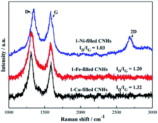
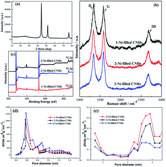
Two notable peaks at ∼1351 and ∼1582 cm−1 appear simultaneously for 1-Ni, 1-Fe and 1-Cu-filled CNHs as depicted in Fig. 4 named D and G bands. The intensity of the D band can be controlled by the structural defects.20 In a normal first-order Raman scattering process, the phonon vibrations in the sp2 carbon material are represented by the G band. Calculated by the Tuinstra and Koenig equation, the nanocrystalline size or defect density for graphitic nanostructures can be obtained by the ratio of ID to IG.21,22 As illustrated in Fig. 4, the ratio of ID to IG for 1-Ni-filled CNHs is 1.03, which is much smaller than that of the 1-Fe-filled CNHs (1.20) and 1-Cu-filled CNHs (1.32). This result suggests that less defects exist on the 1-Ni-filled CNHs. Notably, the result is against the common scene, the more the hetero-atom doping the more the defect degree. It is well known that pentagonal and heptagonal defects are the essential conditions to form the cone-shaped cap for CNHs. This result indicates that with increasing the N-doping content, the cone-shaped cap structure for CNHs tends to transform the plane structure, which is in agreement with the HRTEM observation. Moreover, relative to the 1-Fe and 1-Cu-filled CNHs, 1-Ni-filled CNHs show a protruding 2D peak, suggesting that the part structure of 1-Ni-filled CNHs is similar to the graphene sheets.23In order to obtain the effect of the Ni-loading amount on the content of N atoms for the CNHs, two and three Ni wires are inserted into the anode during arc discharge. The products are named 2-Ni-filled CNHs and 3-Ni-filled CNHs. Then the 1/2/3-Ni-filled CNH samples are oxidized by O2 in a tube furnace at 900 °C for 3 hours, respectively. From the XRD result as illustrated in Fig. 5(a), we can see that the remaining powder is Ni nanoparticles and the peak for CNHs is nearly not detected. After calculation, the weight of the remaining Ni for 1-Ni-filled CNH, 2-Ni-filled CNHs and 3-Ni-filled CNHs is obtained to be ∼9, ∼13, and ∼18 wt%, respectively. Consequently, the Ni-loading amount in the Ni-filled CNHs was varied by changing the number of Ni wires inserted into the anode. In the same method, the loading amount of Fe and Cu of 1-Fe-filled CNHs, and 1-Cu-filled CNHs can be calculated. In general, Fe and Cu are transformed to Fe2O3 and CuO,18 respectively. The Fe and Cu loading amounts (wt%) of 1-Fe-filled CNHs, and 1-Cu-filled CNHs were calculated to be 8.5, and 9.3 wt%, respectively.
The Raman spectra (in Fig. 5(b)) illustrate that no significant change can be observed in the feature of D, G, and 2D peaks among the 1-Ni-filled CNH, 2-Ni-filled CNHs and 3-Ni-filled CNHs, which indicates that the main structure for the samples is similar to each other.
Interestingly, we found that with increasing the Ni loading amount, the N-doping amount increased significantly as shown in Fig. 5(c). The N-doping amounts of 2-Ni-filled CNHs and 3-Ni-filled CNHs are calculated to be 3.45 at%, and 3.65 at%, respectively. In other words, the content of N atoms on Ni-filled CNHs can be tuned by simply changing the loading amount of Ni nanoparticles. Notably, compared to the 2-Ni-filled CNHs, the N-doping amount for 3-Ni-filled CNHs is slightly larger than that of the 2-Ni-filled CNHs, indicating that the content of N atoms nearly reaches saturation.
As shown in Fig. 5(d) and (e), the pore size distribution in the micropore and mesopore ranges of Ni-filled CNHs is obtained by the t-plot method. The mesopores in the range of 3 to 4 nm come from the internal spaces of the individual CNH caused by the cap opening structure of CNH, which are identical to the diameter of each individual CNH. And, the interstitial pores between the individual CNH are donated to the micropores. It can be seen that the main-peak positions of micropores and mesopores are similar to each Ni-filled CNH sample, which also indicates that the main structure of the Ni-filled samples is similar to each other. Furthermore, as depicted in Fig. 5(e), the mesopore volumes become larger with increasing the Ni loading amount, indicating that much more cap opening structures of CNH are produced. As a result, the numbers of pyridinic-N and the content of N doping can be improved, which are linked with two coordinated C atoms at the edges and defects of Ni-filled CNH tubes.
The formation mechanism of THC-N-CNHs
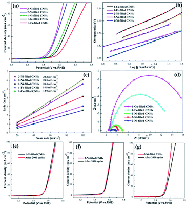
To obtain the OER kinetics for the as-prepared samples, the Tafel slopes were evaluated based on the LSV curves. The lowest Tafel slope for 3-Ni-filled CNHs (65 mV dec−1) reveals appropriate kinetic and superior catalytic activity (Fig. 6(b)). The Tafel slopes of 2-Ni-filled CNH and 1-Ni-filled CNH catalysts were about 67 mV dec−1 and 76 mV dec−1 (Fig. 6(b)), much smaller than that of the 1-Cu-filled CNHs (100 mV dec−1) and 1-Fe-filled CNHs (89 mV dec−1), which further confirmed the superior electrocatalytic OER performance of Ni-filled CNHs.
By measuring the value of double layer capacitance (Cdl) of the catalysts, the electrochemically active surface area (ECSA) can be evaluated,29,32 because the ECSA is positively proportional to the Cdl. And, the half of the slope value represents the Cdl value. The 3-Ni-filled CNHs show the largest Cdl of 30.2 mF cm−2 which can be seen in Fig. 6(c), which is slightly larger than that of 2-Ni-filled CNHs (28.5 mF cm−2), but more than 1.40 times that of 1-Ni-filled (20.3 mF cm−2), indicating that more active sites can be exposed by increasing the Ni-loading amount and the content of N atoms. Notably, the Cdl value for 1-Fe-filled CNHs (14.8 mF cm−2) is much lower than that of the Ni-filled CNHs. Those results suggest that the morphologies for catalyst carriers significantly influence the value of the ECSA, and the tip opening structure induces much more active sites exposed.
The electron transfer rate between the catalyst/electrolyte interface can be analyzed by the EIS measurements.33,34 In general, the value of charge-transfer resistance (Rct) can be measured by the diameter of the Nyquist plot with a semicircle feature; the smaller the Rct, the more favorable the electrocatalytic kinetics. The Rct value of 3-Ni-filled CNHs is 1.5 Ω, which is much smaller than that of 1-Ni-filled CNHs (2.7 Ω), and 2-Ni-filled CNHs (1.7 Ω) as depicted in Fig. 6(d), suggesting that 3-Ni-filled CNHs hold much more efficient electron transfer frequency and better catalytic activity during the OER process than 1-Ni-, and 2-Ni-filled CNHs.
The TOF values of the as-prepared catalysts were calculated through the following equation:
![[thin space (1/6-em)]](https://www.rsc.org/images/entities/char_2009.gif) 500C mol−1 stands for the Faraday constant, and n (mol) represents the number of moles of Ni and N atoms loaded on the catalyst surface which was determined by the XPS analysis, because the performance of the catalyst is mainly related to the types and states of the surface elements.35,36 The TOF values of the 1-Ni-filled-CNHs, 2-Ni-filled-CNHs and 1-Ni-filled-CNHs are calculated to be 0.0019 S−1, 0.0021 S−1, and 0.0023 S−1, respectively.
500C mol−1 stands for the Faraday constant, and n (mol) represents the number of moles of Ni and N atoms loaded on the catalyst surface which was determined by the XPS analysis, because the performance of the catalyst is mainly related to the types and states of the surface elements.35,36 The TOF values of the 1-Ni-filled-CNHs, 2-Ni-filled-CNHs and 1-Ni-filled-CNHs are calculated to be 0.0019 S−1, 0.0021 S−1, and 0.0023 S−1, respectively.
It is widely known that the durability of electrode materials is one of the major limiting factors for OER application. In this work, to evaluate the long-term durability, 2000 cycles of CV scanning tests were carried out. The value of the overpotential for 1/2-Ni-filled CNHs became slightly larger than that of the initial LSV curve after 2000 CV cycles, which exhibits outstanding electrocatalytic durability for the OER, as displayed in Fig. 6(e) and (f). This result indicates that the Ni nanoparticles located on the N-doped CNHs not only allow for high utilization of active material but prevent the aggregation of Ni after multiple cycles. It should be recognized that in situ synthesis of Ni-filled CNHs has better adherence and corrosion-resistance to keep the nanoparticles steadily exposed. It should be emphasized that N atoms could anchor the Ni nanoparticles caused by the synergistic effects during the OER process. However, 3-Ni-filled CNH shows a big degradation during the stability test after 2000 cycles, indicating that the Ni nanoparticles tend to fall off from CNHs after several cycles. To confirm this point, the magnetic hysteresis loops of the 3-Ni-filled CNHs before 2000 cycles and 3-Ni-filled CNHs after 2000 cycles are obtained, as depicted in Fig. S3 in the ESI.† We can see that the saturation magnetization (Ms) of 3-Ni-filled CNHs after 2000 cycles is much smaller than that of 3-Ni-filled CNHs before 2000 cycles, indicating that 3-Ni-filled CNHs after 2000 cycles exhibit weak magnetism and some Ni nanoparticles of 3-Ni-filled CNHs after 2000 cycles fade off from the CNHs and drop into the electrolyte solution. It should be noted that the OER performance for 3-Ni-filled CNHs after 2000 cycles is similar to that of the 2-Ni-filled CNHs, suggesting that the suitable ratio of Ni-loading amount and N atom content can maintain the long-term stability.
Conclusions
We first reveal that the N-doping amount and the N-configurations can be controlled by the types of metal nanoparticles caused by changing the morphologies of CNHs. The more loading amount of Ni nanoparticles induces the more N-doping amount. And the N atom content can reach the maximum value of 3.65 at% with pyridinic-N enrichment. The enhanced N-doping amount can attribute to the tip opening structure with substantial pyridinic-N of Ni-filled CNHs. The Fe and Cu loading decreases the N-doping amount due to the cone-cap structure reducing the content of pyridinic-N.Besides, the Ni-filled CNHs exhibit notable OER performance compared to that of Fe- and Cu-filled CNHs, which can attribute to the sufficient porosity caused by the tip opening structure, the high N atom content and the high loading amount of Ni nanoparticles. Importantly, the long-term stability of Ni-filled CNHs can be retained at a high level with a suitable ratio of Ni-loading amount and N atom content.
Author contributions
Yanli Nan: conceptualization and writing – original draft. Zhaoyu Wang: data curation.Conflicts of interest
There are no conflicts to declare.Acknowledgements
This work was funded by China Postdoctoral Science Foundation (Grant No. 2020M683671XB).Notes and references
- R. Jeyagopal, Y. F. Chen, M. Ramadoss, K. Marimuthu, B. Wang, W. X. Li and X. J. Zhang, A three-dimensional porous CoSnS@CNT nanoarchitecture as a highly efficient bifunctional catalyst for boosted OER performance and photocatalytic degradation, Nanoscale, 2020, 12, 3879–3887 RSC.
- D. Böhm, M. Beetz, M. Schuster, K. Peters, A. G. Hufnagel, M. Döblinger, B. Böller, T. Bein and D. Fattakhova-Rohlfing, Efficient OER Catalyst with Low Ir Volume Density Obtained by Homogeneous Deposition of Iridium Oxide Nanoparticles on Macroporous Antimony-Doped Tin Oxide Support, Adv. Mater., 2020, 30, 1906670 Search PubMed.
- C. H. Li, E. H. Zhou, Z. Y. Yu, H. X. Liu and M. X. Xiong, Tailor-made open porous 2D CoFe/SN-carbon with slightly weakened adsorption strength of ORR/OER intermediates as remarkable electrocatalysts toward zinc-air batteries, Appl. Catal., B, 2020, 269, 118771 CrossRef CAS.
- D. M. Shao, P. W. Li, R. Z. Zhang, C. H. Zhao, D. Q. Wang and C. J. Zhao, One-step preparation of Fe-doped Ni3S2/rGO@NF electrode and its superior OER performances, Int. J. Hydrogen Energy, 2019, 44, 2664–2674 CrossRef CAS.
- Y. L. Guo, Y. Zhou, Y. L. Nan, B. Li and X. L. Song, Ni-Based Nanoparticles-Embedded N-Doped Carbon Nanohorns Derived from Double Core-Shell CNH@PDA@NiMOF for Oxygen Electrocatalysis, ACS Appl. Mater. Interfaces, 2020, 12, 12743–12754 CrossRef CAS PubMed.
- X. Cao, W. Yan, C. Jin, J. Tian, K. Ke and R. Yang, Surface modification of MnCo2O4 with conducting polypyrrole as a highly active bifunctional electrocatalyst for oxygen reduction and oxygen evolution reaction, Electrochim. Acta, 2015, 180, 788–794 CrossRef CAS.
- Y. Wu, J. Zang, L. Dong, Y. Zhang and Y. Wang, High performance and bifunctional cobalt embedded nitrogen doped carbon/nano diamond electrocatalysts for oxygen reduction and oxygen evolution reactions in alkaline media, J. Power Sources, 2016, 305, 64–71 CrossRef CAS.
- U. Nabi, W. Zhao, X. Lu, J. O. Chidinma, A. S. Sayyar, M. Zhang, J. Xie and Y. Xu, In situ growth of M–MO (M = Ni, Co) in 3D graphene as a competent bifunctional electrocatalyst for OER and HER, Electrochim. Acta, 2019, 298, 163–171 CrossRef.
- S. B. Leticia and M. Gilberto, Developing efficient catalysts for the OER and ORR using a combination of Co, Ni, and Pt oxides along with graphene nanoribbons and NiCo2O4, J. Mater. Chem. A, 2020, 8, 17691–17705 RSC.
- Y. Y. Liu, H. L. Jiang, Y. H. Zhu, X. L. Yang and C. Z. Li, Transition metals (Fe, Co, and Ni) encapsulated in nitrogen-doped carbon nanotubes as bi-functional catalysts for oxygen electrode reactions, J. Mater. Chem. A, 2016, 4, 1694–1701 RSC.
- Y. Qiu, X. Zhang and S. Yang, High performance supercapacitors based on highly conductive nitrogen-doped graphene sheets, Phys. Chem. Chem. Phys., 2011, 13, 12554–12558 RSC.
- S. Chen, J. J. Duan, J. R. Ran, M. Jaroniec and S. Z. Qiao, N-doped graphene film-confined nickel nanoparticles as a highly efficient three-dimensional oxygen evolution electrocatalyst, Energy Environ. Sci., 2013, 6, 3693–3699 RSC.
- O. M. Josue, Z. P. Wang, C. S. Rodolfo, M. G. Aaron, F. Wang, X. D. Yao, T. Mauricio and E. Morinobu, Defect engineering and surface functionalization of nanocarbons for metal-free catalysis, Adv. Mater., 2019, 31, 1–16 Search PubMed.
- X. Wang, M. H. Lou, X. T. Yuan, W. J. Dong, C. L. Dong and H. Bi, Nitrogen and oxygen dual-doped carbon nanohorn for electrochemical capacitors, Carbon, 2017, 118, 511–516 CrossRef CAS.
- Y. L. Nan, L. M. Lei, Z. H. Zhang, B. Li and L. Su, High pressure-induced phase transition in nanocrystalline iron confined by single-walled carbon nanohorns, J. Appl. Phys., 2022, 131, 055901 CrossRef CAS.
- N. Sano, K. Yamada, T. Suntornlohanakul and H. Tamon, Low temperature oxidation of Fe-included single-walled carbon nanohorns in water by ozone injection to enhance porous and magnetic properties, Chem. Eng. J., 2016, 283, 978–981 CrossRef CAS.
- N. Sano, T. Suntornlohanakul, C. Poonjarernsilp, H. Tamon and T. Charinpanitkul, Controlled Syntheses of Various Palladium Alloy Nanoparticles Dispersed in Single-Walled Carbon Nanohorns by one-step formation using an arc discharge method, Ind. Eng. Chem. Res., 2014, 53, 4732–4738 CrossRef CAS.
- Y. L. Nan, Z. H. Zhang, Y. Y. He, J. Wei and Y. Zhou, Optimized Nanopores Opened on N-Doped Carbon Nanohorns Filled with Fe/Fe2O3 Nanoparticles as Advanced Electrocatalysts for the Oxygen Evolution Reaction, Inorg. Chem., 2021, 60, 16529–16537 CrossRef CAS PubMed.
- Y. L. Nan, Y. Y. He, Z. H. Zhang, J. Wei and Y. B. Zhang, Controllable synthesis of N-doped carbon nanohorns: tip from closed to half-closed, used as efficient electrocatalysts for oxygen evolution reaction, RSC Adv., 2021, 11, 35463 RSC.
- A. Reina, X. T. Jia, J. Ho, D. Nezich, H. B. Son, V. Bulovic, M. S. Dresselhaus and J. Kong, Large area, few-layer graphene films on arbitrary substrates by chemical vapor deposition, Nano Lett., 2009, 9, 30–35 CrossRef CAS PubMed.
- H. J. Jung, Y. J. Kim, J. H. Han, M. Yudasaka, S. Iijima, H. Kanoh, Y. A. Kim, K. Kaneko and C. M. Yang, Thermal-treatment-induced enhancement in effective surface area of single-walled carbon nanohorns for supercapacitor application, J. Phys. Chem. C, 2013, 117, 25877–25883 CrossRef CAS.
- T. Yamaguchi, S. Bandow and S. Iijima, Synthesis of carbon nanohorn particles by simple pulsed arc discharge ignited between pre-heated carbon rods, Chem. Phys. Lett., 2004, 389, 181–185 CrossRef CAS.
- Z. H. Ni, Y. Y. Wang, T. Yu and Z. X. Shen, Raman spectroscopy and imaging of graphene, Nano Res., 2008, 1, 273–291 CrossRef CAS.
- N. Li, Z. Wang, K. Zhao, Z. Shi, Z. Gu and S. Xu, Large scale synthesis of N-doped multi-layered graphene sheets by simple arc-discharge method, Carbon, 2009, 48, 255–259 CrossRef.
- S. Y. Yang, K. H. Chang, H. W. Tien, Y. F. Lee, S. M. Li, Y. S. Wang and C. C. Hu, Design and tailoring of a hierarchical graphene-carbon nanotube architecture for supercapacitors, J. Mater. Chem., 2011, 21, 2374–2380 RSC.
- X. W. Wang, G. Z. Sun, P. Routh, D. H. Kim, W. Huang and P. Chen, Heteroatom-doped graphene materials: Syntheses, properties and applications, Chem. Soc. Rev., 2014, 43, 7067–7098 RSC.
- Z. Zafar, Z. H. Ni, X. Wu, Z. X. Shi, H. Y. Nan, J. S. Bai and T. Li, Evolution of Raman spectra in nitrogen doped graphene, Carbon, 2013, 61, 57–62 CrossRef CAS.
- T. Cheng, H. S. Wang, H. F. Wang, Q. Zhang, G. Tian, J. Nie and F. We, Spatially confined hybridization of Nanometer-Sized NiFe hydroxides into nitrogen-doped graphene frameworks leading to superior oxygen evolution reactivity, Adv. Mater., 2015, 27, 4516–4522 CrossRef PubMed.
- R. Li, Z. Wei and X. Gou, Nitrogen and phosphorus dual-doped graphene/carbon nanosheets as bifunctional electrocatalysts for oxygen reduction and evolution, ACS Catal., 2015, 5, 4133–4142 CrossRef CAS.
- Z. Zafar, Z. H. Ni, X. Wu, Z. X. Shi, H. Y. Nan, J. Bai and L. T. Sun, Evolution of Raman spectra in nitrogen doped graphene, Carbon, 2013, 61, 57–62 CrossRef CAS.
- L. W. Zhang, A. Gao, Y. Liu, Y. Wang and J. T. Ma, PtRu nanoparticles dispersed on nitrogen-doped carbon nanohorns as an efficient electrocatalyst for methanol oxidation reaction, Electrochim. Acta, 2014, 132, 416–422 CrossRef CAS.
- C. Wang, H. Yang, Y. Zhang and Q. Wang, NiFe alloy nanoparticles with hcp crystal structure stimulate superior oxygen evolution reaction electrocatalytic activity, Angew. Chem., Int. Ed., 2019, 58, 6099–6103 CrossRef CAS PubMed.
- A. P. Tiwari, Y. Yoon, T. G. Novak, K. S. An and S. Jeon, Continuous network of phase-tuned nickel sulfide nanostructures for electrocatalytic water splitting, ACS Appl. Nano Mater., 2019, 2, 5061–5070 CrossRef CAS.
- X. Xiao, D. Huang, Y. Fu, M. Wen, X. Jiang and X. Lv, Engineering NiS/Ni2P heterostructures for efficient electrocatalytic water splitting, ACS Appl. Mater. Interfaces, 2018, 10, 4689–4696 CrossRef CAS PubMed.
- J. Y. Xu, J. J. Li, D. H. Xiong, B. S. Zhang, Y. F. Liu, K. H. Wu, I. Amorim, W. Li and L. F. Liu, Trends in activity for the oxygen evolution reaction on transition metal (M = Fe, Co, Ni) phosphide pre-catalysts, Chem. Sci., 2018, 9, 3470–3476 RSC.
- Z. P. Wu, X. F. Lu, S. Q. Zang and X. W. Lou, Non-Noble-Metal-Based Electrocatalysts toward the Oxygen Evolution Reaction, Adv. Funct. Mater., 2020, 30, 1910274 CrossRef CAS.
Footnote |
| † Electronic supplementary information (ESI) available. See https://doi.org/10.1039/d2ra01013e |
| This journal is © The Royal Society of Chemistry 2022 |

