
 Open Access Article
 This Open Access Article is licensed under a Creative Commons Attribution-Non Commercial 3.0 Unported Licence
In situ preparation of an anatase/rutile-TiO2/Ti3C2Tx hybrid electrode for durable sodium ion batteries†
Yang Song,
Yuchong Kang,
Wei Ma * and
Haibo Li*
* and
Haibo Li*
Ningxia Key Laboratory of Photovoltaic Materials, Ningxia University, Yinchuan, Ningxia 750021, P. R. China. E-mail: mawei@nxu.edu.cn; lihaibo@nxu.edu.cn
First published on 22nd April 2022
Abstract
Herein, a facile one-step method is developed to in situ prepare crystalline anatase and rutile TiO2 nanocrystals on Ti3C2Tx by regulating the metastable Ti ions. The combination of TiO2 nanocrystals and Ti3C2Tx not only introduces extensive accessible sites for Na+ storage, but also promotes the charge transport by efficiently relieving the collapse of Ti3C2Tx. Compared with pristine Ti3C2Tx, the optimized TiO2/Ti3C2Tx hybrid electrode (anatase/rutile-TiO2/Ti3C2Tx, A/R-TiO2/Ti3C2Tx) exhibits a desirable specific surface area (22.5 m2 g−1), an ultralow charge transfer resistance (42.46 Ω) and excellent ion diffusion (4.01 × 10⁻¹⁴). Remarkably, rich oxygen vacancies are produced on TiO2/Ti3C2Tx which is beneficial to enhance the insertion/de-insertion of Na+ during the charge/discharge process. As a result, the A/R-TiO2/Ti3C2Tx delivers a high average capacity of 205.4 mA h g−1 at 100 mA g−1 and a desirable capacitance retention rate of 84.7% can be achieved after 600 cycles at 500 mA g−1.
1. Introduction
Cost-effective energy storage systems have been one of the most promising candidates to face the challenges of the worldwide energy issues. Among various electrochemical energy storage techniques, the rechargeable lithium-ion batteries (LIBs) and sodium-ion batteries (SIBs) have attracted great interest due to their high energy density and flexible characteristics.1–4 However, the limited lithium resources increase the fabrication cost, thus hindering the development of LIBs. Compared to LIBs, SIBs have been considered as the most hopeful next-generation secondary battery due to their advantages of abundant sodium reserves.5,6 Unfortunately, the large diameter of Na+ (116 pm) is always accompanied by the issues of slow reaction kinetics, low capacity and poor cycle stability when making SIB.7,8MXene, as a newly emerged 2D material, has exhibited prominent advantages, i.e. outstanding electronic conductivity and large surface area.9–11 Essentially, the MXene is proposed as an ideal matrix body to hybridize electrochemical active materials for SIB by inducing a synergistic effect. For example, Lv et al. developed Ti3C2Tx by intercalation of ethanol or dimethyl sulfoxide. When employed as the anode for SIB, it achieved 110 mA h g−1 at a current density of 100 mA g−1, which was 16% higher than that of the original Ti3C2Tx (95 mA h g−1).12 However, due to the easy collapsing characteristics of MXene, the Na+ storage capacity of the MXene anode is still far away from the theoretical value. To address this issue, various strategies have been proposed to alleviate the structure damage of MXene in the Na+ storage process. For example, Sun et al. provided a surface regulation method, replacing the O-terminal with the PO2-terminal, which greatly enhanced the specific capacity of Nb4C3 MXene and effectively relieves the collapse of MXene.13 Besides, the preparation of MXene based nanocomposites is also an efficient way to address this issue. The obvious advantage of the nanocomposite is to reduce the volume expansion during charge/discharge and thereby improve the stability of the battery.14–16 For example, Yang et al. in situ grew anatase TiO2 on MXene towards the enlarged spacing layer of MXene. Meanwhile, the anatase TiO2 nanoparticles also supply additional adsorption sites for sodium ions, which gives rise to a reversible capacity of 52 mA h g−1 to 156 mA h g−1 with a large current span of 50–2000 mA g−1.17
Due to the network structure enabled by the stacking and edge-sharing of TiO6 octahedra, TiO2 provides many ideal insertion sites for accommodating Na+ and the suitable path for the diffusion of Na+.18–20 Furthermore, among all kinds of crystalized TiO2, rutile-TiO2 exhibits good cycling stability due to its robust structure. Regarding TiO2, it is known that the TiO2 anode has the advantages of being non-toxic, low cost, high specific capacity and good rate performance.21–23 Nevertheless, the large band gap (3.0 eV) associated with TiO2 causes the inferior electronic conductivity, which brings a negative impact on rate capability.24,25
In this work, we aim to construct hybrid structures composed of Ti3C2Tx and TiO2 in different crystallinity for durable SIBs. It is explored that the coupling of TiO2 with Ti3C2Tx not only benefits to support the 2D structure of Ti3C2Tx, but also introduces additional capacity enabled by TiO2. Meanwhile, a large number of oxygen vacancies can be generated, which facilitates the insertion/de-insertion of sodium ions. Further, the agglomerate of TiO2 can be relieved during the preparation. Owing to the synergistic effect, the A/R-TiO2/Ti3C2Tx anode has proved superior Na+ storage performance.
2. Experimental
2.1 Materials
Ti3AlC2 (MAX phase, 325 mesh) powder was purchased from Shanghai Bowei applied material technology Co., Ltd. Hydrofluoric acid (HF-35%), hydrogen peroxide (H2O2), Na2SO4 and metallic sodium were purchased from Aladdin (China). All reagents are analytically pure and can be used as is without further purification.2.2 Synthesis of Ti3C2Tx
1 g Ti3AlC2 powder was added into a 100 ml plastic beaker. Meanwhile, 12 ml hydrofluoric acid (HF-35%) was dropped into the beaker under an ice bath environment, and then continuously stirred at 45 °C for 48 hours. After that, the black precipitate was washed repeatedly with deionized water (DI) until it reached a neutral pH value. Finally, it was collected and dried at 60 °C to obtain the Ti3C2Tx powder.2.3 Synthesis of A-TiO2/Ti3C2Tx and A/R-TiO2/Ti3C2Tx
0.2 g Ti3C2Tx powder, 80 ml DI, 0.5 ml H2O2 and 1 ml HCl (36%) were sent into a 100 ml stainless-steel autoclave with Teflon lining and maintained at 110 °C for 12 h. Subsequently, the precipitate was washed repeatedly with DI until the pH equals 7. Afterwards, the product was collected and dried at 60 °C to obtain the A-TiO2/Ti3C2Tx. In terms of the synthesis of A/R-TiO2/Ti3C2Tx, we followed the same procedure except for setting the reaction at 200 °C.2.4 Synthesis of A-TiO2 and A/R-TiO2
0.2 g Ti3C2Tx powder, 80 ml DI, 4 ml H2O2 and 1 ml HCl (36%) were sent into a 100 ml stainless-steel autoclave with Teflon lining and maintained at 110 °C for 12 h. Subsequently, the precipitate was washed repeatedly with DI until the pH equals 7. Afterwards, the product was collected and dried at 60 °C to obtain the A-TiO2. In terms of the synthesis of A/R-TiO2, we followed the same procedure except for setting the reaction at 200 °C.2.5 Material characterization
The morphology, structure and elemental distribution were characterized by scanning electron microscopy (SEM, Hitachi SU5000) and transmission electron microscopy (TEM, FEI Talos F-200X). X-ray diffraction (XRD, SmartLab) with Cu Kα radiation at 45 kV and 200 mA over a 2θ range of 5–85° was utilized to examine the internal crystalline structures of samples. The Raman spectra were measured on a spectrometer (DXR, USA) equipped with an optical microscope at room temperature. Various functional groups associated with samples were classified by Fourier transform infrared spectroscopy (FTIR) on a high-resolution infrared spectrometer (WQF-520A). The binding energy of the samples confirmed by X-ray photoelectron spectroscopy (XPS, Thermo ESCALAB 250Xi) was measured using the Al Kα ray (hν = 1486.6 kV) with a working voltage of 14.6 kV. The Brunauer–Emmett–Teller (BET) experiment was performed with a surface area analyzer (JW-BK200C). The pore size distribution plot was obtained according to the Barrett–Joyner–Halenda (BJH) method. The oxygen vacancy signal was obtained using a paramagnetic resonance spectrometer (EPR, Emxmicro).2.6 Electrochemical characterization
The electrochemical behavior and SIB performance of Ti3C2Tx, A-TiO2, A/R-TiO2, A-TiO2/Ti3C2Tx and A/R-TiO2/Ti3C2Tx were studied by making a coin-type battery (CR2032). Initially, the working electrode was prepared by mixing the active materials, superconducting black and polyvinylidene fluoride (PVDF) in N-methyl-2-pyrrolidone (NMP) according to a mass ratio of 8![[thin space (1/6-em)]](https://www.rsc.org/images/entities/char_2009.gif) :1:1, and then pasting evenly on copper foam. The average mass loading of the active material was about 2.0 mg cm−2. Subsequently, the battery was assembled in a glove box filled with argon with H2O and O2 whose concentrations were below 0.1 and 0.3 ppm, respectively. The constant current charge discharge measurements were performed at room temperature using a battery program-controlled test system (CT2001A, LANHE, China) with a voltage range of 0 to 3 V. The cyclic voltammetry (CV) and electrochemical impedance spectroscopy (EIS) curves were measured using an electrochemical workstation (PARSTAT 3000A-DX, Princeton Applied Research, USA).
:1:1, and then pasting evenly on copper foam. The average mass loading of the active material was about 2.0 mg cm−2. Subsequently, the battery was assembled in a glove box filled with argon with H2O and O2 whose concentrations were below 0.1 and 0.3 ppm, respectively. The constant current charge discharge measurements were performed at room temperature using a battery program-controlled test system (CT2001A, LANHE, China) with a voltage range of 0 to 3 V. The cyclic voltammetry (CV) and electrochemical impedance spectroscopy (EIS) curves were measured using an electrochemical workstation (PARSTAT 3000A-DX, Princeton Applied Research, USA).
3. Results and discussion
3.1 Synthesis and materials characterization
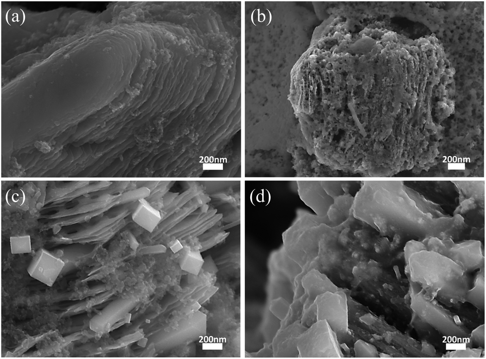
Fig. 1a shows the schematic illustration of the structure of the TiO2/Ti3C2Tx nanocomposite. There are a large number of metastable Ti ions present on both sides of Ti3C2Tx, which guarantees the building of the TiO2/Ti3C2Tx hybrid.12,26,27 By regulating the state of metastable Ti ions, the crystallinity of TiO2 can be rationally controlled. Fig. 1b is the SEM image of Ti3C2Tx, exhibiting a typical accordion-like layered structure. Fig. 1c shows the SEM image of the A-TiO2/Ti3C2Tx hybrid. Apparently, the accordion-like layered structure remains, while the surface of Ti3C2Tx is occupied by a large number of A-TiO2 nanoparticles. When introducing R-TiO2 into A-TiO2/Ti3C2Tx, as shown in Fig. 1d, regular octahedral nanocrystals have been observed which are deemed as R-TiO2. Fig. S1† shows the SEM images of A-TiO2 and A/R-TiO2, where the TiO2 particles agglomerate together. The elemental mapping image of A/R-TiO2/Ti3C2Tx in Fig. 1e clearly demonstrates the co-existence of Ti, C and O. Fig. 1f shows the high-resolution transmission electron microscope (HRTEM) image of A/R-TiO2/Ti3C2Tx with the enlarged HRTEM image of the selected area as well. The lattice fringes of d = 0.342 nm, 0.33 nm and 0.21 nm are associated with the (101) plane of A-TiO2, (110) plane of R-TiO2 and (105) plane of Ti3C2Tx, respectively, demonstrating the coexistence of A-TiO2, R-TiO2 and Ti3C2Tx-MXene.26,28 Consequently, the A/R-TiO2/Ti3C2Tx hybrid is successfully synthesized. | ||
| Fig. 1 (a) Schematic illustration of A/R-TiO2/Ti3C2Tx, the SEM images of (b) Ti3C2Tx, (c) A-TiO2/Ti3C2Tx, and (d) A/R-TiO2/Ti3C2Tx, (e) elemental mapping image of A/R-TiO2/Ti3C2Tx, and (f) HRTEM images of A/R-TiO2/Ti3C2Tx. | ||
Fig. 2a shows the X-ray diffraction (XRD) patterns of Ti3C2Tx, A-TiO2/Ti3C2Tx and A/R-TiO2/Ti3C2Tx. Basically, the characteristic peaks of Ti3C2Tx can be indexed in all samples, particularly two peaks at 9.08° and 18.22°.29 As a supplementary, the XRD patterns of A-TiO2 and A/R-TiO2 are given in Fig. S2.† In terms of the A-TiO2/Ti3C2Tx, except for the characteristic peaks of Ti3C2Tx, a new peak located at 25.31° has emerged, which corresponds to the (101) plane of A-TiO2. Upon the increase of the oxidation degree, a new peak appearing at 27.2° is assumed as the characteristic peak of the (110) plane of R-TiO2, proving the presence of the A/R-TiO2/Ti3C2Tx nanocomposite.25,30,31 By using quantitative full pattern Rietveld refinement from the XRD diffraction patterns of each phase, we have calculated the mass ratio of MXene in TiO2/MXene nanocomposites, which is 1:0.17 for MXene:A-TiO2 in the A-TiO2/Ti3C2Tx composite and 1:1.05:4.06 for MXene:A-TiO2:R-TiO2 in A/R-TiO2/Ti3C2Tx, respectively.
 | ||
| Fig. 2 (a) XRD patterns, (b) Raman spectra, (c) FTIR spectra, (d) O 1s spectra, (e) C 1s spectra, (f) Ti 2p spectra, (g) N2 adsorption–desorption isotherm, (h) pore size distribution and (i) EPR spectra of Ti3C2Tx, A-TiO2/Ti3C2Tx and A/R-TiO2/Ti3C2Tx. | ||
Fig. 2b and c presents the Raman and Fourier transform infrared spectroscopy (FTIR) spectra of all samples. In the Raman spectrum of Ti3C2Tx, a distinct peak between 140 cm−1 and 160 cm−1 refers to the typical C plane and the metastable Ti vibration modes. Besides, Ti–O vibration bands of surface groups arise at 202 cm−1.32,33 Compared with the Raman spectrum of pristine Ti3C2Tx, the appearance of strong Ti–O vibration peaks at 625 cm−1, 506 cm−1, 394 cm−1 and 150 cm−1 in the Raman spectrum of A-TiO2/Ti3C2Tx suggests the existence of A-TiO2 nanoparticles. Moreover, the shift of the peak from 394 to 385 cm−1 and decline of the peak at 150 cm−1 in the Raman spectrum of A/R-TiO2/Ti3C2Tx reveal the existence of R-TiO2 nanoparticles.34,35 In Fig. 2c, a broad band at 3100 cm−1 is ascribed to the stretching vibration of –OH groups that come from the terminations of Ti3C2Tx, which consist of –OH and –F terminations.36 The peaks at 1722 cm−1 and 2920 cm−1 are assigned to C![[double bond, length as m-dash]](https://www.rsc.org/images/entities/char_e001.gif) O and C–H stretching in pristine Ti3C2Tx, respectively, while bending of the –OH terminal groups of Ti3C2Tx contributes to absorption peaks at 1630 cm−1 and 584 cm−1. Assignments of the peaks at 1382 cm−1 and 1111 cm−1 are the C–F vibration and Ti–C–O vibration, respectively.37 Differing from the FTIR spectrum of Ti3C2Tx, a strong absorption band emerges from 500 cm−1 to 900 cm−1 in A-TiO2/Ti3C2Tx due to the existence of A-TiO2. Remarkably, in A/R-TiO2/Ti3C2Tx, the band at 840 cm−1 is attributed to the lattice stretching vibration of R-TiO2 (O–Ti–O). Beyond that, the peak at 650 cm−1 would be assigned to the (Ti–O) tensile zone, which is associated with A-TiO2.25,38 Based on the above results, we have successfully synthesized the MXene/TiO2 nanohybrids, in which the crystalinity of TiO2 can be precisely controlled by regulating the metastable Ti ions through a facile one-step method.
O and C–H stretching in pristine Ti3C2Tx, respectively, while bending of the –OH terminal groups of Ti3C2Tx contributes to absorption peaks at 1630 cm−1 and 584 cm−1. Assignments of the peaks at 1382 cm−1 and 1111 cm−1 are the C–F vibration and Ti–C–O vibration, respectively.37 Differing from the FTIR spectrum of Ti3C2Tx, a strong absorption band emerges from 500 cm−1 to 900 cm−1 in A-TiO2/Ti3C2Tx due to the existence of A-TiO2. Remarkably, in A/R-TiO2/Ti3C2Tx, the band at 840 cm−1 is attributed to the lattice stretching vibration of R-TiO2 (O–Ti–O). Beyond that, the peak at 650 cm−1 would be assigned to the (Ti–O) tensile zone, which is associated with A-TiO2.25,38 Based on the above results, we have successfully synthesized the MXene/TiO2 nanohybrids, in which the crystalinity of TiO2 can be precisely controlled by regulating the metastable Ti ions through a facile one-step method.
Fig. 2d shows the O 1s spectra of Ti3C2Tx, A-TiO2/Ti3C2Tx and A/R-TiO2/Ti3C2Tx. Apparently, the C–O bond doesn't have a violent change in all samples. In sharp contrast, the Ti–O bond is significantly enhanced in A/R-TiO2/Ti3C2Tx, suggesting the presence of a large amount of TiO2.14 Fig. 2e gives the C 1s spectra, which can be split into C–C, Ti–C and C–O bonds. The C–C and Ti–C bonds reveal the signature of the Ti–C–Ti structure in all samples. The attenuation of Ti–C peaks in A-TiO2/Ti3C2Tx and A/R-TiO2/Ti3C2Tx is indicative of oxidation of surface Ti ions into TiO2. In the Ti 2p spectrum (Fig. 2f), one pair of strong peaks located at 456.47 eV and 465.57 eV are correlated with the Ti2+, while two peaks centered at 455.27 eV and 461.27 eV indicate the existence of the Ti–C bond in Ti3C2Tx.14,15 There was a controversy; a new pair of peaks occur at about 458.57 and 464.27 eV, which are associated with the Ti–O bonds in A-TiO2/Ti3C2Tx and A/R-TiO2/Ti3C2Tx. In addition, the peak areal ratio of Ti–O/Ti–C (≈2.57) in A/R-TiO2/Ti3C2Tx is larger than that of A-TiO2/Ti3C2Tx (≈0.81), demonstrating the presence of a large amount of TiO2.8,9,15,32
Fig. 2g and h show the typical nitrogen adsorption–desorption isotherm and pore size distribution of Ti3C2Tx, A-TiO2/Ti3C2Tx and A/R-TiO2/Ti3C2Tx, respectively. The relatively apparent hysteresis loop is examined on the isotherms of the three samples, implying the mesoporous characteristic. Compared with pure Ti3C2Tx, the formation of the TiO2/Ti3C2Tx heterojunction structure would bring in larger mesopores, which contributes to larger specific surface area. Incorporation of TiO2 with different phases into MXene would further reinforce this effect, leading to increased specific surface area.39,40 Apparently, the N2 adsorption capacities of the samples follow the order of Ti3C2Tx < A-TiO2/Ti3C2Tx < A/R-TiO2/Ti3C2Tx. The formation of TiO2 nanocrystals on MXene provides more adsorption sites for Na ions. Furthermore, we made BET measurements on the three samples, which show that the specific surface area (SSA) of Ti3C2Tx, A-TiO2/Ti3C2Tx and A/R-TiO2/Ti3C2Tx is 5.0, 6.0 and 22.5 m2 g−1, respectively. In strong contrast to Ti3C2Tx and A-TiO2/Ti3C2Tx, the dominant pore size of A/R-TiO2/Ti3C2Tx concentrates on 3–5 nm. The improved SSA with rational pore size makes A/R-TiO2/Ti3C2Tx possess more sodium ion storage sites, which could adapt to strain/stress during cycling and promote electrode/electrolyte contact.41,42
Fig. 2i shows the electron paramagnetic resonance (EPR) spectra of Ti3C2Tx, A-TiO2/Ti3C2Tx and A/R-TiO2/Ti3C2Tx. The signal response at 3515 gauss has been observed in all samples, corresponding to a g factor of 2.003, which is a characteristic of oxygen vacancies24 In Ti3C2Tx, the oxygen vacancies may be related to the surface functional groups. After oxidation, the oxygen vacancies of A-TiO2/Ti3C2Tx have significantly increased, and the signal intensity is about 4.34 times higher than that of Ti3C2Tx. Additionally, the signal factor of A/R-TiO2/Ti3C2Tx is the strongest among all samples, with ∼7.38 times higher signal intensity of Ti3C2Tx. Notably, oxygen vacancies have been demonstrated to improve the electronic structure, charge transfer, and surface properties of TiO2 by narrowing the band gap, resulting in the accelerated Na+ adsorption and diffusion kinetics.43–45
3.2 Electrochemical performance and ion diffusion kinetics
The cycling performances of the Ti3C2Tx, A-TiO2/Ti3C2Tx and A/R-TiO2/Ti3C2Tx electrodes at 100 mA g−1 are exhibited in Fig. 3a. The three electrodes realize good cycling stability. Remarkably, the A/R-TiO2/Ti3C2Tx electrode delivers a reversible capacity of 183.5 mA h g−1 after 100 cycles, while the reversible capacities of Ti3C2Tx and A-TiO2/Ti3C2Tx separately are only 96.8 and 107.9 mA h g−1. As a comparison, Fig. S3† shows the reversible capacities of A-TiO2 and A/R-TiO2 after 100 cycles, which are 55.6 and 118.7 mA h g−1, respectively. Both are far less than the capacity of the A/R-TiO2/Ti3C2Tx anode. Further, Fig. 3b shows that the rate capacities of the A/R-TiO2/Ti3C2Tx electrode are 205.4, 135.7, 103.5, 77.5 and 40.6 mA h g−1 at 100, 500, 1000, 2000 and 5000 mA g−1. These values are considerably higher than those for the A-TiO2/Ti3C2Tx and Ti3C2Tx electrodes, which are 132.4 mA h g−1, 78.3 mA h g−1, 50.1 mA h g−1, 25.6 mA h g−1, and 11.4 mA h g−1 and 109.9 mA h g−1, 59.7 mA h g−1, 31.1 mA h g−1, 11.4 mA h g−1, and 12.6 mA h g−1, respectively. Fig. 3c displays the first four continued CV curves of the A/R-TiO2/Ti3C2Tx with potential windows of 0.01–3.0 V at 0.1 mV s−1. As illustrated, the irreversible oxidation peak in the anodic process for the first cycle can be ascribed to the decomposition of the electrolyte, the formation of the solid electrolyte interface (SEI), or the irreversible muti-electrochemical reactions.46 In the case of the first sodiation process, two broad anodic peaks occurred at 1.39 V and 2.03 V, respectively, and their intensity decreased compared with the subsequent cycles, corresponding to the extraction of sodium ions from the Ti3C2Tx electrode. No significant shift was observed in subsequent cycles, suggesting that the charge storage in Ti3C2Tx was due to the intercalation of Na+ rather than a conversion reaction.12,14 In the following three subsequent cycles, a cathodic peak near 2.35 V can be clearly observed due to the sodiation, while an anodic peak near 0.45 V is attributed to the de-sodiation. This reversible process is accompanied by the conversion of Ti4+/Ti3+ couples in the A/R-TiO2/Ti3C2Tx.14,17,46 Beyond the first cycle, the subsequent cycles are almost overlapping, implying the high reversibility of the electrode. The selected charge–discharge curves of A/R-TiO2/Ti3C2Tx within 0–3.0 V at a current density of 100 mA g−1 are drawn in Fig. 3d. The initial discharge and charge capacity were 774.7 and 270.9 mA h g−1, respectively, delivering a Coulomb efficiency (CE) of 35%. The low CE and huge irreversible capacity loss are mainly resulted from the formation of SEI film and irreversible electrochemical reaction.16,47 Interestingly, the charge–discharge curves after the first cycles are going to overlap, suggesting the improved reversibility of the A/R-TiO2/Ti3C2Tx electrode. Fig. 3e illustrates the long cycling performance of A/R-TiO2/Ti3C2Tx at 500 mA g−1 in 600 cycles. Essentially, the reversible initial and final capacities are 128.8 and 109.1 mA h g−1, respectively, deducing a capacitance retention rate of 84.7%. | ||
| Fig. 3 (a) Cycling performances at 100 mA g−1 and (b) rate capabilities of Ti3C2Tx, A-TiO2/Ti3C2Tx and A/R-TiO2/Ti3C2Tx, (c) CV curve of A/R-TiO2/Ti3C2Tx, (d) GCD curves at 100 mA g−1 and (e) cycling performances at 500 mA g−1, (f) CV curves of A/R-TiO2/Ti3C2Tx at scan rates ranging from 0.1 to 2.0 mV s−1, and (g) and (h) the capacitive contribution of A/R-TiO2/Ti3C2Tx at 0.1 mV s−1, normalized contribution ratios of capacitive and diffusion-controlled capacity of A/R-TiO2/Ti3C2Tx at different scan rates. | ||
To figure out the charge-storage mechanism of the A/R-TiO2/Ti3C2Tx electrode, cyclic voltammetry (CV) profiles at various scan rates were tested. Fig. 3e illustrates the CV curves of A/R-TiO2/Ti3C2Tx at scan rates of 0.1, 0.3, 0.5, 0.7, 1.0 and 2.0 mV s−1, respectively. Classically, the charge-storage mechanism can be investigated by exploring the relationship between the peak current (i, mA) and the scan rates (ν, mV s−1):
| i = avb | (1) |
|
log(i) = blog(v) + log(a)
| (2) |
| i(v) = k1v + k2v1/2 | (3) |
| i(v)/v1/2 = k1v1/2 + k2 | (4) |
Fig. 4a shows the Nyquist plot and equivalent circuit diagrams of the three electrodes at a frequency of 0.01 to 106 Hz. As shown in Fig. 4a, all plots exhibit similar shapes composed of a straight line in the low frequency area and a semicircle in the high frequency range.49 The equivalent circuit is given in the inset, where Rs, Rct and W0 represent the electrolyte resistance, the interfacial charge transfer resistance and the Warburg impedance related to the Na+ diffusion within the electrode.50 As shown in Table 1, Rct significantly decreases when TiO2 is incorporated in Ti3C2Tx regardless of the crystal type. This can be attributed to the improved conductivity and increased electroactive sites. Moreover, the Rct of A/R-TiO2/Ti3C2Tx is 42.46 Ω, which is much lower than that of A-TiO2/Ti3C2Tx (119 Ω), indicating the high interfacial charge transfer which is beneficial to enhance the rate capability. Except for the resistance, we calculated the diffusion coefficient of sodium ions (DNa+) from the low frequency domain, which can be expressed by the following equations:
 | (5) |
| Z′ = Re + Rct + σω1/2 | (6) |
 | ||
| Fig. 4 (a) EIS spectra and Nyquist plots, and (b) relationship between Z′ and ω−1/2 at low frequencies. | ||
| Electrode | Rct/Ω | σ/ohm cm2 s−0.5 | DNa+/cm2 s−1 |
|---|---|---|---|
| Ti3C2Tx | 289.8 | 57 | 2.858 × 10⁻¹⁵ |
| A-TiO2/Ti3C2Tx | 119 | 55.1 | 8.602 × 10⁻¹⁵ |
| A/R-TiO2/Ti3C2Tx | 42.46 | 48 | 4.01 × 10⁻¹⁴ |
R denotes the molar gas constant (8.314 J K−1 mol−1), T is the absolute temperature (298.15 K), A is the area of the electrode, n is the number of electrons transferred during the reaction, C is the sodium ion concentration and F is the Faraday constant (96486 C mol−1). Fig. 4b shows the relationship between Z′ and ω−1/2 at low frequencies.32 The values of σ and the DNa+ are summarized in Table 1. The DNa+ of A/R-TiO2/Ti3C2Tx is 4.01 × 10⁻¹⁴ cm2 s−1 which is approximately 14.01 times and 4.66 times higher than the DNa+ of Ti3C2Tx (2.858 × 10−15 cm2 s−1) and A-TiO2/Ti3C2Tx (8.602 × 10−15 cm2 s−1), respectively. This is presumably ascribed to the incorporation of long rod-like R-TiO2 nanocrystals, which can effectively relieve the collapse of Ti3C2Tx layers.
Fig. 5a and b show the SEM images of the Ti3C2Tx electrode before and after the cycling, respectively. Obviously, the layered structure of pure Ti3C2Tx seriously collapsed after cycling. In sharp contrast, the structure of A/R-TiO2/Ti3C2Tx remains largely unaffected (Fig. 5c and d), illustrating its desirable stability.
 | ||
| Fig. 5 SEM images of (a and b) the pure Ti3C2Tx and (c and d) A/R-TiO2/Ti3C2Tx electrode before/after 100 charging–discharging cycles, respectively. | ||
4. Conclusions
Through the surface regulation of Ti3C2Tx, we generated A-TiO2 and R-TiO2 in situ from metastable Ti ions on the surface of Ti3C2Tx by a one-step method to obtain nano hybrid structures. The growth of crystalline A-TiO2 and R-TiO2 is beneficial to improve the collapse of Ti3C2Tx. The 2D structure can provide a fast channel for the transmission of Na+. A-TiO2 and R-TiO2 crystals can introduce more active sites for Na+. Moreover, the crystals can provide a supporting effect for the layered structure and maintain the integrity and firmness of the structure. Meanwhile, a large number of oxygen vacancies can be introduced into the composite which are conducive to the insertion and extraction of Na+. Due to the advantages of the A/R-TiO2/Ti3C2Tx hybrid structure, the prepared A/R-TiO2/Ti3C2Tx electrode has proved high capacity, great rate performance and long-term cycle stability. We believe that these findings will provide new ideas for the design of nanostructured electrodes for advanced rechargeable batteries.Conflicts of interest
There are no conflicts to declare.Acknowledgements
This work was supported by the National Natural Science Foundations of China (NSFC11704207) and project of Ningxia key R&D plan (2021BEE03006).References
- K. Chayambuka, G. Mulder, D. L. Danilov and P. H. L. Notten, Adv. Energy Mater., 2020, 10, 2001310 CrossRef CAS.
- Y. R. Lim, F. Shojaei, K. Park, C. S. Jung, J. Park, W. I. Cho and H. S. Kang, Nanoscale, 2018, 10, 7047–7057 RSC.
- L. Sun, J. Xie, X. Zhang, L. Zhang, J. Wu, R. Shao, R. Jiang and Z. Jin, Nanoscale, 2020, 49, 15712–15717 CAS.
- F. Yang, F. Yu, Z. Zhang, K. Zhang, Y. Lai and J. Li, Chem.–Eur. J., 2016, 22, 2333–2338 CrossRef CAS PubMed.
- J. Zhu, J. Roscow, S. Chandrasekaran, L. Deng, P. Zhang, T. He, K. Wang and L. Huang, ChemSusChem, 2020, 13, 1275–1295 CrossRef CAS PubMed.
- K.-H. Nam, K.-J. Jeon and C.-M. Park, Energy Storage Mater., 2019, 17, 78–87 CrossRef.
- Y. Zhang, N. Wang and Z. Bai, Appl. Sci., 2020, 10, 3098 CrossRef CAS.
- J. Lee, J. K. Lee, K. Y. Chung, H.-G. Jung, H. Kim, J. Mun and W. Choi, Electrochim. Acta, 2016, 200, 21–28 CrossRef CAS.
- P. Ma, D. Fang, Y. Liu, Y. Shang, Y. Shi and H. Y. Yang, Adv. Sci., 2021, 8, 2003185 CrossRef CAS PubMed.
- J. Li, C. Guo and C. M. Li, ChemSusChem, 2020, 13, 1047–1070 CrossRef CAS PubMed.
- A. VahidMohammadi, W. Liang, M. Mojtabavi and M. Wanunu, Energy Storage Mater., 2021, 41, 554–562 CrossRef.
- G. Lv, J. Wang, Z. Shi and L. Fan, Mater. Lett., 2018, 219, 45–50 CrossRef CAS.
- B. Sun, Q. Lu, K. Chen, W. Zheng, Z. Liao, N. Lopatik, D. Li, M. Hantusch, S. Zhou, H. I. Wang, Z. Sofer, E. Brunner, E. Zschech, M. Bonn, R. Dronskowski, D. Mikhailova, Q. Liu, D. Zhang, M. Yu and X. Feng, Adv. Mater., 2022, e2108682, 1–11 Search PubMed.
- P. Wang, X. Lu, Y. Boyjoo, X. Wei, Y. Zhang, D. Guo, S. Sun and J. Liu, J. Power Sources, 2020, 451, 227756 CrossRef CAS.
- Z. Yuan, Y. Fan, Y. Chen, X. Liu, B. Liu and S. Han, Int. J. Hydrogen Energy, 2020, 45, 21666–21675 CrossRef CAS.
- L. Wang, X. Zhang, Y. Xu, C. Li, W. Liu, S. Yi, K. Wang, X. Sun, Z. S. Wu and Y. Ma, Adv. Funct. Mater., 2021, 31, 2104286 CrossRef CAS.
- C. Yang, Y. Liu, X. Sun, Y. Zhang, L. Hou, Q. Zhang and C. Yuan, Electrochim. Acta, 2018, 271, 165–172 CrossRef CAS.
- Y. Zhang, X. Pu, Y. Yang, Y. Zhu, H. Hou, M. Jing, X. Yang, J. Chen and X. Ji, Phys. Chem. Chem. Phys., 2015, 17, 15764–15770 RSC.
- H. Usui, Y. Domi, T. H. Nguyen, Y. Tanaka and H. Sakaguchi, ACS Omega, 2020, 5, 15495–15501 CrossRef CAS PubMed.
- Z. Hong, K. Zhou, J. Zhang, Z. Huang and M. Wei, J. Mater. Chem. A, 2015, 3, 17412–17416 RSC.
- G. Zou, J. Chen, Y. Zhang, C. Wang, Z. Huang, S. Li, H. Liao, J. Wang and X. Ji, J. Power Sources, 2016, 325, 25–34 CrossRef CAS.
- E. Ventosa, B. Mei, W. Xia, M. Muhler and W. Schuhmann, ChemSusChem, 2013, 6, 1312–1315 CrossRef CAS PubMed.
- E. Ventosa, A. Tymoczko, K. Xie, W. Xia, M. Muhler and W. Schuhmann, ChemSusChem, 2014, 7, 2584–2589 CrossRef CAS PubMed.
- H. He, D. Sun, Q. Zhang, F. Fu, Y. Tang, J. Guo, M. Shao and H. Wang, ACS Appl. Mater. Interfaces, 2017, 9, 6093–6103 CrossRef CAS PubMed.
- H. He, D. Huang, W. Pang, D. Sun, Q. Wang, Y. Tang, X. Ji, Z. Guo and H. Wang, Adv. Mater., 2018, 30, 1801013 CrossRef PubMed.
- A. A. Khan and M. Tahir, Appl. Catal., B, 2021, 285, 119777 CrossRef CAS.
- S. Elumalai, M. Yoshimura and M. Ogawa, Chem.–Asian J., 2020, 15, 1044–1051 CrossRef CAS PubMed.
- Y. Fang, B. Tan, Q. Chen, X. Ao and Y. Cao, J. Colloid Interface Sci., 2021, 601, 581–593 CrossRef PubMed.
- T. Huang, Y. Jiang, G. Shen and D. Chen, ChemSusChem, 2020, 13, 1093–1113 CrossRef CAS PubMed.
- N. Radić, B. Grbić, S. Petrović, S. Stojadinović, N. Tadić and P. Stefanov, Phys. B, 2020, 599, 412544 CrossRef.
- L. N. Quan, Y. H. Jang, Y. J. Jang, J. Kim, W. Lee, J. H. Moon and D. H. Kim, ChemSusChem, 2014, 7, 2590–2596 CrossRef CAS PubMed.
- H. Zhang, L. Yang, P. Zhang, C. Lu, D. Sha, B. Yan, W. He, M. Zhou, W. Zhang, L. Pan and Z. Sun, Adv. Mater., 2021, 33, 2008447 CrossRef CAS PubMed.
- T. Hu, J. Wang, H. Zhang, Z. Li, M. Hu and X. Wang, Phys. Chem. Chem. Phys., 2015, 17, 9997–10003 RSC.
- S. A. Bhandarkar, Prathvi, A. Kompa, M. S. Murari, D. Kekuda and R. K. Mohan, Opt. Mater., 2021, 118, 111254 CrossRef CAS.
- Prathvi, S. A. Bhandarkar, A. Kompa, D. Kekuda, M. M. S. Murari, M. P. Telenkov, K. K. Nagaraja and K. Mohan Rao, Surf. Interfaces, 2021, 23, 100910 CrossRef CAS.
- M. Naguib, M. Kurtoglu, V. Presser, J. Lu, J. Niu, M. Heon, L. Hultman, Y. Gogotsi and M. W. Barsoum, Adv. Mater., 2011, 23, 4248–4253 CrossRef CAS PubMed.
- Z. Shen, W. Chen, H. Xu, W. Yang, Q. Kong, A. Wang, M. Ding and J. Shang, Int. Res. J. Publ. Environ. Health, 2019, 16, 4659 CrossRef CAS PubMed.
- N. Malesic Eleftheriadou, A. Ofrydopoulou, M. Papageorgiou and D. Lambropoulou, Appl. Sci., 2020, 10, 2368 CrossRef.
- P. Gao, H. Shi, T. Ma, S. Liang, Y. Xia, Z. Xu, S. Wang, C. Min and L. Liu, ACS Appl. Mater. Interfaces, 2021, 13, 51028–51038 CrossRef CAS PubMed.
- L. Wang, J. Ren, Q. Gong, J. Xuan, M. Sun, H. Zhang, Q. Zhang, G. Yin and B. Liu, J. Mater. Sci., 2022, 57, 5396–5409 CrossRef CAS.
- R. B. Ambade, G. K. Veerasubramani, S. B. Ambade, M. Christy, W. Eom, H. Shin, Y.-B. Kim, D.-W. Kim and T. H. Han, Carbon, 2021, 178, 332–344 CrossRef CAS.
- Z. Sun, Z. Zhang and H. Li, Mater. Lett., 2021, 303, 130570 CrossRef CAS.
- Y. Zhang, Z. Ding, C. W. Foster, C. E. Banks, X. Qiu and X. Ji, Adv. Funct. Mater., 2017, 27, 1700856 CrossRef.
- L. Huang, L. Zeng, J. Zhu, L. Sun, L. Yao, L. Deng and P. Zhang, J. Power Sources, 2021, 493, 229678 CrossRef CAS.
- Q. Wang, S. Zhang, H. He, C. Xie, Y. Tang, C. He, M. Shao and H. Wang, Chem.–Asian J., 2021, 16, 3–19 CrossRef CAS PubMed.
- Y. Li, C. Chen, M. Wang, W. Li, Y. Wang, L. Jiao and H. Yuan, J. Power Sources, 2017, 361, 326–333 CrossRef CAS.
- Z. Zhang, Y. Du and H. Li, Nanotechnology, 2020, 31, 095402 CrossRef CAS PubMed.
- X. Zhao, W. Wang, Z. Hou, X. Fan, G. Wei, Y. Yu, Q. Di, Y. Liu, Z. Quan and J. Zhang, Inorg. Chem. Front., 2019, 6, 562–565 RSC.
- G. Ma, H. Shao, J. Xu, Y. Liu, Q. Huang, P. L. Taberna, P. Simon and Z. Lin, Nat. Commun., 2021, 12, 5085 CrossRef CAS.
- A. Henry, N. Louvain, O. Fontaine, L. Stievano, L. Monconduit and B. Boury, ChemSusChem, 2016, 9, 264–273 CrossRef CAS.
Footnote |
| † Electronic supplementary information (ESI) available: The experimental details, XRD patterns, SEM images and cycling performances of A-TiO2 and R-TiO2. See https://doi.org/10.1039/d2ra01589g |
| This journal is © The Royal Society of Chemistry 2022 |