
 Open Access Article
 This Open Access Article is licensed under a Creative Commons Attribution-Non Commercial 3.0 Unported Licence
Misorientations across boundary planes in a sintered NdFeB permanent magnet
Xiaokun Yuan *a and
Jie Zhub
*a and
Jie Zhub
aFaculty of Materials and Manufacturing, Beijing University of Technology, Beijing 100124, China. E-mail: yuanxiaokun@bjut.edu.cn; Fax: +86 10 67396563; Tel: +86 10 67396563
bState Key Laboratory for Advanced Metals and Materials, University of Science and Technology Beijing, Beijing 100083, China
First published on 13th July 2022
Abstract
From the perspective of crystallography, there exist crystals as well as boundary planes in NdFeB permanent magnets and accordingly, there should exist orientation textures of Nd2Fe14B crystals and orientation texture of boundary planes. This work therefore aims to study the misorientations across boundary planes in a sintered NdFeB permanent magnet. As an interdisciplinary study, serial stereological methods are developed to extract more structural information from the material and as the result, spreading wetting and penetration of Nd-Rich phases to the Nd2Fe14B phase are quantificationally characterized. The entire boundaries are sorted into Nd2Fe14B/Nd2Fe14B grain boundaries (N/N boundaries) and Nd2Fe14B/(thin-layer-like)Nd-Rich phase boundaries (N/R boundaries). 31°/[0 0 1] and 60°/[0 0 1] twist boundaries are preferred among N/N boundaries, while 31°/[0 0 1] and 72°/[0 0 1] misorientations are preferred among N/R boundaries. The structural features of these misorientations are elaborated via the Five Parameter Analysis (FPA) method. The potential correlations between the grain boundary plane distributions (GBPDs) and magnetic properties are then discussed regarding how the anisotropic features at boundary locations impact coercivity, domain and remanence.
1. Introduction
Following the discovery of NdFeB permanent magnets in 1984,1,2 research efforts have increased the understanding of the main intrinsic magnetic properties of the Nd2Fe14B phase (chemical name: neodymium iron boride, space group: P4_2/mnm) including coercivity, remanence and magnetic domain mechanisms.3 From the perspective of polycrystalline structure, a NdFeB permanent magnet is composed of a Nd2Fe14B main phase and various Nd-Rich phases. The Nd-Rich phases can either distribute as thin layer between Nd2Fe14B crystals (such case is preferred since it can act as “shells” and thus uniformly isolate the Nd2Fe14B crystals) or distribute as “Nd-Rich corners” at triple junctions of Nd2Fe14B crystals (such case is not preferred since it contribute poorly to the magnetic properties). Accordingly, to comprehensively study the structure–property relationship in a NdFeB permanent magnet, two kinds of boundary planes needs to be focused: the one is grain boundaries between Nd2Fe14B crystals (abbreviated as Nd2Fe14B/Nd2Fe14B grain boundaries, or, N/N boundaries, in this work), and the other is phase boundaries between Nd2Fe14B crystals and thin-layer-like Nd-Rich phases (abbreviated as Nd2Fe14B/Nd-Rich phase boundaries, or, N/R boundaries, in this work).From the perspective of methodology, corresponding to Nd2Fe14B crystals and various boundary planes, there should have orientation texture of Nd2Fe14B crystals and orientation texture of boundary planes.4 Electron backscatter diffraction (EBSD) is the basic technique that transfers the collected Kikuchi patterns to the crystal orientation information via the Hough conversion. For NdFeB permanent magnets, the axial [001] texture of Nd2Fe14B crystals is commonly used to show the alignment of 〈001〉 crystal directions with reference to the sample normal in a statistical meaning. However, compared to abundant studies about orientation texture of Nd2Fe14B crystals, reports about orientation texture of boundary planes in NdFeB permanent magnets remains limited. Nevertheless, methodology to study the orientation texture of boundary planes, namely “Five Parameter Analysis (FPA)” method5,6 has been widely used to study the grain boundary plane distribution (GBPD) in multiple polycrystalline materials. To emphasize, FPA on a single planar section merely suitable for bulk with weak orientation texture of crystals, while FPA on consecutive planar sections (3D-EBSD) is also suitable for bulk with strong orientation texture of crystals (like the case in most NdFeB permanent magnets).
As the interdisciplinary between polycrystalline structure and stereological methods, the current work studies the orientation texture of boundary planes in NdFeB permanent magnets under the following motivations: (1) the lattice order at boundary plane locations is generally lower than that in the crystal interior. This reminds us to study the GBPD of both N/N boundaries and N/R boundaries, and further study the potential correlation between the GBPD with the anisotropic magnetic properties. (2) The boundary planes occupy a considerable volume fraction in NdFeB permanent magnets. The smaller the Nd2Fe14B crystal size, the larger the volume of the boundary plane.7 This reminds us to check the impact of higher volume fraction of boundary planes, or, thicker boundary layers, to the magnetic properties. (3) Specific method has been developed to sort N/N boundaries and N/R boundaries6 (compared with ref. 6, the major difference in current work is that both N/N boundaries and N/R boundaries are studied), which is helpful to seek more beneficial clues for improving magnetic properties via optimizing of GBPD. (4) New routines are emerging for fabricating NdFeB permanent magnets. Therefore, it should be clarified that whether the stereology method is suitable for various NdFeB structures, and in-turn, whether results in academic laboratories can be applied to practices in industrial laboratories.
2. Experimental
Most of NdFeB permanent magnets have strong orientation texture of Nd2Fe14B crystals, and GBPD in such cases can merely be measured via 3D-EBSD. Since the main prospect of this work is developing practical stereological methods for characterizing the microstructure of NdFeB permanent magnets, a specimen with a weak orientation texture of Nd2Fe14B crystals is chosen and regular EBSD measurements on a single planar section is performed.To fabricate such a specimen, commercial jet-milled powders with the nominal particle size of 5 μm were used as the starting materials. The powders were mixed with a 2.5 wt% epoxy and then were aligned and pressed in a 1.0 T magnetic field to obtain the green compact. Next, the green compact was isostatically consolidated by using a spark plasma sintering (SPS) equipment, with a temperature of 1050 °C for 5 h, followed by a two-step annealing treatment. The features of the selected specimen are: (1) Nd2Fe14B crystals have a smaller average size; (2) Nd2Fe14B crystals have a relative weak orientation texture and (3) the thin layer of Nd-Rich phases has a average thickness larger than 0.1 micron. These features can ensure the spatial accuracy of EBSD data and can facilitate the boundary sorting step.
The phase components of the specimen were investigated by an X-ray diffractometer (XRD, Rigaku Ultima IV) with Cu Kα as the incident radiation. The magnetic properties of the specimen were tested by a hysteresis loop tracer, and a commercial sample (which is named as N48 and has a strong orientation texture of Nd2Fe14B crystals) is also tested for comparison. Then, the specimen underwent a mechanical polishing procedure to produce suitable surface for EBSD measurement. The EBSD measurement was preformed by an EDAX Hikari camera incorporated into JEOL-6500F scanning electron microscope (SEM) with a step size of 0.05 micron. During EBSD measurement, only the phase file of Nd2Fe14B is loaded. As the result, on the crystal orientation map, only Nd2Fe14B crystals are identified and the Nd-Rich phases are shown as black regions. The EBSD data then underwent a clean-up procedure and then exported reconstructed boundary files for further analysis.
Before the stereological analysis, the whole boundaries in the collected EBSD data are sorted into different subsets: if the phases on the two sides of a boundary trace are both Nd2Fe14B phases, that boundary is a N/N boundary; if merely one phase on the two sides of a boundary trace can be identified as Nd2Fe14B phase, that boundary is a N/R boundary. To emphasize, Nd-Rich phases contain complicated components (they might have fcc, dhcp and other symmetries and even can be amorphous under specific conditions), therefore, when and only when study GBCD this work, the Nd-Rich phases are simplified as one suppositional phase that has the same tetragonal symmetry of Nd2Fe14B main phase. Although this assumption is not exactly appropriate and may lead to errors that correlated to symmetries, it presents an intuitional way to study the lattice feature of N/R boundaries at the present stage.
Next, stereological analysis to N/N boundaries and N/R boundaries are performed. Detailed stereological statistics of the two subsets include number fraction, length fraction, number density (number of that boundary type per square micron), length density (length of that boundary type per square micron), average length (total length divided by total number of that boundary type) and triple junction density (number of a certain triple junction type per square micron), respectively.
And next, FPA analysis is performed on both N/N boundaries and N/R boundaries. For the two subsets, the misorientation angles across the boundary plane are counted, and by comparing with the random distribution,8 the preferred misorientation angles in each subset are observed. The observations needed for FPA analysis are line segments that are extracted from the EBSD measurement data and are associated with the crystal orientations. The FPA method does not determine the detailed crystallographic information for a specific boundary, but presents statistical information of GBCD. Using FPA method, the GBPD, λ(Δg, n), is defined as the relative area of a boundary plane with a misorientation, Δg, and a plane normal, n, in units of multiples of a random distribution (abbreviated as MRD).5 Therefore, FPA has two calculation modes: λ(Δg, n) represents the orientation texture of boundary planes with specific misorientation, and λ(n) represents the orientation texture of habit planes when misorientations are ignored. For the tetragonal symmetry, 45 × 104 line segments are needed for λ(Δg, n) mode, and 1 × 10⁴ line segments are needed for λ(n) mode. For the preferred misorientations in N/N boundaries, λ(Δg, n) analysis is given, and the geometrically characteristic locations of the studied misorientations were calculated via a crystallographic program named as GBToolbox,9 which would define the boundary structure as twist, tilt, 180°-twist (symmetric) or 180°-tilt (improperly quasi-symmetric).10 For N/N boundaries, N/R boundaries and the preferred misorientations in N/N boundaries, λ(n) analysis is given, respectively.
3. Results
The microstructure of a selected measurement region is shown by the inverse pole figure (IPF) map in Fig. 1a, with crystallographic orientations indicated by the orientation legend for tetragonal symmetry. A relative weak orientation texture of Nd2Fe14B crystals can be observed, and the Ni-Rich phases between Nd2Fe14B crystals are identified as black regions. Several regions were measured and the EBSD data were combined to meet the statistical requirement of FPA method. To accent, the Hikari camera does scanned the whole measurement region. Since only the phase file of Nd2Fe14B is loaded, the Nd2Fe14B crystals can be identified and the colors corresponding to their orientations can be assigned in Fig. 1a. On the contrary, since the in-tact Nd-rich phases have completely different crystal structures compared with Nd2Fe14B, the Nd-rich phases crystals can not be identified during scanning and no color can be assigned, in-turn, Nd-rich phases would be shown as black pixels in Fig. 1a. As the consequence, the N/R boundaries exist between colored pixels and black pixels in Fig. 1a.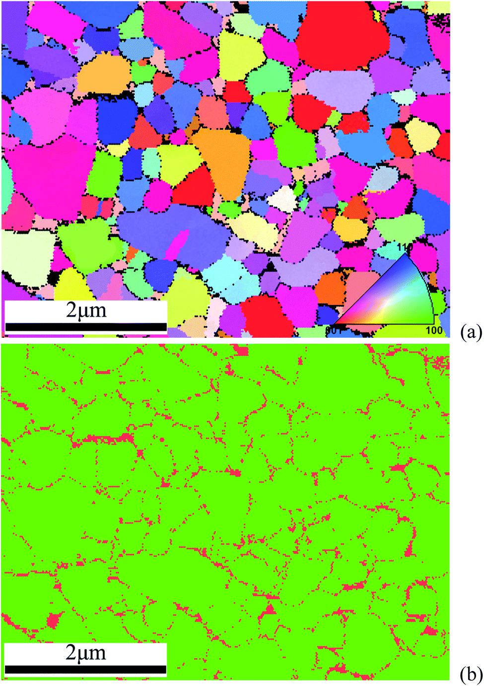 | ||
| Fig. 1 The microstructure of a selected measurement region: (a) inverse pole figure (IPF) map of a selected measurement region. Nd2Fe14B crystals are identified as colorized regions, with crystallographic orientations indicated by the orientation legend for tetragonal symmetry. Nd-Rich phases are shown as black regions between Nd2Fe14B crystals. (b) Phase map showing the spatial distribution of Nd2Fe14B phase (in green) and Nd-Rich phase (in red). | ||
A SEM image (preferably the backscatter electron, BSE, image) would be helpful to illustrate the microstructure, but it is not presented in this work due to the following reasons: (1) the electron beam scatters more at greater depths, which would results in poorer resolution compared with that of the secondary electron (SE) image as well as EBSD map; (2) both Nd2Fe14B phase and Nd-Rich phases contains Nd atoms, which would lead to the difficulty in distinguishing the phases planarly in the measurement region.11 As the alternative, the phase distribution of the same measurement region is shown by the phase map in Fig. 1b, in which green is for Nd2Fe14B phase while red is for Nd-Rich phases. By comparing with Fig. 1a and b can (1) directly show the spatial distribution feature of Nd2Fe14B phase and Nd-Rich phases, that is, the Nd-Rich phases scatter along the Nd2Fe14B crystals, which in-turn locate the distribution of both crystals and boundaries; (2) further show that the manually-processed black pixels in Fig. 1a corresponds to the in-tact Nd-Rich phases and do not mean the absence of orientation assignment.
The XRD measurement result of the specimen is shown in Fig. 2. Three strongest diffraction peaks can be indexed to the standard patterns of Nd2Fe14B phase (JCPDS 39-0473), and the rest strong peaks might correspond to Nd-Rich phases. The result clearly shows the coexistence of Nd2Fe14B phase and Nd-Rich phases.
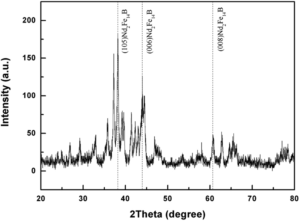 | ||
| Fig. 2 The XRD measurement of the sample, with grid lines indicating the top three strongest peak positions of Nd2Fe14B phase. | ||
The magnetic properties are illustrated by the magnetization hysteresis loop that were measured at room temperature and are shown in Fig. 3. The specimen has relative weak properties, including a remanence (Br) of 8.02 kG and a coercivity (Hc) of 11.16 kOe. By comparing with the properties of N48 (a remanence of 14.87 kG, a coercivity of 12.98 kOe and thus a square-loop configuration), it can be conceived that high Br can be achieved if the microscopically anisotropic crystals are aligned with their easy axes pointing in the same direction. Moreover, the specimen has a remanence that is approximately half the saturation magnetisation for Nd2Fe14B at room temperature, which means that the material is more isotropic, in other words, orientation textures of Nd2Fe14B crystals is relatively weak, despite the application of a magnetic field during processing. However, the orderliness of the boundary planes between these crystals, that is, orientation texture of boundary planes, still needs to be clarified. As the consequence, the structure–property relationship can be more comprehensive if the orientation texture contents can be surveyed more completely.
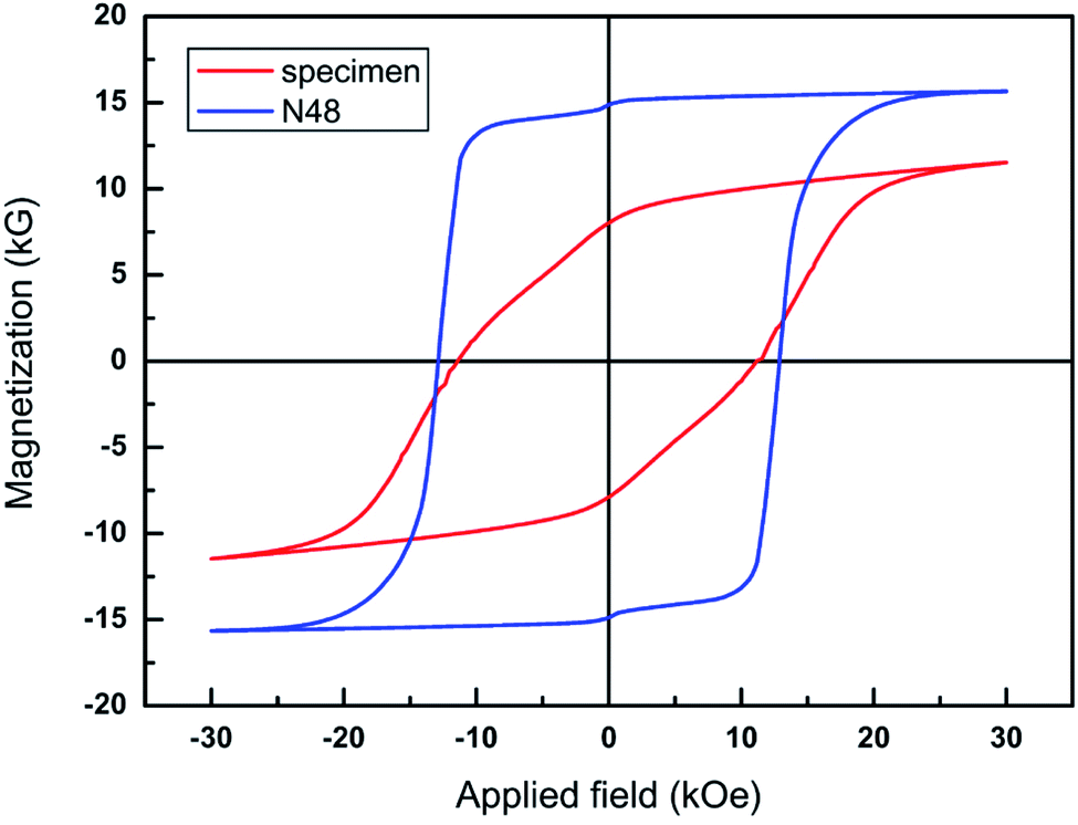 | ||
| Fig. 3 Magnetization hysteresis loops of the specimen in this work (red) and the N48 commercial sample (blue) measured at room temperature. | ||
The results of serial stereological analysis to N/N boundaries and N/R boundaries are summarized in Table 1, which reveals new structural information from the measured planar EBSD data. By virtue of number fraction, length fraction, number density and length density, the spatial distribution features of N/N boundaries and N/R boundaries can be quantified and thus, the four indexes can be used as the proxy to elaborate the boundary components in NdFeB permanent magnets. The average length is a novel and significant index: for N/N boundaries, longer average length corresponds to tighter contacting between Nd2Fe14B crystals; while for N/R boundaries, longer average length corresponds to better spreading wetting of Nd-Rich phases on the surface of Nd2Fe14B crystals. The triple junction density is calculated after the number of triple junctions in the “Nd-Rich corners” is subtracted from the number of triple junctions in the whole boundaries; therefore, the calculated triple junctions in N/R subsets should correspond to either the Nd2Fe14B/Nd-Rich/Nd2Fe14B (abbreviated as N/R/N) or the Nd-Rich/Nd2Fe14B/Nd-Rich (abbreviated as R/N/R) triple boundaries. Consequently, the calculated triple junction density represents the infiltration effect of Nd-Rich phases to Nd2Fe14B phase. As to the veracity of Table 1, it can be seen from Fig. 1b that the individual pixels of the Nd-Rich phases have been included in the statistics in Table 1. The average length of both N/N and N/R boundaries is about 0.1 μm while the step size of Fig. 1a is 0.05 μm, therefore, the average length of N/N and N/R boundaries is about 2 pixels. N/N boundaries occupy 83% boundary populations in Table 1, which means a not-very satisfied enwrapping of Nd-Rich phases to Nd2Fe14B phase. On the other hand, the 11.16 kOe coercivity of the specimen (see Fig. 3) means a passable enwrapping of Nd-Rich phases to Nd2Fe14B phase. Such contradiction means that N/R/N takes up a higher percentage in the triple junctions than that of R/N/R. To remark, the significance of Table 1 is that it quantitatively illustrates the components and distribution features of both N/N boundaries and N/R boundaries; besides, the distribution features of triple junctions can describe the penetrating effect of Nd-Rich phases to Nd2Fe14B phase.
| Nd2Fe14B/Nd2Fe14B grain boundaries | Nd2Fe14B/Nd-Rich phase boundaries | |
|---|---|---|
| Number fraction (%) | 80.15 | 17.66 |
| Length fraction (%) | 82.85 | 14.97 |
| Number density (μm2) | 60.79 | 13.39 |
| Length density (μm) | 6.48 | 1.17 |
| Average length (μm) | 0.11 | 0.09 |
| Triple junction density (μm2) | 42.56 | 36.73 |
As the beginning of GBPD study, the preferential misorientations between crystals should be clarified and accordingly, the misorientation angle distributions across both N/N boundaries and N/R boundaries are examined and the results are shown in Fig. 4. It can be observed that the experimental distributions obviously deviate the random case. For N/N boundaries, two preferential misorientation angles (31° and 60°) can be observed. The misorientation distribution function (MDF) analysis is shown in Fig. 5 and indicates that for these two misorientation angles, the most preferred rotation axis is [0 0 1], therefore, two preferential misorientation relationships, 31°/[0 0 1] and 60°/[0 0 1], can be identified. The lattice structures of these two misorientations are illustrated by the schematic diagrams in Fig. 6. Since no coincidence lattice site can be found between the original and the (clockwisely or counter-clockwisely) rotated (0 0 1) surfaces of Nd2Fe14B unit cell, the structure of 31°/[0 0 1] and 60°/[0 0 1] misorientations cannot be explained by coincidence site lattice (CSL) model.12 Here, the misorientation is a geometrical construction based on the lattice geometry rather than on the atom positions. The 31°/[0 0 1] and 60°/[0 0 1] misorientations show no fraction of lattice sites that are coincident; nevertheless, the boundary structures of these two misorientations are more regular than that of random boundaries and thus, we should concentrate on the special properties that associated with the two surfaces that make up the boundary. For N/R boundaries, two preferential misorientation angles (31° and 72°) can be observed, indicating that at N/R boundary locations, Nd2Fe14B phase and Nd-Rich phases are more prone to combine to each other with a 31° and 72° misorientation angle. Since the Nd-Rich phases are simplified as one tetragonal phase in this work, the MDF analysis of 31° N/R misorientation angle can refers to that of 31° N/N misorientation angle listed in Fig. 5a, and the MDF analysis of 72° N/R misorientation angle is listed in Fig. 5c. therefore, preferential distribution of 31°/[0 0 1] and 72°/[0 0 1] misorientations among N/R boundaries can be identified. Because the lattice symmetries of Nd-Rich phases are commonly different from that of Nd2Fe14B phase, so it is not necessary to compare lattice coincidence at N/R boundary locations. To remark, Table 1 and Fig. 4 can be counted regardless the orientation texture degree of Nd2Fe14B crystals, while Fig. 4 reveals that there exist orientation bias between crystals in NdFeB permanent magnets.
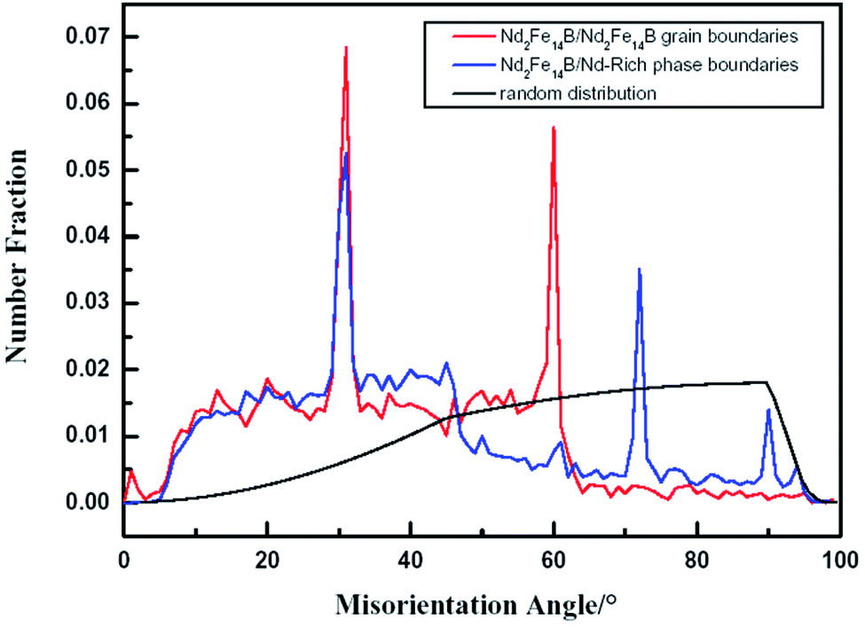 | ||
| Fig. 4 Misorientation angle statistics for the specimen, with red line for Nd2Fe14B/Nd2Fe14B grain boundaries, blue line for Nd2Fe14B/Nd-Rich phase boundaries, and black line for the randomly oriented case. | ||
 | ||
| Fig. 5 The misorientation distribution functions in axis-angle space for illustrating the rotation axes corresponding to the preferential misorientation angles, with units of the contours in MRD: (a) 31°; (b) 60°; (c) 72°. | ||
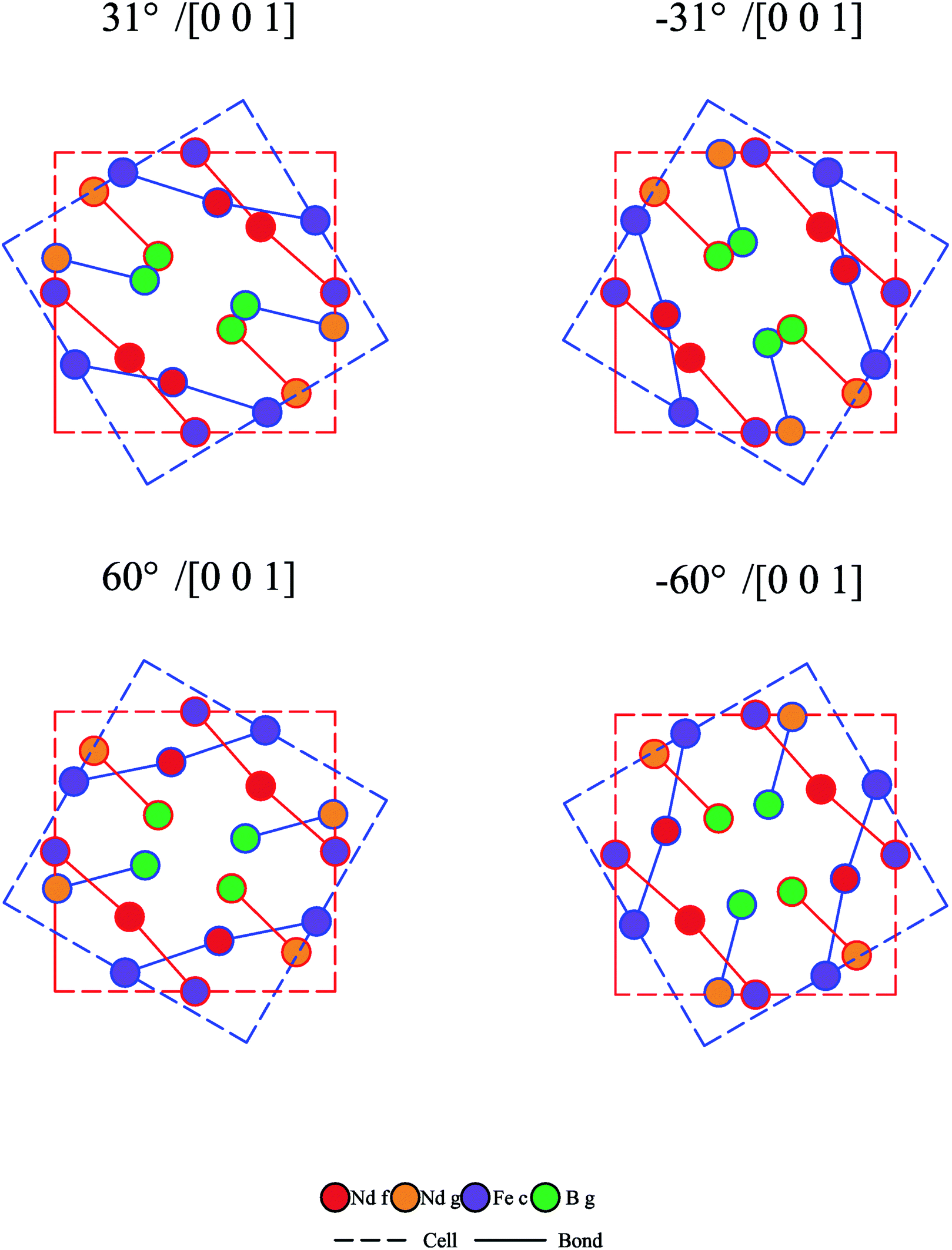 | ||
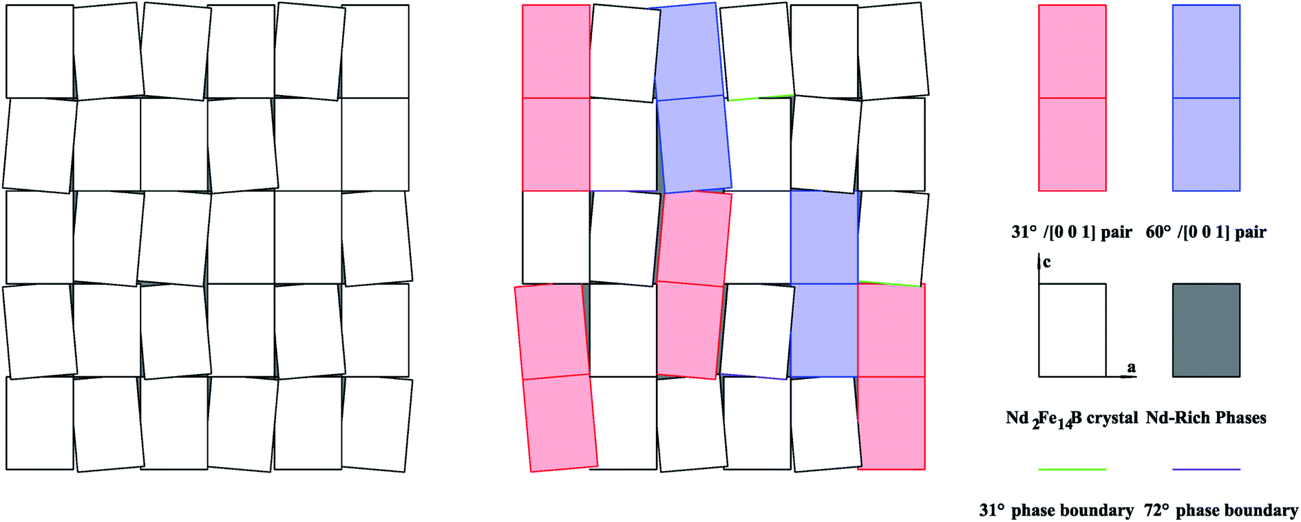
| Fig. 6 The lattice structures of 31°/[0 0 1] and 60°/[0 0 1] misorientations. For each schematic diagram, red lattice refers to the original (0 0 1) plane of a Nd2Fe14B unit cell, and blue lattice refers to the rotated (0 0 1) plane of another Nd2Fe14B unit cell. | ||
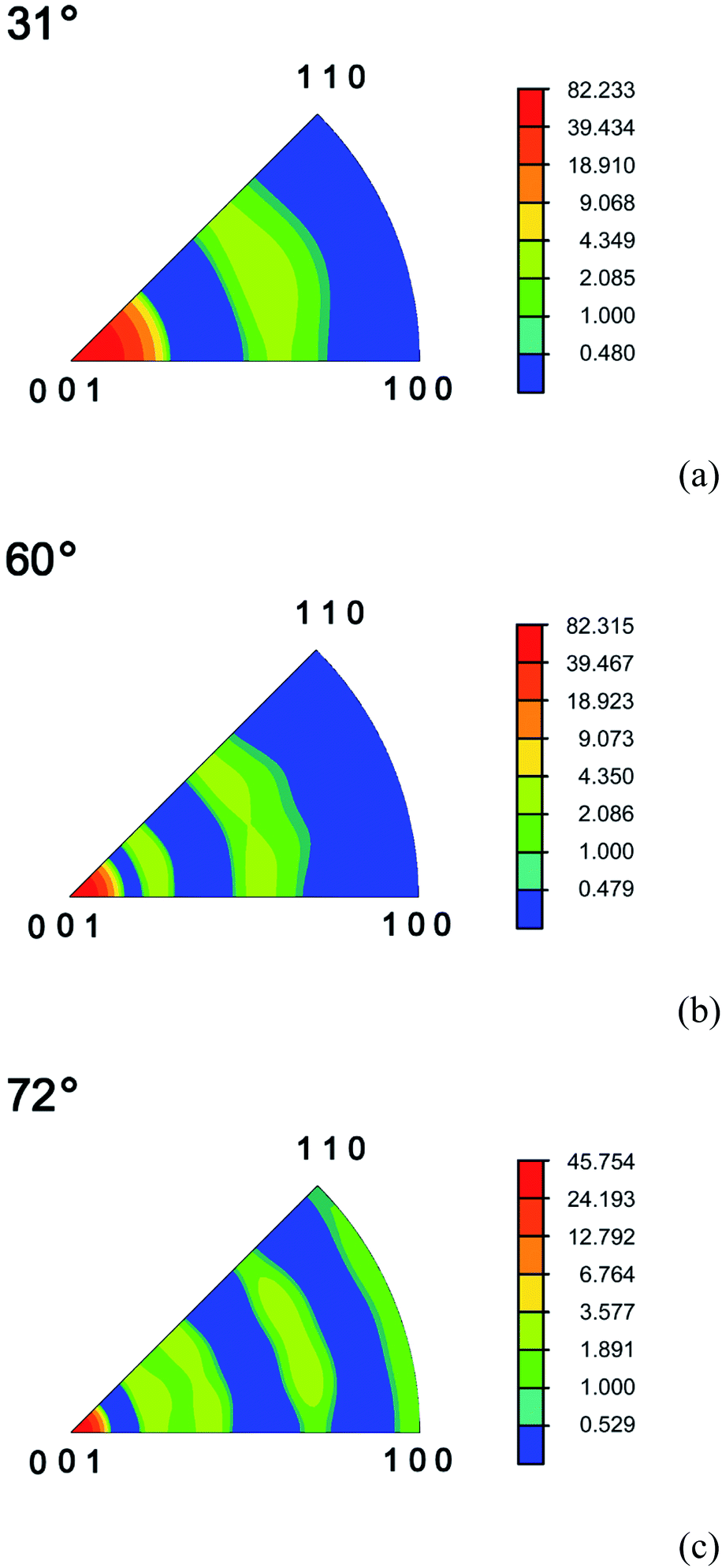
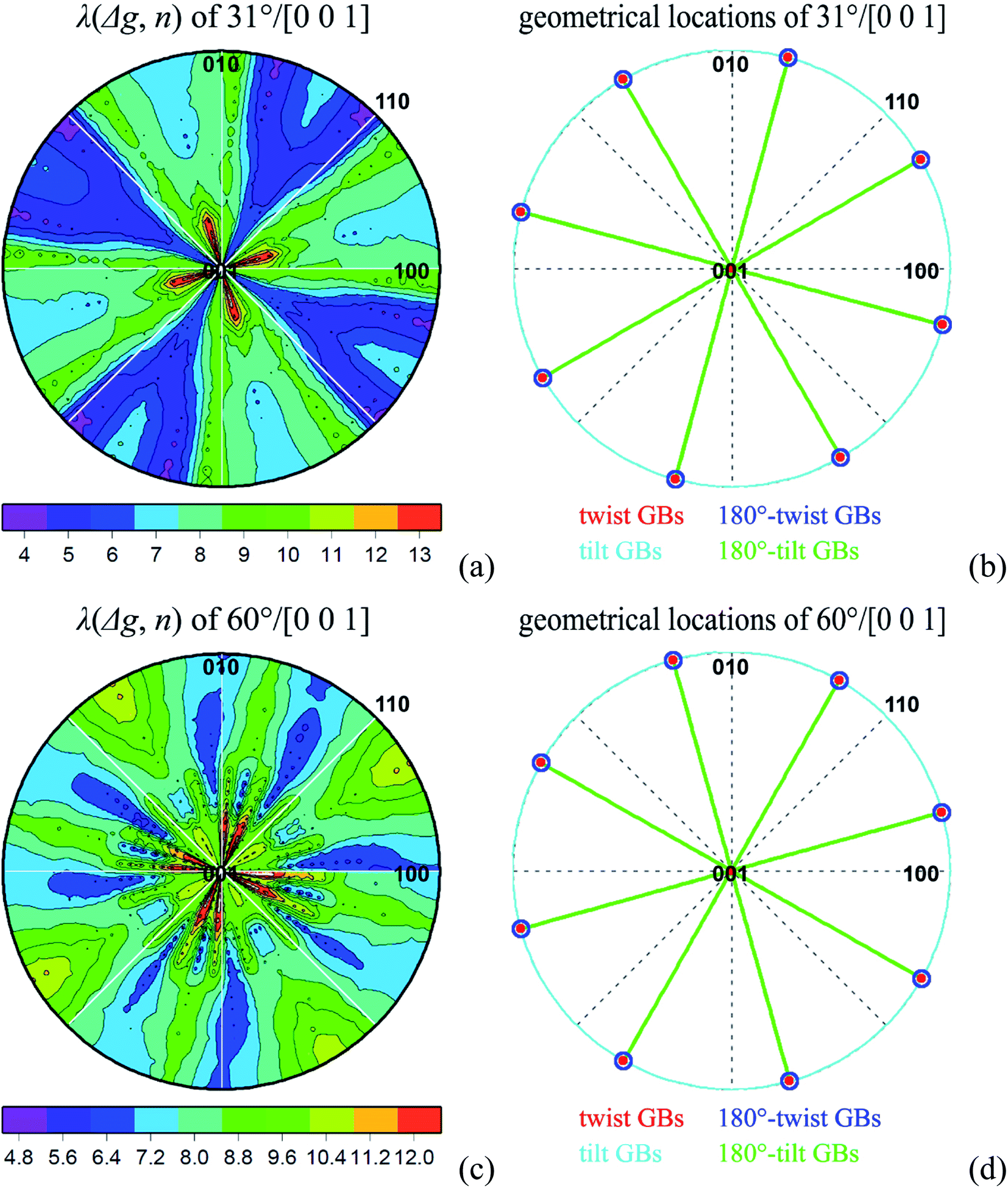
For the preferred 31°/[0 0 1] and 60°/[0 0 1] misorientations in N/N boundaries, λ(Δg, n) results are shown in Fig. 7. For 31°/[0 0 1] misorientation, by comparing with the maximum positions in experimental pole plot (see Fig. 7a) with the geometrically characteristic locations (see Fig. 7b), it can be found that 31°/[0 0 1] has an obvious twist structure mixed with a weak 180°-tilt component; besides, according to the MRD values in Fig. 7a, the occurring frequency of 31°/[0 0 1] is 13 times larger than that in random boundaries. Similarly, for 60°/[0 0 1] misorientation, by comparing with Fig. 7c and d, twist structure spreads along various zone axes can be observed, besides, the occurring frequency of 61°/[0 0 1] is 12 times larger than that in random boundaries.
 | ||
| Fig. 7 GBPD analysis: (a) λ(Δg, n) of 31°/[0 0 1] grain boundary; (b) geometrically characteristic locations of 31°/[0 0 1] grain boundary; (c) λ(Δg, n) of 60°/[0 0 1] grain boundary; (d) geometrically characteristic locations of 60°/[0 0 1] grain boundary. Pole plots are projected along [0 0 1] direction, and the units of the contours are given in MRD. | ||
For N/N boundaries, N/R boundaries and the preferred misorientations in N/N boundaries, their λ(n) results are shown in Fig. 8. For N/N boundaries, peaks at (1 1 0) and (1 1 2) locations indicate that for the measured Nd2Fe14B crystals, their total area of (1 1 0) prismatic planes and (1 1 2) planes is larger than that of (0 0 1) basal planes. For N/R boundaries, peak at (0 0 1) location indicates that Nd2Fe14B crystals are more prone to combine with Nd-Rich phases on (0 0 1) basal planes. Specifically, for N/N boundaries with 31°/[0 0 1] misorientation, (2 1 0) planes are preferred; and for N/N boundaries with 60°/[0 0 1] misorientation, (0 0 1) and (2 1 3) planes are preferred. Due to the border presence of random boundaries, the peak positions in Fig. 8c and d cannot be reflected on Fig. 8a.
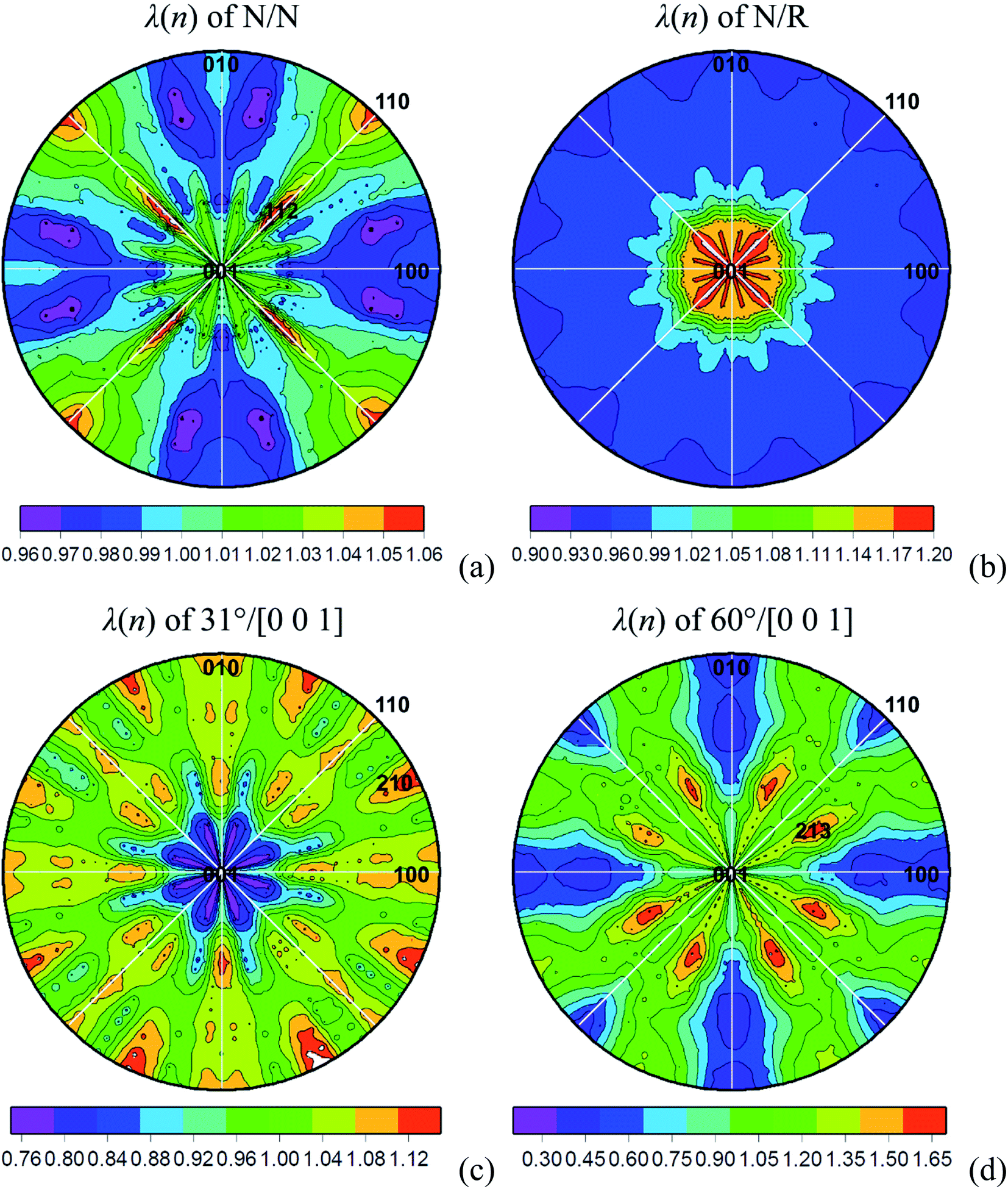 | ||
| Fig. 8 GBPD analysis: (a) λ(n) of Nd2Fe14B/Nd2Fe14B grain boundaries; (b) λ(n) of Nd2Fe14B/Nd-Rich phase boundaries; (c) λ(n) of 31°/[0 0 1] grain boundaries; (d) λ(n) of 60°/[0 0 1] grain boundaries. Pole plots are projected along [0 0 1] direction, and the units of the contours are given in MRD. | ||
4. Discussion
4.1 New cognitions about the boundary networks in NdFeB permanent magnets
For entire N/N boundaries, they occupy the majority in the whole boundaries (see Table 1). Via the N/N boundaries, Nd2Fe14B crystals combine mainly through bi-crystals or tri-crystals pattern. Two specific misorientations, 31°/[0 0 1] and 60°/[0 0 1], are preferred among N/N boundaries, and similar misorientation bias can be found in a previous observation.13 These two misorientations both have a twist structure by referring to [0 0 1] axis and have a relative larger population if compared with random boundaries (see Fig. 4 and 7). Particularly, The 31° misorientation is explained as the standard deviation of Nd2Fe14B crystal alignment distribution.14 Symmetric misorientations would show different local magnetic moments compared with crystal interior or compared with random boundaries.15 Accordingly, although the two preferred misorientations do not present any coincidence lattice site, their symmetric lattice structures (see Fig. 6) might lead to specific magnetic moment state at the corresponding boundary locations.For entire N/R boundaries, they occupy the minority in the whole boundaries (see Table 1). Lattice distortion and reduced local magnetic anisotropy has been observed at N/R boundary locations,16 and the combination approaches at N/R boundary locations, or, the interconnection between Nd-Rich phases, is decisive to obtain higher coercivity.17 In this work, two combination ways at N/R boundary locations are quantificationally clarified. One is spreading wetting of Nd-Rich phases to Nd2Fe14B crystals (indexed by average length in Table 1). Poor grain-boundary wetting might hinder the development of the intrinsic coercivity,18 and small additions of certain elements that concentrated at boundaries can improve the wetting of liquid phase.19 The other is the penetrating of Nd-Rich phases to Nd2Fe14B phase at triple junctions (indexed by triple junction density in Table 1). Liquid phase that penetrates into the N/N boundaries would impact the final intrinsic coercivity via minimizing the exchange interactions between the adjacent Nd2Fe14B crystals.3 For the specific N/R boundaries, two preferred misorientations, 31°/[0 0 1] and 72°/[0 0 1], are observed (see Fig. 4), indicating the two most preferred combination approaches between Nd2Fe14B phase and Nd-Rich phases.6
Orientation texture of habit planes is also observed in the studied specimen. (1 1 0) and (1 1 2) planes occupy a relative large percentage in N/N habit planes, (0 0 1) plane occupies a relative large percentage in N/R habit planes, while (2 1 0) and (2 1 3) planes are preferred among specific N/N boundaries (see Fig. 8). These results indicate that N/N boundaries and N/R boundaries are developed along low-indexed prismatic and basal planes of Nd2Fe14B crystals to minimize interfacial energy, and some similar results can be found in earlier reports.20–22 Orientation texture of habit planes is helpful to explain some anisotropic behaviors, for example, the anisotropic boundary diffusion.23–25
It should be noted that the data in Table 1, Fig. 4, 7 and 8 would alter under different conditions, including: (1) fabrication routines for NdFeB permanent magnets, which would lead to various anisotropies in the magnets; (2) texture degree (means a stronger or a weaker texture) in the magnet, which would lead to various boundary network features, and these features would impact the magnetic anisotropy26 and the size of interaction domains;27 (3) the volume fraction of Nd-Rich phases, which would impact the thickness of Nd-Rich phases between Nd2Fe14B crystals, and (4) the spatial sampling locations: generally speaking, orientation texture of both crystals and boundary planes are weaker if the sampling location is more close to the center of the magnet bulk.28 After taken these factors into account, the statistical methods used in this work are also suitable to other (Nd2Fe14B + Nd-Rich) systems.
4.2 Potential correlations between GBPD and magnetic properties
As an interdisciplinary work, structure–property relationship, or, potential relationship between GBPD and magnetic properties, can be studied based on the new structural information that extracted from the planar EBSD data.For N/R boundaries, Nd-Rich phases magnetically isolate the individual Nd2Fe14B crystals from each other and form shell structure around Nd2Fe14B crystals.31 Accordingly, the composition and width of the boundary could impact the coercivity at N/R boundary locations30 and could determine the magnetic domain wall energy at N/R boundary locations.32 Here, the atomic arrangement of the Nd2Fe14B crystal that very close to the N/R boundary is necessarily distorted over a distance of typically 1 nm, which can be attributed to the redistribution of surface energy that would distort crystal lattice and create stacking faults.3 As to the population of N/R boundaries, it can be controlled by proper processing routines, and the disappearance of N/R boundaries can resulted in a substantial reduction in coercivity.33
The lattice order at either N/N boundaries or N/R boundaries is generally lower than that in the crystal interior, therefore, boundary locations can be regarded as “defects” if compared with crystal interior. Evenly distributed N/R boundaries, or, broader existence of thin-layer-like Nd-Rich phases, can reduce defects on Nd2Fe14B crystal surfaces.3 The lattice distortion of Nd2Fe14B crystal that close to N/R boundary locations can act as nucleation sites for the nucleation of magnetic reversal domains.31 The “defects” structure would also lead to anisotropic behaviors at N/N boundaries or N/R boundaries including reduced local magnetic anisotropy,16 de-pinning of magnetic domain walls on tilted crystals,14 and higher magnetocrystalline anisotropy field when heavy rare earth elements (Dy or Tb) is added.34
Coupling and pinning are the two major mechanisms to explain the coercivity. Coupling is more suitable for sintered NdFeB permanent magnets to obtain high coercivity.34,35 There should exist short-range ferromagnetic coupling across N/N boundaries or N/R boundaries, however, the preferred misorientations observed in this work remind us to pay more attention on long-range magnetostatic interactions, which can hinder the maximizing of intrinsic coercivity when the [0 0 1] orientation texture of Nd2Fe14B crystals is strongest.36 In this work, 6.84% and 5.64% Nd2Fe14B crystals rotate around [0 0 1] axis 31° and 60°, respectively. The preferred misorientations along [0 0 1] axis that between Nd2Fe14B crystals make the lattice sequence more diversified if observed perpendicular to the (0 0 1) plane and as the consequence, the nucleation effect between uncorrelated matrix crystals would present new features on a statistical meaning (see Fig. 9 as the sketch). Pinning is more suitable for hot deformed NdFeB permanent magnets,37 and domain wall pinning at boundary locations is the dominant magnetic hardening mechanism for such magnets.
 | ||
| Fig. 9 Sketch configurations of NdFeB permanent magnets. Left: Nd2Fe14B crystals arrange with strong orientation texture of crystals, but with weak orientation texture of boundary planes. Right: Nd2Fe14B crystals arrange with strong orientation texture of both crystals and boundary planes. | ||
It has been well known that boundaries favor the nucleation of reversed domains,2,30,31,40,42 while coupling that leads to the interaction domains is closely correlated to the boundary structures.41 The preferred boundaries with specific misorientations might be repulsed by the domain wall, whereas the random boundaries might be attracted to the domain wall.15,43 Distribution of N/N boundaries and N/R boundaries simultaneously leads to the textures and anisotropies between crystals. The heterogeneous magnet has locally different crystallographic textures and magnetic domain patterns,38 and degree of texture impacts the scale of the interaction domains.27,41 For sintered NdFeB permanent magnets, the dominant magnetization processes in a field applied parallel to the texture axis are the nucleation of reverse domains and the propagation of easily moveable domain walls.44 In a more general situation, domain walls prefer to stay at the low energy state, for example, trapping at specific boundary locations; thus, the actual position of the domain wall is determined by its energy state.45 Accordingly, coercivity can be improved by increasing the anisotropy field of possible nucleation sites.33
Approaches for enhancing the remanence include the intergranular exchange coupling,46 substitution of low coercivity layer with high magnetization48 and the reinforcing of amorphous (that is, isotropic) attributes at boundary locations.49 On the contrary, factors that can reduce the remanence include reduction of anisotropy constants near boundary locations,7 crystal misalignment during parallel diffusion,30 poor orientation bias of Nd2Fe14B crystals in hot deformed NdFeB permanent magnets (which can leads to the nucleation of reversal magnetic domains38 and the deflection of magnetic moments from the easy direction37) and the addition of heavy rare earth elements (Dy or Tb) (due to the low magnetization of Dy2Fe14B and Tb2Fe14B than that of Nd2Fe14B).48,50
5. Summaries and future perspectives
The work focuses on the misorientations across boundary planes in a sintered NdFeB permanent magnet. The entire boundaries are sorted into N/N boundaries and N/R boundaries. For N/N boundaries, 31°/[0 0 1] and 60°/[0 0 1] misorientations that have twist configurations are preferred, and the two misorientations cannot be explained by the CSL model. For N/R boundaries, two combination ways at N/R boundary locations: spreading wetting or and penetrating of Nd-Rich phases to Nd2Fe14B phase, are quantificationally clarified. Moreover, N/N boundaries favor (1 1 0) and (1 1 2) prismatic habit planes, while N/R boundaries favor (0 0 1) basal habit plane.The anisotropic features of GBPDs would potentially impact the magnetic properties. Regards coercivity, lattice distortion and energy state at boundary locations might impact the coupling and pinning mechanisms. 31° misorientation angle indicates the alignment distribution of Nd2Fe14B crystals and in-turn the angular dependence of the coercive force. Regards domain, the lattice alignment at boundary locations could influence the formation and the size of interaction domains. Regards remanence, the arrangement of magnetic moments close to the boundary locations should be highlighted.
Future works should be include: (1) observations of specific boundaries (via Lorentz microscopy) and domains (via Kerr microscopy);51 (2) make GBPD comparison in serial specimens with different techniques or with relative changes with respect to the current specimen; (3) the role of defects and vacancies should be highlighted when Nd addition is added to the nanocrystalline Nd–Fe–B permanent magnets or when non-equilibrium rapid solidification of the magnet is performed.52 Multiple phases that correlated to Nd addition should be recognized in the EBSD maps; (4) the evolution of the microstructure as well as magnetic properties along with the increase of the temperature should be focused. Although the EBSD camera can not work when the sample is heated to the Curie temperature, the SEM can report the real-time structure of the microstructure. The “in situ SEM” technique would provide beneficial clues to the temperature dependent magnetic properties.
Author contributions
The authors conceive of the presented idea. Xiaokun Yuan performs the computations. Jie Zhu performs the mechanism analysis. The authors discussed the results and contributed to the final manuscript.Conflicts of interest
There are no conflicts to declare.Acknowledgements
The FPA codes are developed by Carnegie Mellon University and can be downloaded at https://mimp.materials.cmu.edu/%7Egr20/stereology. Xiaokun Yuan and Jie Zhu contribute equally to this work. The authors acknowledge support from the State Key Lab of Advanced Metals and Materials 2020-Z08. Computational facility support from Prof. Ming Yue at Beijing University of Technology is also acknowledged.Notes and references
- J. J. Croat, J. F. Herbst, R. W. Lee and F. E. Pinkerton, J. Appl. Phys., 1984, 55, 2078 CrossRef CAS.
- M. Sagawa, S. Fujimura, N. Togawa, H. Yamamoto and Y. Matsuura, J. Appl. Phys., 1984, 55, 2083 CrossRef CAS.
- T. G. Woodcock, Y. Zhang, G. Hrkac, G. Ciuta, N. M. Dempsey, T. Schrefl, O. Gutfleisch and D. Givord, Scripta Mater., 2012, 67, 536–541 CrossRef CAS.
- J. J. Yang, D. T. Zhang, R. C. Zhu, X. C. Xu, D. Wu, Y. Q. Li, W. Q. Liu and M. Yue, Mater. Charact., 2021, 181, 111478 CrossRef CAS.
- D. M. Saylor, B. S. E. Dasher, B. L. Adams and G. S. Rohrer, Metall. Mater. Trans. A, 2004, 35, 1981–1989 CrossRef.
- X. K. Yuan and J. Zhu, Phys. Status Solidi B, 2020, 257, 1900326 CrossRef CAS.
- R. Fischer and H. Kronmuller, J. Appl. Phys., 1998, 83, 3271 CrossRef CAS.
- J. K. Mackenzie and M. J. Thomson, Biometrika, 1957, 44, 205–210 CrossRef.
- M. De Graef, H. Friis Poulsen, A. Lewis, J. Simmons and S. George, Proceedings of the 1st International Conference on 3D Materials Science, Springer International Publishing, Switzerland, AG, 2nd edn, 2012, pp. 119–124 Search PubMed.
- K. Glowinski and A. Morawiec, J. Mater. Sci., 2014, 49, 3936–3942 CrossRef CAS.
- K. K. Zhang, Z. W. Wang, J. He, X. G. Li, W. J. Gong and Y. H. Huang, Int. J. Hydrogen Energy, 2022, 47, 14027–14038 CrossRef CAS.
- D. G. Brandon, Acta Metall., 1966, 14, 1479–1484 CrossRef CAS.
- S. J. Lillywhite, A. J. Williams, B. E. Davies and I. R. Harris, J. Microsc., 2002, 205, 270–277 CrossRef CAS PubMed.
- Y. Matsuura, N. Kitai, R. Ishii, M. Natsumeda, J. Hoshijima and F. Kuniyoshi, J. Magn. Magn. Mater., 2016, 398, 246–252 CrossRef CAS.
- S. Ii, K. Hirayama, K. Matsunaga, H. Fujii and S. Tsurekawa, Scripta Mater., 2013, 68, 253–256 CrossRef CAS.
- G. Hrkac, T. G. Woodcock, C. Freeman, A. Goncharov, J. Dean, T. Schrefl and O. Gutfleisch, Appl. Phys. Lett., 2010, 97, 232511 CrossRef.
- H. S. Amin, T. Ohkuboa, M. Zakotnik, D. Prosperi, P. Afiuny, C. O. Tudor and K. Honoa, J. Alloys Compd., 2017, 694, 175–184 CrossRef.
- T. Tomse, Z. Samardzija, L. Scherf, R. Kessler, S. Kobe, K. Z. Rozman and S. Sturm, J. Magn. Magn. Mater., 2020, 502, 1166504 CrossRef.
- I. R. Harris and A. J. Williams, Z. Metallkd., 2002, 93, 983–990 CrossRef CAS.
- R. Takizawa, M. Itakura, N. Katayama and K. Morimoto, J. Magn. Magn. Mater., 2017, 433, 187–194 CrossRef CAS.
- X. Fu, X. L. Han, Z. W. Du, H. B. Feng and Y. F. Li, J. Rare Earths, 2013, 31, 765–771 CrossRef CAS.
- K. Makita and O. Yamashita, Appl. Phys. Lett., 1999, 74, 2056 CrossRef CAS.
- T. H. Kim, S. R. Lee, S. J. Yun, S. H. Lim, H. J. Kim, M. W. Lee and T. S. Jang, Acta Mater., 2016, 112, 59–66 CrossRef CAS.
- U. M. R. Seelam, T. Ohkubo, T. Abe, S. Hirosawa and K. Hono, J. Alloys Compd., 2014, 617, 884–892 CrossRef CAS.
- T. Q. Zhang, F. G. Chen, Y. Zheng, H. Y. Wen, L. T. Zhang and L. G. Zhou, Scripta Mater., 2017, 129, 1–5 CrossRef CAS.
- K. Guth, T. G. Woodcock, L. Schultz and O. Gutfleisch, Acta Mater., 2011, 59, 2029–2034 CrossRef.
- K. Khlopkov, O. Gutfleisch, D. Hinz, K. H. Muller and L. Schultz, J. Appl. Phys., 2007, 102, 023912 CrossRef.
- D. T. Zhang, X. K. Yuan, M. Yue, D. S. Zhou, J. Zhu and X. X. Gao, CrystEngComm, 2016, 18, 2632–2641 RSC.
- Y. Matsuura, J. Hoshijima and R. Ishii, J. Magn. Magn. Mater., 2013, 336, 88–92 CrossRef CAS.
- S. Sawatzki, T. Schneider, M. Yi, E. Bruder, S. Ener, M. Schonfeldt, K. Guth, B. X. Xu and O. Gutfleisch, Acta Mater., 2018, 147, 176–183 CrossRef CAS.
- G. Hrkac, T. G. Woodcock, K. T. Butler, L. Saharan, M. T. Bryan, T. Schrefl and O. Gutfleisch, Scripta Mater., 2014, 70, 35–38 CrossRef CAS.
- M. Komuro, Y. Satsu and H. Suzuki, IEEE Trans. Magn., 2010, 46, 3831–3833 CAS.
- H. S. Amin, T. Ohkubo and K. Hono, Acta Mater., 2013, 61, 1982–1990 CrossRef.
- Y. J. Wong, H. W. Chang, Y. I. Lee, W. C. Chang, C. H. Chiu and C. C. Mo, J. Magn. Magn. Mater., 2020, 515, 167287 CrossRef CAS.
- F. Maccari, L. Schafer, I. Radulov, L. V. B. Diop, S. Ener, E. Bruder, K. Skokov and O. Gutfleisch, Acta Mater., 2019, 180, 15–23 CrossRef CAS.
- H. S. Chen, Y. Yao, F. Yun, J. T. Qu, Y. F. Li, Z. X. Cheng, Z. X. Ye, S. P. Ringer and R. K. Zheng, J. Magn. Magn. Mater., 2020, 498, 166099 CrossRef CAS.
- Y. Q. Li, X. C. Xu, M. Yue, D. Wu, W. Q. Liu and D. T. Zhang, J. Rare Earths, 2019, 37, 1088–1095 CrossRef CAS.
- Y. Q. Li, X. C. Xu, M. Yue, T. Y. Ma and W. Q. Liu, J. Magn. Magn. Mater., 2020, 498, 166847 CrossRef.
- M. Gusenbauer, J. Fischbacher, A. Kovacs, H. Oezelt, S. Bance, P. P. Zhao, T. G. Woodcock and T. Schrefl, J. Magn. Magn. Mater., 2019, 486, 165256 CrossRef CAS.
- K. Chen, S. Guo, H. L. Zhao, X. D. Fan, F. C. Fan, G. F. Ding, R. J. Chen, X. W. Zheng and A. R. Yan, J. Rare Earths, 2021, 39, 305–311 CrossRef CAS.
- T. G. Woodcock, K. Khlopkov, A. Walther, N. M. Dempsey, D. Givord, L. Schultz and O. Gutfleisch, Scripta Mater., 2009, 60, 826–829 CrossRef CAS.
- W. J. Gong, X. Wang, W. Liu, S. Guo, Z. H. Wang, W. B. Cui, Y. L. Zhu, Y. Q. Zhang and Z. D. Zhang, J. Appl. Phys., 2012, 111, 07A729 CrossRef.
- K. Hampel, D. D. Vvedensky and S. Crampin, Phys. Rev. B: Condens. Matter Mater. Phys., 1993, 47, 4810R CrossRef PubMed.
- K. Khlopkov, O. Gutfleisch, D. Eckert, D. Hinz, B. Wall, W. Rodewald, K. H. Muller and L. Schultz, J. Alloys Compd., 2004, 365, 259–265 CrossRef CAS.
- H. S. Chen, Y. Q. Wang, Y. Yao, J. T. Qu, F. Yun, Y. Q. Li, S. P. Ringer, M. Yue and R. K. Zheng, Acta Mater., 2019, 164, 196–206 CrossRef CAS.
- O. Gutfleisch, J. Phys. D: Appl. Phys., 2000, 33, 157–172 CrossRef.
- S. Sawatzki, T. G. Woodcock, K. Guth, K. H. Muller and O. Gutfleisch, J. Magn. Magn. Mater., 2015, 382, 219–224 CrossRef CAS.
- F. G. Chen, T. Q. Zhang, Y. Zhao, X. L. Wang, C. P. Jiang, J. L. Chen and W. Q. Zhao, J. Alloys Compd., 2021, 867, 159102 CrossRef CAS.
- S. D. Li and B. X. Gu, J. Appl. Phys., 2002, 92, 7514 CrossRef CAS.
- M. H. Choi, S. C. Cho, Y. H. Song, S. K. Park and Y. D. Kim, Curr. Appl. Phys., 2015, 16, 461–467 CrossRef.
- A. K. Choudhary, A. Jansche, T. Grubesa, F. Trier, D. Goll, T. Bernthaler and G. Schneider, Mater. Charact., 2022, 186, 111790 CrossRef CAS.
- N. Emminghaus, C. Hoff, J. Hermsdorf and S. Kaierle, Procedia CIRP, 2020, 94, 211–216 CrossRef.
| This journal is © The Royal Society of Chemistry 2022 |