 Open Access Article
Correlating the effect of preparation methods on the structural and magnetic properties, and reducibility of CuFe2O4 catalysts
Rattabal Khunphonoia,
Pongtanawat Khemthong *bcd,
Chuleeporn Luadthongb,
Sanchai Kuboon
 b,
Chanapa Kongmark
 e,
Nawin Viriya-empikulf,
Pinit Kidkhunthodcg,
Supree Pinitsoontorn
 h and
Kajornsak Faungnawakij
 *b
*b
aDepartment of Environmental Engineering, Khon Kaen University, Khon Kaen 40002, Thailand
bNational Nanotechnology Center (NANOTEC), National Science and Technology Development Agency (NSTDA), Pathumthani 12120, Thailand. E-mail: pongtanawat@nanotec.or.th; kajornsak@nanotec.or.th
cReaserch Network NANOTEC-SUT on Advanced Nanomaterials and Characterization, Suranaree University of Technology, 111 University Avenue, Muang, Nakhon Ratchasima 30000, Thailand
dCenter of Excellence in Environmental Catalysis and Adsorption, Thammasat University, Pathum Thani 12120, Thailand
eSpecialized Center of Rubber and Polymer Materials in Agriculture and Industry, Department of Materials Science, Faculty of Science, Kasetsart University, Bangkok, Thailand
fJoint Graduate School of Energy and Environment, King Mongkut's University of Technology Thonburi, Bangkok, Thailand
gSynchrotron Light Research Institute (Public Organization), 111 University Avenue, Muang, Nakhon Ratchasima 30000, Thailand
hIntegrated Nanotechnology Research Center, Department of Physics, Faculty of Science, Khon Kaen University, Khon Kaen 40002, Thailand
First published on 23rd May 2022
Abstract
CuFe2O4 spinel oxide has attracted research interest because of its versatile practical applications, especially for catalysis. In this study, nanometre-sized CuFe2O4 particles were prepared by three different methods, including nanospace confinement in SBA-15, hard template removal, and sol–gel combustion. The relationship between structure, size, magnetic behaviour, and reducibility of the catalysts was further investigated by various advanced techniques. Samples prepared by impregnation and hard template removal show high surface area and small crystallite size with superparamagnetic behaviour. In contrast, the sol–gel sample exhibits ferromagnetic properties with a large crystallite size and low surface area. Although all samples present a tetragonal crystal structure, the distributions of Fe and Cu cations in tetrahedral and octahedral sites in the spinel structure are different. The reducibility results demonstrate that the supported CuFe2O4/SBA-15 shows the lowest reduction profile. These results could suggest that the synthesis method strongly affects the crystal properties and cation distribution in the spinel structure, microstructure, surface area and reducibility, which are among the most relevant physicochemical properties for the catalytic activity.
1. Introduction
Copper spinel oxides have long attracted attention of researchers because their structural property is suitable for use as precursors or model catalysts.1–4 The structure of copper spinel provided excellent performance in the degradation of oxy-hydrocarbons at relatively lower temperatures of 200–350 °C, compared to other types of Cu-based catalysts.2,5 A series of Cu-spinel species of CuMn2O4,6 ZrO2–CuZn(Al2O3),7 and CuFe2O4–SiO2 catalysts1 have been investigated lately. Among them, CuFe2O4 is considered to be a promising catalyst for methanol steam reforming because of the abundance of Cu and Fe in nature8 and its active ability for hydrogen production. However, the CuFe2O4 spinel catalysts typically possessed low surface area and their copper particles became sintered after high temperature calcination, resulting in insufficient active sites. It is well known that the activity of CuFe2O4 spinel is greatly dependent on Cu particle size and its dispersion. Well dispersed Cu particles with a slow rate of sintering can promote high hydrogen production yield.We recently examined CuFe2O4 catalysts prepared by a urea–nitrate combustion method for dimethyl ether steam reforming and found that these catalysts were highly active in spite of their low surface area.2,9 Nevertheless, the CuFe2O4 spinel in the form of nanopores and nanoparticles should be developed to provide a new structure with higher surface area, leading to better catalytic performance. A common method to meet this requirement is impregnating mesoporous silica powders with the desired salt precursors. A hard template for crystal growth of porous metal spinel oxide is also one of many interesting techniques for preparing high surface area materials, especially mesoporous metal oxides.10 Both methods have been used as a powerful strategy for producing crystalline nanoporous materials having a vast potential for applications in the catalysis.11–13 Some advanced techniques as a block copolymer templates have been demonstrated for controlling the size, morphology, and shape of nanoparticles.14–16 To the best of our knowledge, however, there are a few studies reporting on the relationship between structure, magnetic behaviour, and reduction behaviour of CuFe2O4 spinel prepared with different methods. Thus, in this research, the relationships of those behaviours have been examined. We have expected that this investigation could provide an information for preparing a suitable catalyst, regarding to a significant role of preparation methods on structural behaviour and catalytic performance of CuFe2O4 catalysts.
2. Experimental
2.1 Catalyst preparation
The CuFe2O4/SBA-15 was prepared by impregnation method using nitrate solutions of Cu and Fe with a 0.4 molar ratio.8 Firstly, the nitrate salts were dissolved in 0.8 mL of deionized (DI) water and placed in a vacuum oven at room temperature for 1 h. The powder of mesoporous SBA-15 was slowly added to the mixed nitrates solution and stirred until the mixture became homogenized (the total weight ratio of nitrate salts and mesoporous SBA-15 was 1![[thin space (1/6-em)]](https://www.rsc.org/images/entities/char_2009.gif) :
:![[thin space (1/6-em)]](https://www.rsc.org/images/entities/char_2009.gif) 1). Later on, the mixture was placed on hot plate at 70 °C for 1 h, ground and dried in vacuum oven overnight. After that, the red sample was calcined at 750 °C for 15 h with heating rate of 1 °C min−1 (the final metal loading was 27% wt. and denoted as CuFe2O4/SBA-15).
1). Later on, the mixture was placed on hot plate at 70 °C for 1 h, ground and dried in vacuum oven overnight. After that, the red sample was calcined at 750 °C for 15 h with heating rate of 1 °C min−1 (the final metal loading was 27% wt. and denoted as CuFe2O4/SBA-15).
2.2 Characterizations
The phase and crystallinity of samples were confirmed by powder X-ray diffraction (XRD; Bruker, D8 ADVANCE) with Cu Kα radiation at 40 kV and 40 mA, increment of 0.02° per second, step time of 0.5 s over the scan range of 10° < 2θ < 80°. The specific surface area and pore volume were determined using nitrogen adsorption–desorption isotherm technique (Bel, Belsorp-max) at 77 K. Each sample was outgassed overnight at 300 °C before measuring. The reduction profiles were carried out using temperature-programmed reduction (TPR; Quantachrome Instruments, CHEMBET-Pulsar). About 25 mg of the calcined catalyst was heated under atmosphere of 5% H2/Ar with 10 °C min−1 heating rate and 30 mL min−1 flow rate to final temperature of 800 °C. The morphologies of the catalysts were examined with transmission electron microscopy (TEM; JEOL, JEM-2100). The samples were dispersed in methanol media and then deposited on a Cu grid. Magnetic hysteresis loops were recorded at room temperature using a vibrating sample magnetometry (VSM; LAKE SHORE VSM 7404, Lake Shore Cryotronics, Inc., USA) with a maximum magnetic field of 10 kG. The geometry, local environment, and structural properties of CuFe2O4 were solved by X-ray absorption spectroscopy (XAS) technique. Transmission XAS spectra were collected at Fe and Cu K-edges at the SUT-NANOTEC-SLRI XAS beamline (BL5.2; electron energy of 1.2 GeV; bending magnet; beam current of 80–150 mA; 1.1 to 1.7 × 10¹¹ photon per s) of the Synchrotron Light Research Institute, Public Organization, Thailand.18 For the acquisition of all spectra, a Ge (220) double crystal monochromator with an energy resolution (ΔE/E) of 2 × 10⁻⁴ was used. Energy calibrations were carried out using Fe foil (7112 eV) and Cu foil (8979 eV). In the X-ray absorption near edge structure (XANES) region, the step size was 0.02 eV with a second integration time. The extended X-ray absorption fine structure (EXAFS) region was set to scan to the maximum of 10k. The data reduction and EXAFS curve fitting were performed using the Athena and Arthemis programs which are included in an IFEFFIT package.19,202.3 Methanol steam reforming evaluation
The catalytic activity of the prepared catalysts was demonstrated for methanol steam reforming using a tubular reactor under atmospheric pressure. A 0.2 g of each catalyst was packed in a tubular quartz cell and sandwiched with quartz wool on both sides then placed inside the furnace. Prior to the experiments, the catalyst was reduced in 10% H2 balanced with N2 at 350 °C with a flow rate of 40 mL min−1 for 3 h. After the reduction was completed, the temperature was maintained at 200 °C under N2 flow. A mixture of methanol and steam (steam/carbon ratio = 2) was injected to a pre-heater at 150 °C to generate a gas feed stock using syringe pump with an injection rate of 100 mL min−1. After that, the gas feed stock was introduced through the reactor by N2 carrier gas with a flow rate of 100 mL min−1. The reaction temperature was held in a range of 200–375 °C. The derived gaseous products in the supplied and reformed gases after experiment were collected at 3 °C using a condenser. The gas compositions were analyzed by online gas chromatography (GC) equipped with a thermal conductivity detector (VARIAN, CP-4900). A Poraplot U column was used to separate methanol, and CO2. A capillary molecular sieve 5 Å column was applied for H2, O2, N2, CH4, and CO separations. The catalytic activity was evaluated by the H2 production rate.3. Results and discussion
3.1 Characterization of CuFe2O4 catalyst
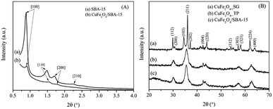 | ||
| Fig. 1 (A) Low angle-XRD patterns of SBA-15 and CuFe2O4/SBA-15 composite; (B) wide angle-XRD patterns of CuFe2O4/SBA-15, CuFe2O4_TP and CuFe2O4_SG. | ||
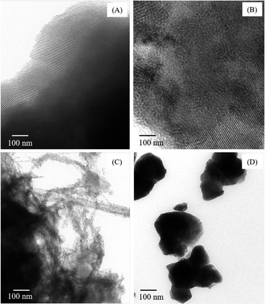
Fig. 1(B) shows wide-angle XRD spectra of calcined samples with different preparation methods. Most of the diffraction peaks corresponded to the spinel phase of CuFe2O4, manifested by the sharp characteristic reflection planes. This lattice parameter for tetragonal spinel CuFe2O4 is in good agreement with that previously reported.22 In addition, XRD peaks of copper oxides and iron oxides were not detected in any samples. This would indicate that the synthesis methods were feasible to effectively prepare a pure CuFe2O4 phase. The catalyst prepared via sol–gel method showed sharp and intense reflection peaks. This was probably due to particle agglomeration during calcination. On the other hand, the XRD patterns of CuFe2O4/SBA-15 composite and CuFe2O4_TP show much broader peaks. Overlapping peaks of XRD profiles were evident and became dominant. This discernible feature indicated that small crystalline sizes without sintering of spinel oxides were formed, comparing to the sol–gel method. It should be noted that the SBA-15 has promoted and assisted the dispersion of CuFe2O4 on the surface. A closer look at these XRD peak profiles reveals a sharp 004 reflection which would suggest that the SBA-15 may favor the growth of CuFe2O4 crystal along one direction. The structure of spinel oxide (CuFe2O4_TP) was also maintained after leaching out of SBA-15. In addition, the SBA-15 did not present any diffraction patterns at high angles due to its amorphous nature of pore walls.
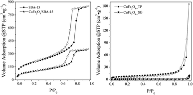 | ||
| Fig. 3 N2 adsorption–desorption isotherms of spinel and SBA-15 samples; adsorption (black) and desorption (white). | ||
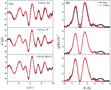
| Sample name | Paths | N | Occupancy (%) | R (Å) | σ2 | BET* (m2 g−1) |
|---|---|---|---|---|---|---|
| a Where N = coordination number, R = distance to neighboring atom, * SBA-15 = 685 m2 g−1. | ||||||
| CuFe2O4_SG | Fe–O1octa | 2.8 | 48.2 | 1.96 | 0.006 | 1 |
| Fe–Feocta | 2.8 | 2.92 | 0.009 | |||
| Fe–Cuocta | 2.8 | 3.37 | 0.003 | |||
| Fe–O2octa | 2.8 | 3.38 | 0.009 | |||
| Fe–O1tetra | 2.1 | 51.8 | 2.05 | 0.020 | ||
| Fe–Fetetra | 3.2 | 3.63 | 0.004 | |||
| Fe–Cutetra | 3.2 | 3.82 | 0.009 | |||
| Fe–O2tetra | 6.5 | 3.86 | 0.040 | |||
| CuFe2O4_TP | Fe–O1octa | 3.8 | 63.4 | 1.96 | 0.002 | 30 |
| Fe–Feocta | 3.8 | 2.94 | 0.009 | |||
| Fe–Cuocta | 3.8 | 3.41 | 0.004 | |||
| Fe–O2octa | 3.8 | 3.47 | 0.004 | |||
| Fe–O1tetra | 1.5 | 36.6 | 1.84 | 0.002 | ||
| Fe–Fetetra | 2.2 | 3.73 | 0.004 | |||
| Fe–Cutetra | 2.2 | 3.92 | 0.004 | |||
| Fe–O2tetra | 4.4 | 3.83 | 0.004 | |||
| CuFe2O4/SBA-15 | Fe–O1octa | 5.1 | 84.3 | 1.96 | 0.014 | 336 |
| Fe–Feocta | 5.1 | 2.98 | 0.001 | |||
| Fe–Cuocta | 5.1 | 3.39 | 0.004 | |||
| Fe–O2octa | 5.1 | 3.44 | 0.027 | |||
| Fe–O1tetra | 0.6 | 15.7 | 1.96 | 0.001 | ||
| Fe–Fetetra | 0.9 | 3.64 | 0.002 | |||
| Fe–Cutetra | 0.9 | 3.52 | 0.011 | |||
| Fe–O2tetra | 1.9 | 3.69 | 0.002 | |||
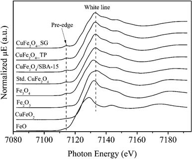 | ||
| Fig. 5 Fe K-edge XANES spectra of CuFe2O4_SG, CuFe2O4_TP and CuFe2O4/SBA-15 samples compared with standard materials of CuFe2O4, Fe3O4, Fe2O3, CuFeO2, and FeO. | ||
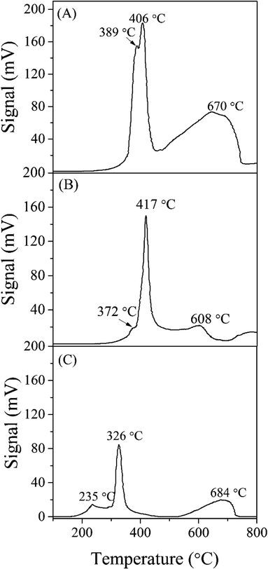
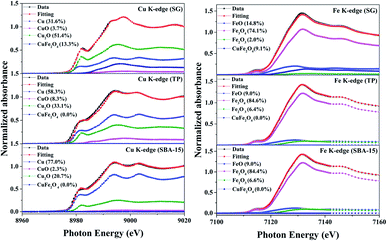
To further investigate the reductive species in the reduced samples, Cu and Fe K-edges XANES spectra were collected and have been displayed in Fig. 8. In the Cu K-edge, the edge energies of the reduced samples are the same as the Cu foil, indicating the presence of metallic copper. A closer look at XANES spectra, the white line feature and shoulder were observed in CuFe2O4_SG, indicating dominating copper oxides in the samples. Here, the intense white line peak and the dominant shoulder in the CuFe2O4_SG could be assigned to the 1s → 4p transition of Cu2O. To analyze the composition of copper species in the samples, the linear combination fit analysis was applied. The quantification by linear combination fitting yields a mixture of metallic Cu, Cu2O and CuO in each sample (Fig. 8). It was found that the copper ions in CuFe2O4/SBA-15 were highly reduced to the state of zero, while the CuFe2O4_SG was partially reduced at 350 °C. In case of Fe K-edge, the XANES fit of Fe K-edge revealed that the catalysts were fully remained in the oxide forms. The structure of iron was gradually change from CuFe2O4 to typically iron oxides like FeO, Fe3O4, and Fe2O3. These results are consistent with the H2-TPR which ascribe that iron species in CuFe2O4 spinel are more resistant toward reduction.
3.2 Testing of CuFe2O4 spinel for steam reforming of methanol (SRM)
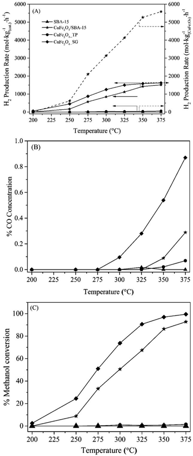
Prior to demonstrate the catalytic performance, the blank test of pure siliceous SBA-15 was carried out with the same space velocity. The result showed a negligible catalytic activity of the siliceous SBA-15. In Fig. 9, the catalytic results of each catalyst were represented in the term of H2 production rate and methanol conversion as a function of temperature. After H2 reduction at 350 °C, it was observed that the rate of methanol conversion and H2 production rate per gram of catalyst were in order of CuFe2O4_SG > CuFe2O4/SBA-15 > CuFe2O4_TP. However, when considering the H2 production rate per gram of active CuFe2O4 spinel, the CuFe2O4/SBA-15 catalyst showed the highest H2 production rate (∼5500 mol kg(CuFe2O4)−1 h−1) at the reaction temperature of 375 °C. It is suggested that the improved turnover rate of CuFe2O4/SBA-15 was due to the high dispersion of copper spinel particles on the SBA-15 support. Moreover, the mesoporous SBA-15 silica support could obstruct the sintering process of nano-metallic copper during the reaction and enhanced the catalytic reaction.Comparison between CuFe2O4_SG and CuFe2O4_TP catalysts, it was very interesting that the lower surface of CuFe2O4_SG provided the highest catalytic activity (100% conversion and H2 production rate of ∼1600 mol kgCat−1 h−1 at 375 °C) compared to the higher surface area of CuFe2O4_TP. The CuFe2O4_TP exhibits the lowest yield of H2 production rate (<10 mol kgCat−1 h−1) with % methanol conversion of less than 1%. This result suggested that almost no metallic copper was generated from the reduction of the needle-like CuFe2O4_TP. To verify this concept, the catalytic evaluation of CuFe2O4_SG and CuFe2O4_TP was also studied under the reduction temperature of 420 °C as indicated by TPR results that CuFe2O4_SG and CuFe2O4_TP catalysts could be completely reduced at temperature higher than 350 °C. However, the catalytic activity of these two catalysts after reducing at 420 °C was dramatically decreased in their performance. This could be attributed to the fact that the reduced copper was sintered to form bulky particles during the reduction process. Hence, the reduction temperature at 350 °C was enough for reduction of CuFe2O4_SG and CuFe2O4_TP in this reaction. Nevertheless, it was an unexpected result that the needle-like CuFe2O4_TP was not active for the methanol steam reforming. This issue should be further investigated and reported in next.
4. Conclusions
The preparation methods strongly affected on cation distribution and physicochemical properties of CuFe2O4. The CuFe2O4 supported on SBA-15 exhibited the superparamagnetic behaviour with well-crystallized tetragonal structure and high reducibility. However, upon removal of SBA-15 from the CuFe2O4/SBA-15, the needle-like of CuFe2O4_TP with high surface area, but the reduction requires a high temperature as well as sol–gel combustion method.Conflicts of interest
There are no conflicts to declare.Acknowledgements
This work was supported by the Thailand Research Fund (TRF) and NANOTEC through the Young Research Grants to Pongtanawat Khemthong (Grant No. TRG5780192). This work was also conducted under the research on development of novel technologies for safe agriculture by Faculty of Engineering, Khon Kaen University which has received funding support from Fundamental Fund 2022 (the National Science, Research and Innovation Fund (NSRF), Thailand).Notes and references
- S. Kameoka, T. Tanabe and A. P. Tsai, Catal. Lett., 2005, 100, 89–93 CrossRef CAS.
- K. Faungnawakij, N. Shimoda, T. Fukunaga, R. Kikuchi and K. Eguchi, Appl. Catal., B, 2009, 92, 341–350 CrossRef CAS.
- K. Faungnawakij, N. Shimoda, N. Viriya-empikul, R. Kikuchi and K. Eguchi, Appl. Catal., B, 2010, 97, 21–27 CrossRef CAS.
- N. Shimoda, K. Faungnawakij, R. Kikuchi and K. Eguchi, Appl. Catal., A, 2010, 378, 234–242 CrossRef CAS.
- K. Faungnawakij, N. Shimoda, T. Fukunaga, R. Kikuchi and K. Eguchi, Appl. Catal., A, 2008, 341, 139–145 CrossRef CAS.
- J. Papavasiliou, G. Avgouropoulos and T. Ioannides, Catal. Commun., 2005, 6, 497–501 CrossRef CAS.
- S. Patel and K. Pant, J. Porous Mater., 2006, 13, 373–378 CrossRef CAS.
- S.-C. Yang, W.-N. Su, S. D. Lin, J. Rick, J.-H. Cheng, J.-Y. Liu, C.-J. Pan, D.-G. Liu, J.-F. Lee and T.-S. Chan, Appl. Catal., B, 2011, 106, 650–656 CrossRef CAS.
- K. Faungnawakij and N. Viriya-Empikul, Appl. Catal., A, 2010, 382, 21–27 CrossRef CAS.
- W. Yue and W. Zhou, Chem. Mater., 2007, 19, 2359–2363 CrossRef CAS.
- H. Yen, Y. Seo, R. Guillet-Nicolas, S. Kaliaguine and F. Kleitz, Chem. Commun., 2011, 47, 10473–10475 RSC.
- M.-b. Zheng, J. Cao, S.-t. Liao, J.-s. Liu, H.-q. Chen, Y. Zhao, W.-j. Dai, G.-b. Ji, J.-m. Cao and J. Tao, J. Phys. Chem. C, 2009, 113, 3887–3894 CrossRef CAS.
- A.-H. Lu and F. Schüth, C. R. Chim., 2005, 8, 609–620 CrossRef CAS.
- C. D. Sewell, Z. Wang, Y.-W. Harn, S. Liang, L. Gao, X. Cui and Z. Lin, J. Mater. Chem. A, 2021, 9, 20375–20384 RSC.
- L. Gao, X. Cui, Z. Wang, C. D. Sewell, Z. Li, S. Liang, M. Zhang, J. Li, Y. Hu and Z. Lin, Proc. Natl. Acad. Sci. U. S. A., 2021, 118, e2023421118 CrossRef CAS PubMed.
- X. Li, J. Iocozzia, Y. Chen, S. Zhao, X. Cui, W. Wang, H. Yu, S. Lin and Z. Lin, Angew. Chem., Int. Ed., 2018, 57, 2046–2070 CrossRef CAS PubMed.
- V. Meynen, P. Cool and E. Vansant, Microporous Mesoporous Mater., 2009, 125, 170–223 CrossRef CAS.
- P. Kidkhunthod, Adv. Nat. Sci.: Nanosci. Nanotechnol., 2017, 8, 035007 Search PubMed.
- M. Newville, J. Synchrotron Radiat., 2001, 8, 96–100 CrossRef CAS PubMed.
- B. Ravel and M. Newville, J. Synchrotron Radiat., 2005, 12, 537–541 CrossRef CAS PubMed.
- M. G. Sorolla, M. L. Dalida, P. Khemthong and N. Grisdanurak, J. Environ. Sci., 2012, 24, 1125–1132 CrossRef CAS.
- C. Luadthong, P. Khemthong, W. Nualpaeng and K. Faungnawakij, Appl. Catal., A, 2016, 525, 68–75 CrossRef CAS.
- G. Tompsett, L. Krogh, D. Griffin and W. Conner, Langmuir, 2005, 21, 8214–8225 CrossRef CAS PubMed.
- B. Issa, I. M. Obaidat, B. A. Albiss and Y. Haik, Int. J. Mol. Sci., 2013, 14, 21266–21305 CrossRef CAS PubMed.
- P. Laokul, V. Amornkitbamrung, S. Seraphin and S. Maensiri, Curr. Appl. Phys., 2011, 11, 101–108 CrossRef.
- R. Yadav, I. Kuřitka, J. Vilčáková, J. Havlica, J. Másilko, L. Kalina, J. Tkacz, M. Hajdúchová and V. Enev, Structural, dielectric, electrical and magnetic properties of CuFe2O4 nanoparticles synthesized by honey mediated sol–gel combustion method and annealing effect, 2017 Search PubMed.
- C. Caizer and M. Rai, Magnetic Nanoparticles in Human Health and Medicine: Current Medical Applications and Alternative Therapy of Cancer, Wiley, 2021 Search PubMed.
- V. Blanco-Gutiérrez, F. Jiménez-Villacorta, P. Bonville, M. J. Torralvo-Fernández and R. Sáez-Puche, J. Phys. Chem. C, 2011, 115, 1627–1634 CrossRef.
- S. Calvin, M. Shultz, L. Glowzenski and E. Carpenter, J. Appl. Phys., 2010, 107, 024301 CrossRef.
- T. Tangcharoen, W. Klysubun, J. T-Thienprasert and C. Kongmark, J. Solid State Chem., 2020, 292, 121695 CrossRef CAS.
- S. Patange, S. E. Shirsath, G. Jangam, K. Lohar, S. S. Jadhav and K. Jadhav, J. Appl. Phys., 2011, 109, 053909 CrossRef.
- P. Khemthong, C. Kongmark, N. Kochaputi, S. Mahakot, S. Rodporn and K. Faungnawakij, Inorg. Chem., 2019, 58, 6584–6587 CrossRef CAS PubMed.
- M. Estrella, L. Barrio, G. Zhou, X. Wang, Q. Wang, W. Wen, J. C. Hanson, A. I. Frenkel and J. A. Rodriguez, J. Phys. Chem. C, 2009, 113, 14411–14417 CrossRef CAS.
- V. Krishnan, R. K. Selvan, C. O. Augustin, A. Gedanken and H. Bertagnolli, J. Phys. Chem. C, 2007, 111, 16724–16733 CrossRef CAS.
- S. Kameoka, T. Tanabe and A. P. Tsai, Appl. Catal., A, 2010, 375, 163–171 CrossRef CAS.
- N. Iwasa and N. Takezawa, Top. Catal., 2003, 22, 215–224 CrossRef CAS.
| This journal is © The Royal Society of Chemistry 2022 |

