 Open Access Article
Novel ultralong and photoactive Bi2Ti4O11/TiO2 heterojunction nanofibers toward efficient textile wastewater treatment
Jermyn Juaya,
Jia-Cheng E. Yang b,
Hongwei Baia and
Darren Delai Sun
 *a
*a
aSchool of Civil and Environmental Engineering, Nanyang Technological University, Singapore 639798, Singapore. E-mail: ddsun@ntu.edu.sg
bCAS Key Laboratory of Urban Pollutant Conversion, Institute of Urban Environment, Chinese Academy of Sciences, Xiamen 361021, China
First published on 7th September 2022
Abstract
The elimination of dyes from textile wastewater with a lower carbon footprint is highly contingent on the design of green catalysts. Here, we innovatively developed ultralong one-dimensional Bi2Ti4O11/TiO2 heterojunction nanofibers via electrospinning so as to photocatalytically degrade dyes efficiently and sustainably through the utilisation of renewable solar irradiation. The heterostructured Bi2Ti4O11/TiO2 nanofibers exhibited desirable activity in the visible light region through the slight shift of the absorption edge to a longer wavelength. The Bi2Ti4O11/TiO2 nanofibers calcined at 550 °C had a lower optical band gap (3.08 eV) than that of the pure TiO2 (3.32 eV), as evidenced by their higher photocatalytic degradation kinetics of a model dye (Acid Orange 7) (2.5 times greater than those of pure TiO2). The enhanced visible light photocatalytic performance arose from the formation of both the Bi2Ti4O11/TiO2 heterojunction and the effective separation of photogenerated holes and electrons. The employment of ultralong Bi2Ti4O11/TiO2 heterojunction nanofibers for dye removal/decolourisation under visible light is an efficient, cost effective and sustainable solution, which will provide significant insights for practical textile wastewater treatment in view of practical engineering applications.
1. Introduction
Wastewater effluents from textile production are considered as one of the largest contributors to water pollution. These effluents have several unique characteristics, such as (1) heavy colour issues due to the presence of various dyes, (2) high chemical oxygen demand leading to high pollution issues, (3) high salinity and heavy metal concentration etc., which make them not readily biodegradable.1 There are many combinations of conventional wastewater treatment technologies that employ physical, chemical and biological treatment techniques to treat this textile wastewater.2 It has been found that approaches such as activated carbon,3 coagulation/flocculation,4 and membrane technologies5 could separate the dye contaminants from the aqueous phase to the solid phase, but without completely eliminating them. Therefore, the disadvantages of current techniques are obvious due to their high cost, low treatment efficiency and associated secondary pollution issues for further disposal. To some extent, the resultant sludges are toxic by-products and large carbon footprints are inevitably involved for their further disposal,6 thus accentuating the need for developing ‘cleaner’ alternative approaches.7 With the growing emphasis on sustainability and advancement in technology, the use of TiO2 photocatalysts has begun to receive increasing attention.8–10 The employment of nanostructured TiO2 with renewable solar energy as the energy input for photocatalytic oxidation (PCO) decontamination offers an efficient and cost-effective method for the treatment of this industrial wastewater.11There are several developed approaches used for the synthesis of TiO2 photocatalyst such as hydrothermal methods,12 electrochemical anodization13 and electrochemical deposition,14,15 of which the one step electrospinning has shown considerable potential as an innovative and ‘green’ alternative technology,16 especially in the field of fabricating one-dimensional (1D) nanostructured materials with large length-to diameter ratio and excellent properties for pollutants adsorption, degradation and removal. In general, 1D TiO2 nanofibers obtained through electrospinning exhibit significant benefits such as high surface-to-volume ratio, open porous structure and unique material properties allowing it to be easily recycled thus permitting it to be employed in various industries.16 However, there are two key limitations of TiO2 which limits its potential. Firstly, the generation of the photo-excited holes and electrons can only be achieved by UV irradiation (λ < 380 nm) which renders the use of solar irradiation inefficient due to wide band gap of TiO2 (3.2 eV anatase).10,17 Secondly, the life time of the photo-excited electrons and holes have limited mobility arising from the recombination of electron–hole pair.17,18
Therefore, in order to narrow the band gap and improve its photocatalytic performance, materials chemists and environmental engineers have widely explored the use of various metal oxides such as Cu,19–22 Sr,23 Fe,24 Cd,25 Zn,26,27 etc. Recently, bismuth titanates (BTO)-oriented catalysts have drawn a significant amount of emphasis due to their unique optical properties and potential applications,.17,18,28 These nanostructured bismuth nanomaterials have shown to be valuable photocatalysts that can effectively and efficiently break down various model dye pollutant in water under UV29–31 and visible light irradiation.26,32,33 However, the majority of these BTO catalysts are synthesised from solid state reactions involving multiple stages at high reaction temperature and pressure.17,34 To date, there has been little knowledge on BTO and TiO2 heterostructures synthesised through electrospinning approaches. Herein, Bi2Ti4O11/TiO2 heterostructure nanofibers were unprecedentedly designed and prepared by an effective one-step electrospinning approach to study their PCO decontamination efficiency for treating textile wastewaters. A key benefit to the heterostructured BTO and TiO2 from the one-step electrospinning lies in the fact that the uniform mixing of BTO and TiO2 precursor at molecular level will facilitate the close contact between Bi and TiO2 in the formed materials, which will greatly improve the electrons transfer allowing for better photocatalytic activity.17,28
2. Experimental
2.1 Synthesis of Bi2Ti4O11/TiO2 heterostructure nanofibers
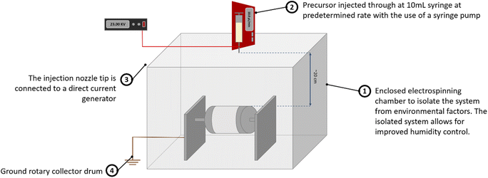
![[thin space (1/6-em)]](https://www.rsc.org/images/entities/char_2009.gif) 300
300![[thin space (1/6-em)]](https://www.rsc.org/images/entities/char_2009.gif) 000) and bismuth(III) nitrate pentahydrate (Bi(NO3)·5H2O) were of analytical grade and used directly without further purification. Tetra n-butyl orthotitanate (Ti(OCH2CH2CH2CH3)4) as a precursor of TiO2 was of reagent grade.
000) and bismuth(III) nitrate pentahydrate (Bi(NO3)·5H2O) were of analytical grade and used directly without further purification. Tetra n-butyl orthotitanate (Ti(OCH2CH2CH2CH3)4) as a precursor of TiO2 was of reagent grade.The precursor solution for electrospinning was prepared as follows: firstly, in a volume ratio of 11![[thin space (1/6-em)]](https://www.rsc.org/images/entities/char_2009.gif) :
:![[thin space (1/6-em)]](https://www.rsc.org/images/entities/char_2009.gif) 3
3![[thin space (1/6-em)]](https://www.rsc.org/images/entities/char_2009.gif) :
:![[thin space (1/6-em)]](https://www.rsc.org/images/entities/char_2009.gif) 1, ethanol, acetic acid and DMF were mixed to achieve a homogenous solution. Subsequently, 3 wt% of bismuth salt was added to the above mixture and stirred until a clear solution was obtained. 20 wt% of PVP was then dissolved before the titanium component was finally added to the mixture with being magnetically mixed for 6 hours to obtain a clear gel solution for electrospinning.
1, ethanol, acetic acid and DMF were mixed to achieve a homogenous solution. Subsequently, 3 wt% of bismuth salt was added to the above mixture and stirred until a clear solution was obtained. 20 wt% of PVP was then dissolved before the titanium component was finally added to the mixture with being magnetically mixed for 6 hours to obtain a clear gel solution for electrospinning.
2.2 Photocatalytic activities of Bi2Ti4O11/TiO2 nanofibers
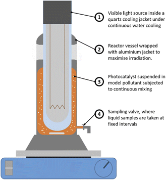
Here, a typical industrial dye Acid Orange 7 (AO7) was used as a probe pollutant for evaluating the photodegradation efficiency. The photocatalytic oxidation test was conducted in the reactor vessel shown in Fig. 2. A 20 mg L−1 of AO7 (model pollutant) was first prepared before adding 0.5 g L−1 of Bi2Ti4O11/TiO2 heterostructure nanofiber photocatalyst into the solution. This solution was magnetically stirred in the reactor for 120 min to ensure homogeneity of the photocatalyst in the solution and establish an adsorption equilibrium between the pollutant and nanofiber photocatalyst. Thereafter, the irradiation source was turned on and at pre-determined intervals of illumination, 2.0 mL of reaction solution was drawn and the decrease in concentration of the AO7 solution was measured using a spectrophotometer (UV-1800 Shimadzu© UV-vis spectrophotometer).The designed photoreactor comprises of 2 components, the first being the outer reactor vessel in which the Bi2Ti4O11/TiO2 nanofibers as a photocatalyst was suspended. The second component, the inner quartz cooling jacket where a 360 W high pressure sodium lamp (Riko, HNL-360A) with a luminous efficacy of 80–125 lm W−1 was used as the UV-vis light source. The cooling jacket was constantly cooled using a peristaltic pump to ensure that optimum operation temperature.35
2.3 Characterisation of Bi2Ti4O11/TiO2 heterostructure nanofibers
The structural morphology of the Bi2Ti4O11/TiO2 heterostructure nanofibers were characterised with a field emission scanning electron microscope (Field Emission Scanning Electron Microscope JSM-7600F). The elemental distribution of the as prepared nanofiber was studied with the use of energy-dispersive X-ray spectroscopy (EDX – Oxford Instrument, X-max, 80 mm2). The high-resolution transmission electron microscope (TEM) images were acquired using a TEM JOEL-2010HR. The X-ray diffraction patterns were recorded on a Bruker D8 advance X-ray diffractometer (XRD) with monochromated high intensity Cu Kα radiation (λ = 1.5418 Å). The BET (Brunauer, Emmett and Teller) specific surface area and BJH (Barret–Joyner–Halenda) pore size distribution of the heterostructure nanofiber were assessed at liquid nitrogen temperature (77 K) using Quadrasorb evo™. The samples were degassed in a MasterPrep® Degasser at 160 °C for 8 hours prior to the analysis. The UV-vis diffused reflectance (DR) spectra was recoded on a UV-2600 Shimadzu UV-vis and using BaSO4 as a reference.3. Results and discussion
3.1 Material characterisation
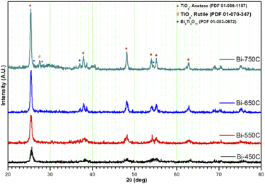 | ||
| Fig. 3 XRD diffraction patterns of Bi2Ti4O11/TiO2 heterostructure nanofibers calcined at various temperatures. | ||
| Samples | BET specific surface area (m2 g−1) | Estimated pore diameter (nm) estimated with BJH | Full width at half maximum (deg) | Anatase TiO2 crystallite size (nm) |
|---|---|---|---|---|
| Bi-450C | 57.56 | 3.63 | 0.67 | 12.64 |
| Bi-550C | 34.96 | 3.64 | 0.55 | 15.57 |
| Bi-650C | 12.29 | 3.03 | 0.38 | 22.19 |
| Bi-750C | 6.39 | 2.66 | 0.34 | 24.94 |
| TiO2 NF (550C) (anatase phase) | 27.582 | 3.63 | 0.56 | 15.18 |
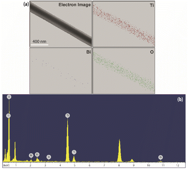 | ||
| Fig. 4 (a) Elemental mapping for the selected area of Ti, Bi and O elements, (b) EDX spectrum of electron image shown in (a). | ||
Moreover, the EDX analysis also revealed that the weight ratio of the bismuth component was 3.34 wt%, which corresponds to the amount of bismuth precursor added to the gel as described in previous Section 2.1.1. This finding supports the fact of weak diffraction peaks for the Bi2Ti4O11 species as a consequence of the low concentration and well dispersed nature of the Bi precursor.35
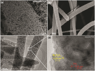
The TEM image in Fig. 5(c) exemplifies the detailed porous microstructure, which was also observed in Fig. 5(b). The porous structure is conducive for photocatalysis as it provides channels for the reactants to adsorb onto the surface of the nanofibers. In addition, the TEM image shows the nanofiber comprises of granular nanocrystals denoting good crystallinity which is essential to facilitate charge transfer to achieve efficient photocatalytic activity. As presented in Fig. 5(d), the high magnification HRTEM image clearly reveals the distinguished interface contact and continuity between the lattice fringes with interplanar spacing of 0.325 nm and 0.295 nm. These two distinctive lattice fringes correspond to the (101) plane of anatase TiO238 and the (171) plane of Bi2Ti4O11, respectively,39 which substantiates the fact that the nanofiber is formed of a heterostructure consisting of anatase TiO2 and the Bi2Ti4O11 crystalline phase.
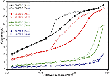 | ||
| Fig. 6 Nitrogen adsorption/desorption isotherms for calcined Bi2Ti4O11/TiO2 heterostructure nanofibers. | ||
Additionally, from the BET analysis, it can be noted that the formation of the heterojunction between the Bi2Ti4O11 and TiO2 phases enlarged the surface area of the nanofibers. The heterostructure nanofiber showed a 25% increase in the surface area as compared to the pure TiO2 nanofiber. This increase in BET specific surface area was due to the presence of the well dispersed bismuth elements in the electrospinning precursor, which allowed for the formation of additional active sites comprising of the Bi2Ti4O11 crystal phase after thermal treatment. This confirms that the formation of the heterostructure structure through the heterojunction has increased the amounts of available reactions sites for the access of reactants for photocatalysis. Furthermore, the observed increase in BET specific surface area also promotes the adsorption and mass transfer of the pollutants. Hence, considering these advantages it is plausible that the heterojunction formed in the Bi2Ti4O11/TiO2 heterostructure nanofiber would improve the photocatalytic performance as compared to pure TiO2 nanofibers.
3.2 Performance evaluation
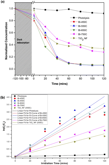
![[thin space (1/6-em)]](https://www.rsc.org/images/entities/char_2009.gif) 000 kinds of dyes in the industry and AO7 is a water-soluble dye which is considered as a pervasive pollutant due to its potential to form co-contaminants for nitrates. To model the photocatalytic degradation, Langmuir–Hinshelwood kinetics was applied.43 As shown in eqn (1), the reaction rate (r) can be described as function of the degree of substrate coverage (θ):
000 kinds of dyes in the industry and AO7 is a water-soluble dye which is considered as a pervasive pollutant due to its potential to form co-contaminants for nitrates. To model the photocatalytic degradation, Langmuir–Hinshelwood kinetics was applied.43 As shown in eqn (1), the reaction rate (r) can be described as function of the degree of substrate coverage (θ):
 | (1) |
 | (2) |
 | (3) |
| Sample ID | Degradation rate, k (min−1) | Standard deviation | R2 | Estimate band gap, Eg (eV) |
|---|---|---|---|---|
| Photolysis | 1.04 × 10⁻² | ± 7.58 × 10⁻⁵ | 0.9639 | — |
| Bi-450C | 2.80 × 10⁻² | ± 2.17 × 10⁻³ | 0.9594 | 3.08 |
| Bi-550C | 3.38 × 10⁻² | ± 2.44 × 10⁻³ | 0.9645 | 3.08 |
| Bi-650C | 3.01 × 10⁻² | ± 2.48 × 10⁻³ | 0.9543 | 3.12 |
| Bi-750C | 1.71 × 10⁻² | ± 1.28 × 10⁻³ | 0.9622 | 3.11 |
| TiO2 NF − 550C | 1.28 × 10⁻² | ± 1.06 × 10⁻³ | 0.9538 | 3.32 |
The heterostructure nanofiber calcined at 750 °C (Bi-750C) has a BET specific surface area of 6.39 m2 g−1, much lower than that of the nanofiber calcined at 550 °C (Bi-550C, 34.96 m2 g−1). This indicates that the increase in calcination temperature might have led to the collapse of the microporous structure (which exists at lower temperatures),45,46 thus resulting in an inferior mass transport between the model pollutant and the heterostructure nanofiber. The less porousness makes more difficult for the pollutant to enter the pore channel of the heterostructure nanofiber.42,47 Consequently, this resulted in a lower photocatalytic efficiency due to the decrease in the active sites available for reactions (arising from the smaller BET specific surface area).
The Bi2Ti4O11/TiO2 heterostructure nanofibers showed a greater photocatalytic efficiency in degrading AO7 under visible light irradiation. As reflected in Table 2, the photo degradation rate of AO7 by Bi-550C was 2.64 times greater than that of pure TiO2 nanofiber. This is possibly attributed to the enhanced visible light absorption arising from the heterojunction formed between the Bi2Ti4O11 and the TiO2 anatase phase (cf. Fig. 5(d)). The formation of this heterojunction coupled with the optimised geometry from the microporous structure of the nanofiber allowed for the travel of electron–hole pairs to a shorter diffused pathway to reach the active surface sites of the photocatalyst, therefore ensuring a more effective suppression of the electron–hole recombination.33,48 Moreover, the diffuse reflectance analysis revealed that the heterostructure nanofibers possessed a lower estimated optical band gap (ranging from 3.08 to 3.11 eV) than that of the pure TiO2 nanofiber (3.32 eV) (Table 2). The lower band gap (due to the presence of the Bi2Ti4O11) can be interpreted as an improved light absorption capacity in the visible-light region.49
3.3 Photocatalytic stability for practical application
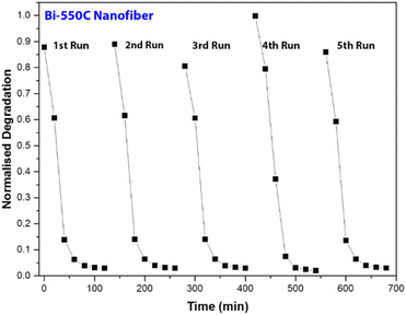
Using Bi-550C as a representative catalyst, we investigated the photocatalytic stability of the Bi2Ti4O11/TiO2 heterostructure nanofiber under visible light irradiation. The selected samples were repeatedly used after separation via vacuum filtration, and the results are presented in Fig. 8. As shown, there were no significant changes in the photocatalytic activity of Bi-550C after five cycles as the degradation efficiencies of AO7 remained virtually unchanged. This indicates that Bi-550C has good structural stability under visible light irradiation for the photocatalytic decomposition of organic pollutants. Therefore, it is viable to employ these photocatalysts for practical applications as the Bi2Ti4O11/TiO2 heterostructure nanofibers have long lifespan for reuse.3.4 Mechanism revelation
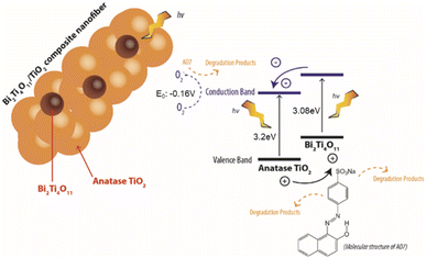
As shown in Fig. 9, upon harvesting the of photon energy from the simulated solar irradiation, it leads to the excitation of electrons which travels from the valence band (VB) to the conduction band (CB) leaving holes in the VB of the Bi2Ti4O11 phase. Here due to the heterojunction formed between the phases, the electrons from the CB of the Bi2Ti4O11 could transfer to the CB of the anatase TiO2.17,28 As these photoexcited electrons and holes separate and migrate to the surface of the photocatalyst, it reacts with the aqueous phase generating reducing and oxidising agents degrade AO7. The holes would react with adsorbed hydroxyl groups in the aqueous phase or on the surface of the photocatalyst forming oxidation species such as (OH˙).17 Meanwhile, the electrons would react with adsorbed O2 to produce O2− and further degrade AO7. Consequently, through this effective transfer of electrons it would reduce the recombination of the electrons and hole due to the formation of the heterojunction formed between the Bi2Ti4O11/TiO2. Therefore, the enhanced photocatalytic activity under visible light irradiation for the Bi2Ti4O11/TiO2 can be ascribed to: (1) the enhanced visible light absorption, (2) the good adsorption of model pollutants and (3) the efficient separation of photogenerated charge carriers.50
4. Conclusions
This study demonstrated a successful and facile method to synthesize an enhanced visible light driven nanofiber photocatalysts with a heterojunction formed between the Bi2Ti4O11 (171 phase) and anatase TiO2 (101 phase). Experimental results revealed that the Bi2Ti4O11/TiO2 heterostructure nanofiber showed superior photocatalytic performance than compared to pure TiO2 in the degradation of the model textile dye AO7 under visible light irradiation. First, the Bi phase was evenly distributed through the heterostructure nanofiber, indicating that the uniform mixing occurring at the molecular level allowed for the formation of heterojunction between the highly crystalline Bi2Ti4O11 phase and the anatase TiO2 phase. Second, owing to the formation of this heterojunction, it shifted the absorption edge to a longer wavelength. Third, the presence of the Bi2Ti4O11 titanate phase coupled with the morphological characteristics of the nanofibers allowed for a more effective transfer of electrons through the reduced recombination of electrons and holes. Fourth, the heterostructure nanofibers have demonstrated excellent photo-stability after undergoing multiple reuses, signifying the robust nature of the heterostructure photocatalyst for practical engineering applications with the use of sustainable visible light or solar utilisation. In view for practical engineering application in treating wastewater through fully exploiting the abundant solar light in sustainable manner, it is believed that the developed Bi2Ti4O11/TiO2 heterojunction nanofibers may not only be limited for the employment of textile wastewater degradation but also can be used for other photocatalytic application in environmental remediation.Conflicts of interest
There are no conflicts to declare.Acknowledgements
We acknowledge Interdisciplinary Graduate School (IGS) and Nanyang Environment Water Research Institute (NEWRI) for their financial support. We also thank Mr Lua Shun Kuang from IGS for his help and valuable suggestions. The scholarship provided by IGS and NEWRI is appreciated.Notes and references
- B. Neppolian, H. C. Choi, S. Sakthivel, B. Arabindoo and V. Murugesan, Chemosphere, 2002, 46, 1173–1181 CrossRef CAS.
- K. Malachova, Z. Rybkova, H. Sezimova, J. Cerven and C. Novotny, Water Res., 2013, 47, 7143–7148 CrossRef CAS PubMed.
- C. Zaharia and D. Suteu, Environ. Sci. Pollut. Res., 2013, 20, 2226–2235 CrossRef CAS PubMed.
- V. Golob, A. Vinder and M. Simonič, Dyes Pigm., 2005, 67, 93–97 CrossRef CAS.
- J. Wu, M. A. Eiteman and S. E. Law, J. Environ. Eng., 1998, 124, 272–277 CrossRef.
- J. Liu, J. Zheng, G. Yue, H. Li, Z. Liu, Y. Zhao, N. Wang, C. Sun and Z. Cui, RSC Adv., 2022, 12, 10258–10266 RSC.
- T. Robinson, G. McMullan, R. Marchant and P. Nigam, Bioresour. Technol., 2001, 77, 247–255 CrossRef CAS.
- S.-Y. Lee and S.-J. Park, J. Ind. Eng. Chem., 2013, 19, 1761–1769 CrossRef CAS.
- M. A. Lazar, S. Varghese and S. S. Nair, Catalysts, 2012, 2, 572–601 CrossRef CAS.
- A. Fujishima and K. Honda, Nature, 1972, 238, 37–38 CrossRef CAS.
- V. K. Gupta, R. Jain, A. Mittal, T. A. Saleh, A. Nayak, S. Agarwal and S. Sikarwar, Mater. Sci. Eng., Proc. Conf., 2012, 32, 12–17 CrossRef CAS.
- H. Kominami, J. Kato, Y. Takada, Y. Doushi, B. Ohtani, S. Nishimoto, M. Inoue, T. Inui and Y. Kera, Catal. Lett., 1997, 46, 235–240 CrossRef CAS.
- J. Ng, X. Zhang, T. Zhang, J.-H. Pan, J.-H. A. Du and D. D. Sun, J. Chem. Technol. Biotechnol., 2010, 85, 1061–1066 CrossRef CAS.
- C. Natarajan and G. Nogami, J. Electrochem. Soc., 1996, 143, 1547–1550 CrossRef CAS.
- X. Zan and H. Bai, J. Electrochem. Soc., 2021, 168, 027504 CrossRef CAS.
- S. Ramakrishna, K. Fujihara, W.-E. Teo, T. Yong, Z. Ma and R. Ramaseshan, Mater. Today, 2006, 9, 40–50 CrossRef CAS.
- S. S. Lee, H. Bai, S. C. Chua, K. W. Lee and D. D. Sun, J. Clean. Product., 2021, 298, 126671 CrossRef CAS.
- H. Bai, Z. Liu and D. D. Sun, J. Mater. Chem., 2012, 22, 18801–18807 RSC.
- S. S. Lee, H. Bai, Z. Liu and D. D. Sun, Water Res., 2013, 47, 4059–4073 CrossRef CAS PubMed.
- Y.-C. Pu, W.-H. Lin and Y.-J. Hsu, Appl. Catal., B, 2015, 163, 343–351 CrossRef CAS.
- Y.-H. Chiu and Y.-J. Hsu, Nano Energy, 2017, 31, 286–295 CrossRef CAS.
- M.-Y. Kuo, C.-F. Hsiao, Y.-H. Chiu, T.-H. Lai, M.-J. Fang, J.-Y. Wu, J.-W. Chen, C.-L. Wu, K.-H. Wei, H.-C. Lin and Y.-J. Hsu, Appl. Catal., B, 2019, 242, 499–506 CrossRef CAS.
- H. Bai, J. Juay, Z. Liu, X. Song, S. S. Lee and D. D. Sun, Appl. Catal., B, 2012, 125, 367–374 CrossRef CAS.
- M. Periyasamy, S. Sain, U. Sengupta, M. Mandal, S. Mukhopadhyay and A. Kar, Mater. Adv., 2021, 2, 4843–4858 RSC.
- A. T. Nguyen, W.-H. Lin, Y.-H. Lu, Y.-D. Chiou and Y.-J. Hsu, Appl. Catal., A, 2014, 476, 140–147 CrossRef CAS.
- Y.-C. Chen, T.-C. Liu and Y.-J. Hsu, ACS Appl. Mater. Interfaces, 2015, 7, 1616–1623 CrossRef CAS PubMed.
- W.-H. Lin, Y.-H. Chiu, P.-W. Shao and Y.-J. Hsu, ACS Appl. Mater. Interfaces, 2016, 8, 32754–32763 CrossRef CAS.
- H. Bai, Z. Liu and D. D. Sun, J. Am. Ceram. Soc., 2013, 96, 942–949 CrossRef CAS.
- C. Wang, C. Shao, L. Wang, L. Zhang, X. Li and Y. Liu, J. Colloid Interface Sci., 2009, 333, 242–248 CrossRef CAS PubMed.
- Y.-H. Chiu, T.-F. M. Chang, C.-Y. Chen, M. Sone and Y.-J. Hsu, Catalysts, 2019, 9, 430 CrossRef CAS.
- Y.-A. Chen, Y.-T. Wang, H. S. Moon, K. Yong and Y.-J. Hsu, RSC Adv., 2021, 11, 12288–12305 RSC.
- H. Bai, Z. Liu and D. D. Sun, ChemPlusChem, 2012, 77, 941–948 CrossRef CAS.
- H. Bai, Z. Liu and D. D. Sun, Chem. Commun., 2010, 46, 6542–6544 RSC.
- J. Hou, Z. Wang, S. Jiao and H. Zhu, J. Hazard. Mater., 2011, 192, 1772–1779 CrossRef CAS PubMed.
- S. Xu, J. Ng, A. J. Du, J. Liu and D. D. Sun, Int. J. Hydrogen Energy, 2011, 36, 6538–6545 CrossRef CAS.
- H. Bai, Z. Liu, L. Liu and D. D. Sun, Chem. – Eur. J., 2013, 19, 3061–3070 CrossRef CAS PubMed.
- L. Duan, H. Zhu, M. Li, X. Zhao, Y. Wang, Y. Zhang and L. Yu, J. Alloys Compd., 2021, 889, 161694 CrossRef.
- J. Ng, S. Xu, X. Zhang, H. Y. Yang and D. D. Sun, Adv. Funct. Mater., 2010, 20, 4287–4294 CrossRef CAS.
- H. Shi, H. Tan, W.-b. Zhu, Z. Sun, Y. Ma and E. Wang, J. Mater. Chem. A, 2015, 3, 6586–6591 RSC.
- K. S. W. Sing, J. Porous Mater., 1995, 2, 5–8 CrossRef CAS.
- P. Yang, D. Zhao, D. I. Margolese, B. F. Chmelka and G. D. Stucky, Nature, 1998, 396, 152–155 CrossRef CAS.
- J. H. Pan, H. Dou, Z. Xiong, C. Xu, J. Ma and X. S. Zhao, J. Mater. Chem., 2010, 20, 4512–4528 RSC.
- X. Wang and T.-T. Lim, Appl. Catal., B, 2010, 100, 355–364 CrossRef CAS.
- J. Ng, J. H. Pan and D. D. Sun, J. Mater. Chem., 2011, 21, 11844–11853 RSC.
- S. Madhugiri, B. Sun, P. G. Smirniotis, J. P. Ferraris and K. J. Balkus, Microporous Mesoporous Mater., 2004, 69, 77–83 CrossRef CAS.
- Y.-F. Lin and Y.-J. Hsu, Appl. Catal., B, 2013, 130–131, 93–98 CrossRef CAS.
- P.-Y. Hsieh, Y.-H. Chiu, T.-H. Lai, M.-J. Fang, Y.-T. Wang and Y.-J. Hsu, ACS Appl. Mater. Interfaces, 2019, 11, 3006–3015 CrossRef CAS.
- T. Cao, Y. Li, C. Wang, C. Shao and Y. Liu, Langmuir, 2011, 27, 2946–2952 CrossRef CAS PubMed.
- J. Zhou, Z. Zou, A. K. Ray and X. S. Zhao, Ind. Eng. Chem. Res., 2007, 46, 745–749 CrossRef CAS.
- Q. Guo, C. Zhou, Z. Ma and X. Yang, Adv. Mater., 2019, 31, 1901997 CrossRef CAS PubMed.
| This journal is © The Royal Society of Chemistry 2022 |

