 Open Access Article
Electrochemical deposition of flower-like nanostructured silver particles with a PVA modified carbon cloth cathode
Bo-An Zhao,
Wen-Fang Cai,
Kai-Bo Pu,
Ji-Rui Bai,
Jia-Yao Gao and
Yun-Hai Wang *
*
Department of Environmental Science and Engineering, School of Energy and Power Engineering, Xi'an Jiaotong University, Xi'an 710049, China. E-mail: wang.yunhai@mail.xjtu.edu.cn
First published on 8th August 2022
Abstract
A novel electrochemical method for preparing flower-like nanostructured silver particles using polyvinyl alcohol (PVA) modified carbon cloth as a cathode is reported. The method does not involve the use of any morphological control agents in aqueous solution. The morphology of the silver nanoparticles obtained was studied using scanning electron microscopy (SEM) and X-ray diffractometry (XRD). The effects of the operating conditions on the deposited silver nanoparticles were investigated. It was found that PVA concentration for carbon cloth modification had a significant effect on the deposited silver morphology. With 1% PVA modification, current density of 10 μA cm−2 and silver nitrate concentration of 1 mM, a flower-like nanostructured silver with petal thickness of 100 nm can be prepared. With the reaction proceeding, silver nanocrystals nucleated on the cathode in a few seconds, then the nuclei grew and the rudimental flower-like silver started to form in 1 min. The perfect flower-like nanostructure of silver was formed in 20 min. However overlong reaction time led to micrometer sized blocks. The specific silver nanostructure growth might be attributed to the silver ion concentration gradient caused by reaction and diffusion rate and the effects of PVA.
1. Introduction
In recent years, noble metal nanostructures of different morphologies have attracted great attention due to their prominent antibacterial,1–3 catalytic,4–6 optical and magnetic properties.7–9 Among these noble materials, silver nanostructures attracted lots of research interest due to their narrow plasmon resonance and super hydrophobic surface. The researchers have synthesized diverse shapes of silver nanostructures, such as rods, cubes, wires, dendrites, polyhedra, triangular plates, etc. by different approaches.10–19 Controllable preparation of silver nanostructures is very important to obtain high-performance products. To date numerous protocols have been developed to synthesize various silver nanoparticles, which include membrane-templated syntheses, solution-based chemical reduction syntheses in micellar media or with capping agents, step edge decoration, photo induced conversion, electrochemical syntheses, etc.12–14,17–24The electrochemical method attracted more attention recently because it has the advantages of pure products and the possibility of regulating the nanoparticle morphology by controlling the current density without expensive equipment or additional chemical agents. The key to the success of electrochemical methods is the right choice of electrodes and the process conditions.25 In previous studies, silver crystals with different morphologies were synthesized by using different electrodes. Sharma et al. proposed a simple approach to the creation of highly dispersed electrocatalytically active silver micro-structured dendrites on indium tin oxide (ITO).26 Cherevko et al. synthesized Ag foam using Pt/Ti/Si electrode galvanostatically and the average pore size of the foam was 20–45 μm with nanosized branches.27 Khaydarov et al. used bulk Ag metal as anode and cathode to transform it to polyhedron-shaped Ag particles and plates. Silver crystal growth on the cathode in the electrochemical process was shown to result in nanostructures consisting of agglomerated silver nanoparticles with the sizes below 40 nm.25 Mazur et al. prepared silver nanoflakes and nanorods by potentiostatic reduction of silver ions on highly oriented pyrolytic graphite (HOPG) electrode from acetonitrile solution containing mercaptopropionic acid.28 Recently, broad applicability of nanostructured silver has received researchers' extensive attention. Molina et al. synthesized Ag nano-flowers with enhanced photocatalytic and antibacterial activities.29 It has been widely reported nano-silver as surface enhanced Raman scattering substrates for rapid detection of trace organic pollutants.30–33
Carbon cloth is widely used as current collector because of its good conductivity, excellent mechanical strength and chemical stability, and the rough surface is also conducive to the deposition of silver.34 Polyvinyl alcohol can change the surface energy of crystals. The surface energy can affect the equilibrium shape of crystals and plays an important role in faceting, roughening, and crystal growth phenomenon.35 At the same time, it can be used as adhesive in industry.36
In addition, compared with nano-silver of other morphologies, flower-like Ag nanostructures have significant antibacterial activities,29 electrical conductivities37 and catalytic properties.38 They exhibit strong electromagnetic enhancement effects and amplified SERS signals.39 However, their preparation is seldom investigated via electrochemical method.40 To the best of the authors' knowledge, there's one paper reported the fabrication of flower-like silver particles by electrochemical approach using anodic aluminum oxide electrode,33 but no reports on the flower-like silver nanoparticles preparation on modified carbon cloth. It is still a challenge to controllable prepare special morphology silver nanoparticles on carbon cloth. In this article, a novel electrochemical method using polyvinyl alcohol (PVA) modified carbon cloth as cathode to prepare flower-like nanostructured silver particles is presented. This methodology not only involves the synthesis of flower-like nanostructured silver particles by electrochemical deposition on carbon cloth electrode without template's assistance, but also employs PVA, a commonly used adhesive as electrodes modifier to prepare controllable silver nanoparticles. This work is aimed to figure out the appropriate electrochemical reaction parameters to synthesize the flower-like nanostructured silver and discuss the crystal growth's regular pattern for this morphology.
2. Experimental section
2.1 Materials
Silver nitrate was purchased from Tianjin Tiangan Chemical Technology Development Co., Ltd (Tianjin, China), while PVA (alcoholysis degree 98–99%, polymerization degree 2400–2500) and potassium nitrate were purchased from Aladdin. All chemicals were of analytical grade and were used without further purification. The electrochemical workstation was CS310 (CorrTest Instruments, China). Deionized (DI) water was used throughout the experiments.2.2 Modification of carbon cloth
Carbon cloth was washed with acetone, ethanol and deionized water before the modification and then cut into 2 cm × 1.5 cm pieces. The PVA aqueous solution with a certain mass concentration was prepared by mixing completely a certain amount of PVA with DI water at 75 °C and cooling down to room temperature for further use. The carbon cloth was then immersed in the above solution for 24 h and took out and air-dried. One side of the dried carbon cloth was encapsulated with insulating silicone glue and the other side would expose to the electrolyte as the working electrode.2.3 Synthesis of silver particles by electrochemical reaction
Silver particles were synthesized in a single chamber electrochemical reactor with silver nitrate aqueous solution as silver source and electrolyte without any other supporting electrolyte addition. Three electrode system with modified carbon cloth as working electrode, platinum wire as counter electrode and Ag/AgCl as reference electrode was used. In order to prevent the interference of chloride ions in the reference electrode, an external salt bridge filled with potassium nitrate solution was sleeved on the reference electrode. The reactor was connected with the electrochemical workstation and electrolysis was carried out in constant current polarization mode.The electrochemical reaction was carried out in the designed reactor at room temperature. Electrochemical deposition was performed at various applied current densities. After deposition, the cathode was gently taken out from the solution and was washed with DI water and dried in air for further characterization.
2.4 Characterization of silver products and carbon cloth
The morphology of silver products was characterized by using a field-emission scanning electron microscope (TESCAN MAIA3 LMH, USA) at an accelerating voltage of 10 kV. The crystal and composition of the products were determined by X-ray diffractometry (Shimadzu XRD-6100, Japan) using Cu Kα radiation, and data were collected over the 2θ range from 20° to 80° at a scanning step of 0.1°. Fourier transform infrared (FTIR) spectrum of the carbon cloth under different conditions was recorded on a FTIR spectrometer (BRUKER TENSOR II, Germany) over the scan range of 400–4000 cm−1. The carbon cloth samples to be characterized by FTIR were ground and tested by KBr tablet pressing method. The linear sweep voltammetry (LSV) was performed in 1 mM silver nitrate on an electrochemical workstation (CS310, Corrtest Instruments, China) with a three-electrode configuration. The sweep speed is 10 mV s−1 and scanning range is from 1.2 V to 0.6 V vs. standard hydrogen electrode (SHE).2.5 SERS measurement
To study the surface enhanced-Raman scattering (SERS) of the prepared silver particles, Raman microscope (Invia QONTOR, RENISHAW, UK) was used in the Raman shift range of 500–1700 cm−1. The excitation light source was 532 nm, and the exposure time was set to 10 s. The spot diameter was 1.3 μm, and the spectral resolution was 1 cm−1. Rhodamine 6G aqueous solution of 0.1 mM was used as the probing agent.3. Results and discussion
3.1 Modification of carbon cloth by PVA
In order to confirm that PVA was successfully modified on carbon cloth and did not fall off after reaction, we studied the infrared spectra of unmodified carbon cloth, modified carbon cloth before and after electrochemical deposition, as shown in Fig. 1. The electro-deposition reaction was performed at a current density of 10 μA cm−2 and reaction time of 20 min in 1 mM silver nitrate aqueous solution.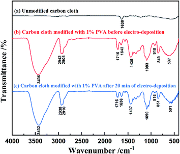 | ||
| Fig. 1 FTIR spectra of unmodified carbon cloth and modified carbon cloth before and after electro-deposition. | ||
In Fig. 1, the curves (a)–(c) represent the infrared spectra of unmodified carbon cloth, carbon cloth modified with 1% PVA before electro-deposition and after 20 min electro-deposition. There are many –OH, C–O, –CH2 and –CH groups in PVA. The absorption peaks at 3436 cm−1 on curve (b) are caused by the stretching vibration of –OH. The absorption peak at 1093 cm−1 is caused by the stretching vibration of C–O. The absorption peaks at 2905 cm−1 and 2942 cm−1 belong to the stretching vibration peak of –CH2. The absorption peak at 1435 cm−1 is related to the in-plane bending vibration of –CH, while the absorption peaks at 597 cm−1, 849 cm−1 and 918 cm−1 are related to the out of plane bending vibration of –CH. The absorption peaks at 1642 cm−1 and 1716 cm−1 are C![[double bond, length as m-dash]](https://www.rsc.org/images/entities/char_e001.gif) C and C
C and C![[double bond, length as m-dash]](https://www.rsc.org/images/entities/char_e001.gif) O respectively, which may be related to the carbon cloth substrate.
O respectively, which may be related to the carbon cloth substrate.
Comparing the curves (a) and (b) in Fig. 1, it could be found that the carbon cloth modified with PVA had –OH absorption peaks at 3436 cm−1, while the unmodified carbon cloth had almost no –OH absorption peak. Therefore, PVA was successfully modified on the surface of carbon cloth. At the same time, comparing the curves (a) and (c), it could be found that after 20 min electro-deposition, the absorption peaks of –CH, –OH, C–O and –CH2 groups could still be observed, indicating that PVA still existed on the electrode.
3.2 Analysis of deposit and the effect of PVA modification
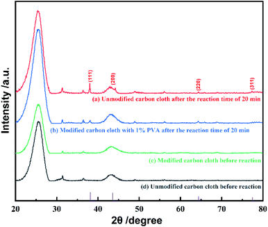
XRD characterization was performed on unmodified carbon cloth and PVA modified carbon cloth, before and after electro-deposition. The electro-deposition current density of 10 μA cm−2 and 1 mM silver nitrate was used. XRD results revealed that metal silver was successfully deposited on carbon cloth and the modification of PVA did have effects on crystal surface growth, as shown in Fig. 2. In Fig. 2, four typical diffraction peaks of metal silver are marked. Before deposition, as shown in curves (c) and (d) in Fig. 2, there is no new peaks in the XRD patterns, which indicates that there isn't diffraction peak for PVA. However, comparing the curves (b) and (c) in Fig. 2, it can be found that new diffraction peaks appear after electrochemical deposition on PVA modified carbon cloth, and the peaks indicate that the product crystallizes well with a structure that is in good agreement with metal silver (JCPDS No. 89-3722).As reported, the dominant crystal plane of silver nanoparticles is (111) because it has the highest thermodynamic stability.28 Many experiments show that during the nanoparticles' growth, the preferred growth plane is (111) crystal plane.26,27 This is also the case on unmodified carbon cloth as shown in curve (a) in Fig. 2. While the growth of (111) crystal plane is possibly limited on PVA modified carbon cloth in the electrochemical process, and other crystal planes become active and also grow, so as to form flower-like morphology.
3.3 Effect of PVA immersion concentration
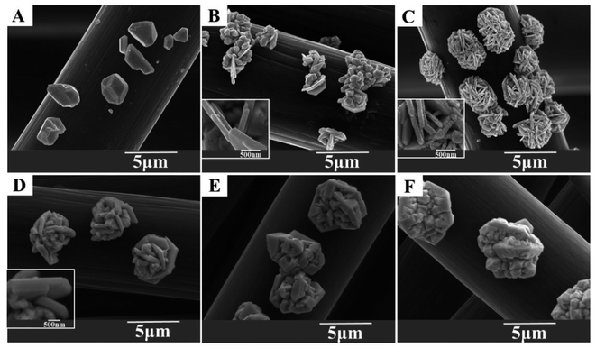
In order to investigate the effect of PVA amount, different concentrations of PVA were used to prepare modified carbon cloth cathode. Then the silver deposition was performed with these cathodes under the current density of 10 μA cm−2, silver nitrate concentration of 1 mM and reaction time of 20 min. The deposited silver particles were characterized by SEM and the results were shown in Fig. 3. After the reaction, on the unmodified carbon cloth electrode, the silver particles grow into a polyhedral block structure, and there is neither flake nor flower morphology, as shown in Fig. 3A. When PVA concentration is 0.5%, the particles are composed of blocks and flakes, as shown in Fig. 3B. The reason for this morphology may be that the immersion concentration is too low and has limited protection and inhibition on the crystal surface, so it is lumped and flaked but not layered, and at this time the thickness of the flake is about 120 nm, as the inset in Fig. 3B. Then the PVA concentration increases to 1%. The deposited silver is flower shaped with uniform size and clear petals. The petals thickness is about 100 nm, as shown in the inset of Fig. 3C. When PVA concentration further increased to 2%, the morphology keeps the similar flower shape but the petals thickness increased to about 380 nm as shown in Fig. 3D. When PVA concentration increased to 5% and 10%, the deposits changed from flower into block structure as shown in Fig. 3E and F. The particles size increased to micrometer scale significantly.Therefore, looking at the different morphological characteristics caused by changing the concentration of PVA, it can be found that if the concentration was too low, it would form a flake but not be layered. If the concentration was too high, it would form a block and the size was several micrometers. When the concentration of PVA was 1%, the deposited silver has uniform flower-like morphology, uniform size and petals thickness of 100 nm. The results indicated that a proper PVA concentration can help to obtain ideal flower-like Ag nanostructures.
3.4 Effect of current density
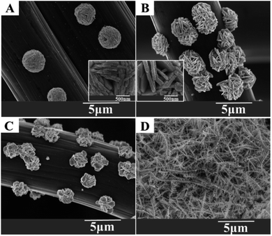
Current density is believed to have great impact on the morphology of nanoparticles.41 In order to investigate the effect of current density, silver particles were deposited under different current densities under a reaction time of 20 min on 1% PVA modified carbon cloth cathode and the obtained particles morphology were shown in Fig. 4. It can be found that under lower current densities, the flower-like nanostructures can be formed with the current density increases from 5–20 μA cm−2 (Fig. 4A–C). While under over high current density, the flower-like nanostructure can't be obtained (Fig. 4D). When the current density is 5 μA cm−2, the morphology of silver is flower-like shape which is composed of nanopetals with a thickness of about 100 nm, as shown in Fig. 4A and its inset. As the current increases to 10 μA cm−2, more obvious flower-like morphology with uniform size and clear petals can be seen in Fig. 4B. The petals structure is still clear with the increase of current density. But when the current density increases to 50 μA cm−2, the dendritic silver nanoparticles are interconnected to form a crisscross network morphology so that the flower-like nanostructure can't be obtained, as shown in Fig. 4D. This is possibly because the growth of silver crystals is dominated by the diffusion of silver ions, resulting in the formation of dendritic structure, which is in good agreement with the diffusion-limited aggregation (DLA) model.42,43The flower-like structure has two morphological characteristics of flakes and flowers at the same time. Through the above analysis, it was found that the deposited silver morphology changed from typical dendritic shape, and then to flower-like shape with the current density decrease. In order to obtain a uniform flower-like morphology, the optimized current density should be around 10 μA cm−2.
3.5 Effect of silver salt concentration
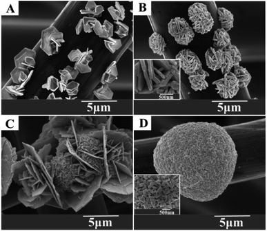
To verify the influence of the reaction and diffusion rate on the growth of silver particles and find out the proper initial silver ions concentrations for regulating flower-like silver, silver crystals were synthesized at various silver ions concentrations. At the current density of 10 μA cm−2, the morphology of silver particles changes from flower-like shape to spherical shape with the increase of silver concentration within 20 min, as shown in Fig. 5. At the concentration of 0.5 mM, the silver crystals present the morphological characteristics of flake and block growth on the cathode, as shown in Fig. 5A. The flake silver grows into hexagonal crystal, which is well in line with the crystal defect model, that is, the crystal defect theory of hexagonal seed evolving to flake structure.44 When silver concentration increased to 1 mM, the products are flower-like silver with uniform size, clear petals structure and petals thickness of about 100 nm, as shown in Fig. 5B. When the concentration further increased to 5 mM, the morphology of silver crystal is composed of flakes and small particles with flakes, as shown in Fig. 5C. When silver concentration further increased to 20 mM, the silver crystal presents a large spherical morphology. As shown in Fig. 5D and the inset, the spherical silver is composed of nano sized particles.It is known that reaction rate and diffusion rate are two interrelated factors regulating the growth of silver crystals. Different silver nitrate concentrations affect the concentration gradient on the growth front by affecting the supplement of silver ions to the surface of cathode, which can be understood by Mullins–Sekerka model.18,45 The reaction rate determines the consumption of reactive ions, while the diffusion rate determines the supplementation of these ions. The relative ratio of diffusion rate and reaction rate determines whether the concentration gradient could be formed and remained stable, which dictates the growth and development of flower-like silver nanostructures.41 At the same time, in order to regulate the flower-like structures with uniform size and clear petals structure, 1 mM silver nitrate concentration is an appropriate precursor concentration.
3.6 Effect of reaction time
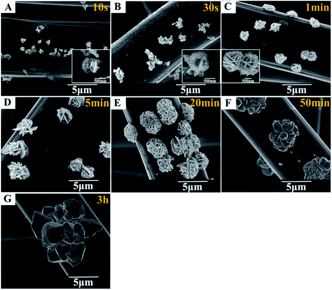
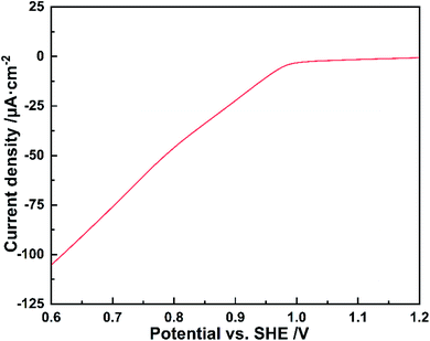
To disclose the formation process of flower-like silver nanostructures, we collect samples at various reaction times and characterize them by scanning electron microscopy, as shown in Fig. 6. Compared with various morphological characteristics from 10 s to 3 h, we can obviously observe the growth process of silver at the same scale. The overall situation can be summarized as follows: firstly, the spherical like nanostructure is formed by the stacked nanoparticles with a size of 50 nm (Fig. 6A), and then the nanoparticles grow and fuse into a single flake structure with a size of 100 nm (Fig. 6B and C), which is also the rudiment of flower-like structure, and then the number of flakes increases gradually. The preliminarily formed flower-like nanostructure can be seen in 5 min (Fig. 6D), and the structure will be completely formed in 20 min (Fig. 6E). Finally, with the reaction time extended to 50 min, the flaked silver will fuse and grow into blocks (Fig. 6F). Until the size of blocks reached 10 μm after 3 h reaction (Fig. 6G), the flower-like structures disappeared completely. In the reaction time of 20 min, the deposited silver has uniform morphology and size, which is an appropriate electrochemical synthesis parameter, as shown in Fig. 6E.In order to further understand the electro-deposition process of flower-like silver nanoparticles, linear sweep voltammetry was performed on 1% PVA modified carbon cloth in 0.1 mM silver nitrate solution. It can be found that the silver ions reduction start from 0.99 V vs. SHE from Fig. 7. The reduction current of 10 μA cm−2 (the optimal value for flower-like silver nanoparticles deposition) corresponds to the potential of ca. 0.95 V vs. SHE. This indicates that at relative positive potential and lower current density, the nuclei for flower-like silver nanoparticles can form and grow-up.
3.7 SERS activities
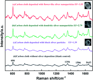
In order to evaluate the SERS performance of the flower-like nanostructured silver particles synthesized above, carbon cloth with different silver particles were tested as SERS substrates. Sample (a) was carbon cloth deposited with flower-like silver nano particles prepared by 1% PVA immersion, 10 μA cm−2 current density and 1 mM silver nitrate. Sample (b) was carbon cloth deposited with dendritic silver nano particles prepared by 1% PVA immersion, 20 μA cm−2 current density and 1 mM silver nitrate. Sample (c) was unmodified carbon cloth deposited with block silver particles prepared by 10 μA cm−2 current density and 1 mM silver nitrate. Sample (d) was 1% PVA modified carbon cloth without silver deposition as the blank control. The results were shown in Fig. 8.Sharp Raman characteristic peaks of Rhodamine 6G can be clearly observed in all curves. The peaks at 1356, 1506 and 1643 cm−1 are the stretching vibration peaks of the aromatic ring of Rhodamine 6G, and the peak at 606 cm−1 is in-plane deformation vibration of the ring.46 The enhancement factor (EF) of the SERS substrate with different silver particles can be roughly determined by the peak intensity ratio of sample to blank at 606 cm−1 according to the method reported.47 The carbon cloth deposited with flower-like nanostructured silver particles had the highest Raman scattering intensity which is 3.55 times of bare carbon cloth as blank. This is possibly resulted from the strong electromagnetic properties of petal-like protrusions in its nanostructure and the interdigitated nanosheets with many sharp nano edges and narrow gaps.39 Therefore, this highly anisotropic and layered silver nanostructure can significantly amplify the SERS signal. This intensity is also higher than carbon cloth with dendritic silver and block silver nanoparticles, which indicates the best SERS performance among these silver nanoparticles.
4. Conclusions
In this paper, the reaction conditions effect on flower-like silver nanoparticles were investigated. With 1% PVA modified carbon cloth as the cathode, at a current density of 10 μA cm−2, in 1 mM silver nitrate aqueous solution, after 20 min electro-deposition, the flower-like nano silver had high uniformity in morphology and size, and the petals thickness was about 100 nm. PVA plays a key role in control the crystal growth. The growth of petal structure may be attributed to the difference of surface energy of crystal planes, which may be regulated by PVA modified carbon cloth at the initial stage. As a result, after modifying carbon cloth with PVA, the morphology of silver crystal can be regulated by electrochemical method without adding additional morphology control agent. It is a new method to develop controllable synthetic materials in subsequent research.Author contributions
B.-A.: data curation; investigation; methodology; formal analysis; writing – original draft. W.-F.: funding acquisition; project administration; writing – review & editing. K.-B.: validation; visualization; formal analysis; methodology. J.-R.: data curation; methodology; validation. J.-Y.: formal analysis; writing – review & editing. Y.-H.: conceptualization; funding acquisition; project administration; supervision.Conflicts of interest
There are no conflicts to declare.Acknowledgements
This work was financially supported by Natural Science Foundation of China (No. 21878242), Fundamental Research Funds for the Central Universities of China (No. xpt022022014 and xzy012020025), Natural Science of Shaanxi Province of China (No. 2022JQ-087), and China Postdoctoral Science Foundation (No. 2020M673414).References
- V. Thomas, M. M. Yallapu, B. Sreedhar and S. K. Bajpai, J. Colloid Interface Sci., 2007, 315, 389–395 CrossRef CAS PubMed.
- J. Yong, Q. Wang, H. J. Ng, F. Malherbe and A. Yu, Nanosci. Nanotechnol. Lett., 2013, 5, 1293–1297 CrossRef CAS.
- S. Shoeibi and M. Mashreghi, J. Trace Elem. Med. Biol., 2017, 39, 135–139 CrossRef CAS PubMed.
- S. Yang, C. Cao, F. Wei, P. Huang, Y. Sun and W. Song, ChemCatChem, 2014, 6, 1868–1872 CrossRef CAS.
- M. Mahmoudi and V. Serpooshan, ACS Nano, 2012, 6, 2656–2664 CrossRef CAS PubMed.
- Y. Cho, S. Moon, C. Lee and Y. Lee, Appl. Surf. Sci., 2017, 394, 267–274 CrossRef CAS.
- R. Rooydell, S. Brahma, R. C. Wang, M. R. Modaberi, F. Ebrahimzadeh and C. P. Liu, J. Alloys Compd., 2017, 691, 936–945 CrossRef CAS.
- H. Ishitobi, T. Kobayashi, A. Ono and Y. Inouye, Opt. Commun., 2017, 387, 24–29 CrossRef CAS.
- Z. Dong, X. Le, Y. Liu, C. Dong and J. Ma, J. Mater. Chem. A, 2014, 2, 18775–18785 RSC.
- A. Nekahi, S. P. H. Marashi and D. H. Fatmesari, Mater. Chem. Phys., 2016, 184, 130–137 CrossRef CAS.
- W. Wang, Y. Zhong, D. Li, P. Wang, Y. Cai and Z. Duan, J. Electron. Mater., 2015, 44, 4920–4927 CrossRef CAS.
- B. Chen, X. Jiao and D. Chen, Cryst. Growth Des., 2010, 10, 3378–3386 CrossRef CAS.
- R. D. Glover, J. M. Miller and J. E. Hutchison, ACS Nano, 2011, 5, 8950–8957 CrossRef CAS PubMed.
- M. Luo, H. Huang, S. Choi, C. Zhang, R. Silva, H. Peng, Z. Li, J. Liu, Z. He and Y. Xia, ACS Nano, 2015, 9, 10523–10532 CrossRef CAS PubMed.
- R. De, Y. Shin, C. Lee and M. Oh, Appl. Spectrosc., 2016, 70, 1137–1149 CrossRef CAS PubMed.
- Y. Zheng, J. Zeng, A. Ruditskiy, M. Liu and Y. Xia, Chem. Mater., 2014, 26, 22–33 CrossRef CAS.
- Y. Wang, D. Wan, S. Xie, X. Xia, C. Huang and Y. Xia, ACS Nano, 2013, 7, 4586–4594 CrossRef CAS PubMed.
- C. Gu and T. Zhang, Langmuir, 2008, 24, 12010–12016 CrossRef CAS PubMed.
- C. Regan, X. Zhu, J. Zhong, U. Anand, J. Lu, H. Su and U. Mirsaidov, Langmuir, 2016, 32, 3601–3607 CrossRef PubMed.
- W. M. Schuette and W. E. Buhro, ACS Nano, 2013, 7, 3844–3853 CrossRef CAS PubMed.
- A. Katsuki, I. Uechi, M. Fujiwara and Y. Tanimoto, J. Cheminf., 2003, 34, 275–279 Search PubMed.
- J. Xiao, Y. Xie, R. Tang, M. Chen and X. Tian, Adv. Mater., 2001, 13, 1887–1891 CrossRef CAS.
- S. Zhou, J. Li, K. Gilroy, J. Tao and Y. Xia, ACS Nano, 2016, 10, 9861–9870 CrossRef CAS PubMed.
- K. Tsai, K. Sivashanmugan, C. Lin, P. Tsai, S. Cheng, Y. Lan, T. Chen and T. Wen, J. Taiwan Inst. Chem. Eng., 2016, 69, 146–150 CrossRef CAS.
- R. A. Khaydarov, R. R. Khaydarov, O. Gapurova, Y. Estrin and T. Scheper, J. Nanoparticle Res., 2009, 11, 1193–1200 CrossRef CAS.
- D. K. Sharma, A. Ott, A. P. Mullane and S. K. Bhargava, Colloids Surf., A, 2011, 386, 98–106 CrossRef CAS.
- S. Cherevko, X. Xing and C. Chung, Electrochem. Commun., 2010, 12, 467–470 CrossRef CAS.
- M. Mazur, Electrochem. Commun., 2004, 6, 400–403 CrossRef CAS.
- G. A. Molina, R. Esparza, J. L. Lopez-Miranda, A. R. Hernandez-Martinez, B. L. Espana-Sanchez, E. A. Elizalde-Pena and M. Estevez, Colloids Surf., B, 2019, 180, 141–149 CrossRef CAS PubMed.
- H. Zheng, D. Ni, Z. Yu, P. Liang and H. Chen, Sens. Actuators, B, 2016, 231, 423–430 CrossRef CAS.
- C. Zhang, R. Hao, B. Zhao, Y. Fu, Y. Hao and Y. Liu, J. Mater. Sci., 2017, 52(19), 11391–11401 CrossRef CAS.
- M. Xu and Y. Zhang, Appl. Surf. Sci., 2017, 393, 197–203 CrossRef CAS.
- H. Tang, P. Zheng, G. Meng, Z. Li, C. Zhu, F. Han, Y. Ke, Z. Wang, F. Zhou and N. Wu, Nanotechnology, 2016, 27(32), 325303 CrossRef.
- B. Wulan, L. Zhao, D. Tan, X. Cao, J. Ma and J. Zhang, Adv. Energy Mater., 2022, 12(19), 2103960 CrossRef CAS.
- L. Vitos, A. V. Ruban, H. L. Skriver and J. Kollár, Surf. Sci., 1998, 411, 186–202 CrossRef CAS.
- S. Guo, Y. Chao, H. Yang, Y. Yang, Y. Li and W. Fang, Chin. J. Inorg. Chem., 2018, 34, 421–426 CAS.
- R. Ma, B. Kang, S. Cho, M. Choi and S. Bai, ACS Nano, 2015, 9(11), 10876–10886 CrossRef CAS PubMed.
- Y. H. Chang, C. Liu, S. Rouvimov, T. Luo and S. P. Feng, Chem. Commun., 2017, 53(50), 6752–6755 RSC.
- L. Cheng, C. Ma and G. Yang, J. Mater. Chem. A, 2014, 2(13), 4534–4542 RSC.
- L. Hong, Q. Li, H. Lin and Y. Li, Mater. Res. Bull., 2009, 44, 1201–1204 CrossRef CAS.
- T. Yang, W. Liu, P. Che, C. Li and Y. Han, CrystEngComm, 2015, 17, 6014–6022 RSC.
- W. Cai, Y. Wang, K. Pu and Q. Ma, J. Exp. Nanosci., 2017, 12, 1–19 CrossRef.
- Y. Wang, B. Wang, B. Pan, Q. Chen and W. Yan, Appl. Energy, 2013, 112, 1337–1341 CrossRef CAS.
- D. Aherne, D. M. Ledwith, M. Gara and J. M. Kelly, Adv. Funct. Mater., 2008, 18, 2005–2016 CrossRef CAS.
- S. Xie, X. Zhang, D. Xiao, M. C. Paau, J. Huang and M. M. F. Choi, J. Phys. Chem. C, 2011, 115, 9943–9951 CrossRef CAS.
- B. Zhang, A.-W. Zhao, D.-P. Wang, H.-Y. Guo, D. Li and M. Li, Chem. J. Chin. Univ., 2010, 31(8), 1491–1495 CAS.
- D. Deng, Q. Lin, H. Li, Z. Huang, Y. Kuang, H. Chen and J. Kong, Talanta, 2019, 200, 272–278 CrossRef CAS PubMed.
| This journal is © The Royal Society of Chemistry 2022 |

