 Open Access Article
Polyimide-derived carbon nanofiber membranes as free-standing anodes for lithium-ion batteries
Hang Xua,
Chuanqiang Yina,
Xinran Houa,
Man Gonga,
Changshu Yanga,
Lexiang Xua,
Jinpeng Luoa,
Lei Mab,
Lang Zhoua and
Xiaomin Li *a
*a
aInstitute of Photovoltaics, Nanchang University, Nanchang 330031, PR China. E-mail: lixiaomin@ncu.edu.cn; Fax: +86-791-83969329; Tel: +86-791-83969329
bGuangxi Key Laboratory of Information Materials, Guilin University of Electronic Technology, Guilin 541004, P. R. China
First published on 9th August 2022
Abstract
Free-standing and flexible carbon nanofiber membranes (CNMs) with a three-dimensional network structure were fabricated based on PMDA/ODA polyimide by combining electrospinning, imidization, and carbonization strategies. The influence of carbonization temperature on the physical-chemical characteristics of CNMs was investigated in detail. The electrochemical performances of CNMs as free-standing electrodes without any binder or conducting materials for lithium-ion batteries were also discussed. Furthermore, the surface state and internal carbon structure had an important effect on the nitrogen state, electrical conductivity, and wettability of CNMs, and then further affected the electrochemical performances. The CNMs/Li metal half-cells exhibited a satisfying charge–discharge cycle performance and excellent rate performance. They showed that the reversible specific capacity of CNMs carbonized at 700 °C could reach as high as 430 mA h g−1 at 50 mA g−1, and the value of the specific capacity remained at 206 mA h g−1 after 500 cycles at a high current density of 1 A g−1. Overall, the newly developed carbon nanofiber membranes will be a promising candidate for flexible electrodes used in high-power lithium-ion batteries, supercapacitors and sodium-ion batteries.
1. Introduction
With the ever-growing demands for flexible electronic devices such as in roll-up displays and wearable devices, flexible energy storage devices with high energy and cycle stability have gained dramatic attention in recent years.1–4 Flexible lithium-ion batteries (LIBs) are expected to be the most promising candidates as the energy storage system due to their high energy density, long charge and discharge life, no memory effect, and low environmental pollution.5–7 The energy density of the flexible LIBs depends mainly on the electrode materials, especially the anode materials.8 Therefore, developing anode materials with excellent comprehensive performances has become the most important issue for flexible LIBs. Traditional anode materials, such as silicon-based materials,9–12 tin-based materials13 and new alloys,14 have difficulty meeting the widely commercial applications of flexible LIBs due to high costs, complex preparation processes, more side reactions and large volume expansion,15–19 whereas, carbon materials are widely used as anode materials for flexible energy storage because of their high performance, low cost, and designability of structures.20,21 Among various forms of carbon materials, carbon nanofiber membranes are most suitable for flexible LIBs as the anode materials, thanks to their high porosity, high specific surface area, self-supporting properties, and designability. Therefore, developing self-standing carbon nanofiber electrodes will be a promising strategy for flexible LIBs.22,23Electrospinning technique is a simple and cost-effective method for fabricating nanofibers and flexible nanofiber membranes with wide range of fiber diameters,24–27 which shows great application potential in the field of flexible energy storage. Usually, the electrospinning nanofiber membranes cannot be directly applied to electrode materials because of the poor conductivity of most electrospinning precursors. In terms of the electrospinning precursors for CNMs, high carbon yield and excellent spinnability are the prime factors to be considered. In previous studies, the raw materials of electrospinning CNMs have rich resources, such as polyacrylonitrile (PAN),28–30 pitch,31 polyvinylpyrrolidone (PVP),32 polyimide (PI),33 and so on. Typically, PAN is the most commonly used material as carbon precursor due to its relatively low cost, high elastic modulus and high carbon residue rate.34 However, the manufacturing process of PAN is complicated, since it involves many steps, such as polymerization, precursor preparation, pre-oxidation, oxidation, carbonization, etc., which must be carefully controlled and optimized.35–37
Polyimide (PI), as a kind of high-performance engineering polymers, has many advantages as carbon precursors, such as high carbon yield, high mechanical strength, molecular design diversity, strong viscosity adjustability, and so on.38–40 Nan et al.34 successfully prepared porous carbon nanofibers (PCNFs) with electrospinning polyimide and SiO2 as self-standing anodes of LIBs by carbonization and post-etching. The PCNFs exhibited interconnected nanofibrous morphology with large specific surface area (950 m2 g−1) and outstanding electrochemical performance. Han et al.41 reported polyimide-derived carbon nanofibers for self-standing supercapacitor electrode materials, which were fabricated by electrospinning, imidization, and carbonization process. Therefore, PI can be used as a promising candidate as carbon precursor for preparing high-performance self-supporting flexible electrode materials. Generally, the imidization process and carbonization process are carried out step by step in air and Ar atmosphere, respectively. The thermal treatment of rising and falling temperature twice not only increases the energy consumption but also increases the complexity of material preparation process, which hinders industrial applications. It is well-known that the activation energy (Ea) of polymer decomposition under vacuum condition is higher than that under inert atmosphere condition. Therefore, it can be predicted that carbon fiber membranes can be more fully tarred by vacuum pyrolysis at the same temperature. That is, high quality membranes can be obtained under vacuum conditions at lower temperature. As far as we know, there has been rarely reported on the systematic studies about comprehensive properties of CNMs anode materials for flexible LIBs derived from PI as carbon matrix precursor.
In this work, a series of free-standing CNMs electrode materials have been reported comprehensively, which are derived from PI via electrospinning and subsequent imidization and carbonization process simultaneously under high vacuum conditions. The traditionally inexpensive monomers, such as pyromellitic dianhydride (PMDA) and the 4.4′-diaminodiphenyl ether (ODA), were used as the dianhydride and diamine monomers, respectively. The as-prepared free-standing CNMs were directly used as anodes in LIBs without any binder and conductive additive due to structural integrity and good electrical conductivity. Furthermore, the influences of pyrolysis temperature on the basic physical and electrochemical performance of CNMs were investigated in detail as the anode material for flexible LIBs.
2. Experimental
2.1 Materials
Pyromellitic dianhydride (PMDA, ≥99.5%) was provided by Tianjin Haopu Chemical Co., Ltd, and dried in vacuum at 150 °C for 2 h before use. 4.4′-Diaminodiphenyl ether (ODA, ≥99.5%) was supplied by Wanda Chemical Co., Ltd and used without further purification. N,N-Dimethylacetamide (DMAc, AR) was purchased from Sinopharm Chemical Reagent Co., Ltd and purified using 4A molecular sieves.2.2 Sample preparation
![[thin space (1/6-em)]](https://www.rsc.org/images/entities/char_2009.gif) :
:![[thin space (1/6-em)]](https://www.rsc.org/images/entities/char_2009.gif) 1.01 (molar ratio) with a nitrogen inlet and mechanical stirring. The light yellow viscous PAA solution with a solid content of 10 wt% was obtained after mechanical stirring for 5 hours. Subsequently, the PAA solution was diluted with 25 g of DMAc and the kinematic viscosity measured by the rotary viscometer (NDJ-4S, Shanghai Pingxuan Scientific Instrument Co., Ltd.) was 62251 mPa s. The PAANMs were prepared by the electrospinning with a single syringe as the electrospinning nozzle. The appropriate parameters were mainly determined by the concentration and properties of electrospinning solution. In this experiment, the optimum parameters were set with the spinning speed of l mL h−1, spinning voltage of 15 kV and distance between the spinneret and the collection drum of 15 cm.
1.01 (molar ratio) with a nitrogen inlet and mechanical stirring. The light yellow viscous PAA solution with a solid content of 10 wt% was obtained after mechanical stirring for 5 hours. Subsequently, the PAA solution was diluted with 25 g of DMAc and the kinematic viscosity measured by the rotary viscometer (NDJ-4S, Shanghai Pingxuan Scientific Instrument Co., Ltd.) was 62251 mPa s. The PAANMs were prepared by the electrospinning with a single syringe as the electrospinning nozzle. The appropriate parameters were mainly determined by the concentration and properties of electrospinning solution. In this experiment, the optimum parameters were set with the spinning speed of l mL h−1, spinning voltage of 15 kV and distance between the spinneret and the collection drum of 15 cm.
2.3 The physical–chemical characteristics of CNMs
The pyrolysis behavior of PAANMs was carried out by a thermo gravimetric analyzer (TGA, STA 2500, NETZSCH, Germany) in flowing nitrogen at a heating rate of 10 °C min−1 from 30 to 1200 °C. The pyrolysis gases of PI nanofiber membranes (PINMs) derived from PAANMs were identified by a thermal mass spectrometry analyzer (Thermo Mass Photo, Rigaku, Japan) under He atmosphere at a heating rate of 10 °C min−1. The microscopic morphologies of CNMs were characterized by a scanning electron microscope (SEM, phenom pharos-type, Phenom-World, Netherlands). The crystalline structures of CNMs were evaluated by an X-ray diffractometer (XRD, D8 ADVANCE, Bruker, Germany) and Raman spectrometer (XploRA, Horiba Jobin-Yvon, France). The variations of element state in the electrodes were investigated using X-ray photoelectron energy spectra (XPS, ESCALAB 250Xi, Thermo Fisher Scientific, America). The electric conductivity test was carried out in a precision four-probe resistivity tester (HPS2662, China). Contact angle measuring instrument (WAM-100, China) was employed to identify the wettability of CMNs.2.4 Assembling and electrochemical characterization of LIBs
CR2025 coin cells were assembled with 1 M LiPF6/EC:DMC electrolyte by the as-obtained CNMs as anodes, the Li metal as counter electrodes and commercial PE as separators in a glove box filled with an argon atmosphere and the contents of water and oxygen lower than 0.5 ppm. To evaluate the electrochemical performances, the cycling and rate performances were carried out on a battery cycler (Neware CT-4008, China). The electrochemical impedance spectroscopy (EIS) and cyclic voltammetry (CV) were performed by Princeton Applied Research spectrometer (Versa STAT 3, America). The frequency range of EIS test is from 0.01 to 100![[thin space (1/6-em)]](https://www.rsc.org/images/entities/char_2009.gif) 000 Hz and the voltage range adopted in the CV test is from 1.5 V to 0.01 V.
000 Hz and the voltage range adopted in the CV test is from 1.5 V to 0.01 V.
3. Results and discussion
3.1 Macrostructure and microstructure of the as-obtained CNMs
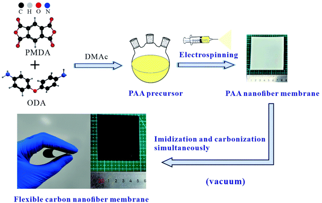
The macrostructures of the membranes before and after imidization-carbonization treatment are in Fig. 1, corresponding to PAANMs and CNMs, respectively. It is found that the color of PAANMs prepared by electrospinning changed significantly during imidization and carbonization. PAANMs are white silk-like membranes, which are transformed into smooth and flexible carbon membranes after imidization-carbonization treatment, indicating a potential application in the fields of flexible LIBs, etc.Fig. 2 shows the morphology of the as-obtained CNMs characterized by SEM, along with PAANMs as a reference. The carbon nanofibers have relatively smooth and cylindrical shapes. The average diameter of the nanofibers gradually decreases with the increase of temperature. Combined with literature reported, the PI molecular chain shrinks during imidization and carbonization.41,42 Element decomposition and solvent volatilization also occur in the heating process, which jointly reduce the diameter of the fibers.
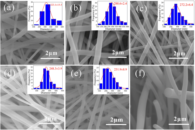 | ||
| Fig. 2 SEM images of (a) PAANMs, (b) CNMs-500, (c) CNMs-700, (d) CNMs-900, (e) CNMs-1200 and (f) cross-section SEM image of CNMs-700. | ||
3.2 The pyrolysis behavior of the as-obtained PAANMs
The TGA curve of the as-obtained PAANMs under nitrogen atmosphere is shown in Fig. 3a, which exhibits multiple-step weight losses from 30 to 1000 °C. It is obvious that the curve can basically be divided into three processes. The first stage is related to the removal of residual water molecules and volatilization of solvent during the imidization reaction, which leads to the chemical transformation from PAA to PI before 250 °C. Secondly, a platform appeared before 500 °C, and the curve did not change significantly with low weight loss, indicating that PINMs had excellent thermal stability. The third weight loss is associated with the carbonization of PINMs after 550 °C. It dropped sharply in a relatively narrow temperature range (550–700 °C), and the mass loss was also obvious with the value of 27.69%, indicating that a violent decomposition reaction happened during this stage. Accordingly, the structure and performances of the sample would also change. The decomposition reaction of PI during the 700–1000 °C becomes gentle with small weight loss, indicating that the reformation of the carbon structure mainly occurs, and the thermal polycondensation reaction occupies the main position. The whole weight loss of PAANMs is close to 70% by calculation.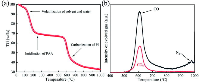 | ||
| Fig. 3 (a) TGA curve of PAANMs under nitrogen atmosphere at a heating rate of 10 °C min−1. (b) Thermal mass spectrometry of PINMs under He atmosphere at a heating rate of 10 °C min−1. | ||
With the decomposition of PINMs at different heat treatment stages, different kinds of gases gradually release, such as CO, CO2, N2, H2, CH4, etc.43 The evolved CO, CO2, N2 gases of PINMs in the heat treatment process were analyzed under He atmosphere, as shown in Fig. 3b. Before 500 °C, the amounts of released CO, CO2, and N2 released were so little that can be ignored. With the temperature rising, the emissions of CO and CO2 gas increased sharply, reaching the maximum value at 600 °C, and then gradually decreased, which is consistent with the weight loss in Fig. 3a. As the temperature continued to rise, the proportion of N2 escaping was dominant. It demonstrated that the imine ring underwent partial ring-opening reaction and C![[double bond, length as m-dash]](https://www.rsc.org/images/entities/char_e001.gif) O and C–O in the main chain broke, resulting in the precipitation of small molecule gases such as CO2 and CO. After 700 °C, the reaction of pyrolysis to form CO2 was basically over while the removal of heteroatoms continues, accompanied by the escape of N2.
O and C–O in the main chain broke, resulting in the precipitation of small molecule gases such as CO2 and CO. After 700 °C, the reaction of pyrolysis to form CO2 was basically over while the removal of heteroatoms continues, accompanied by the escape of N2.
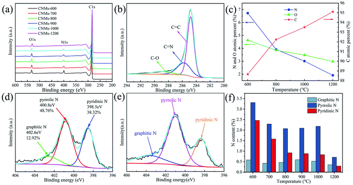
To further investigate the surface compositions of the CNMs and the bonding configurations of the N atoms, XPS measurements were performed (Fig. 4). The spectrum shows strong signals of C, N, O (Fig. 4a). In the C1s spectrum (Fig. 4b), the sharp peak near 284.8 eV corresponds to the sp2 carbon with a C![[double bond, length as m-dash]](https://www.rsc.org/images/entities/char_e001.gif) C bond. The sp2 carbon with a C
C bond. The sp2 carbon with a C![[double bond, length as m-dash]](https://www.rsc.org/images/entities/char_e001.gif) N bond shows a second weak peak at 285.8 eV. The third small peak near 289 eV is attributed to the sp3 carbon.44 It is well known that the atomic radius of the N is close to that of the C and the electronegativity of the N (3.04) is higher than that of the C (2.55). Therefore, the increase of nitrogen content is beneficial to the electrochemical performance. With the increase of carbonization temperature, the polyimide fiber membrane keeps releasing small molecule gases, such as CO, CO2 and N2, along with the breakage of C–O, C–N bonds and the formation of C–C. The content of C keeps increasing while the content of N and O keeps decreasing (Fig. 4c). Nitrogen bonding configurations and content were displayed in Fig. 4d and e. The amounts of graphitic-N (402.6 eV), pyrrolic-N (400.8 eV) and pyridinic-N (398.5 eV) in CNMs prepared at 700 °C are 12.92%, 48.76% and 38.32%, respectively. In contrast, the graphitic-N percentage of CNMs-900 is 16.43% relatively, indicating that CNMs-900 has a higher degree of graphitization than that of CNMs-700. Fig. 4f shows the ratios of different types of N for various samples. It suggests that the heteroatoms of nitrogen are gradually eliminated at high temperature, and the content of N gradually decreases with increasing temperature.
N bond shows a second weak peak at 285.8 eV. The third small peak near 289 eV is attributed to the sp3 carbon.44 It is well known that the atomic radius of the N is close to that of the C and the electronegativity of the N (3.04) is higher than that of the C (2.55). Therefore, the increase of nitrogen content is beneficial to the electrochemical performance. With the increase of carbonization temperature, the polyimide fiber membrane keeps releasing small molecule gases, such as CO, CO2 and N2, along with the breakage of C–O, C–N bonds and the formation of C–C. The content of C keeps increasing while the content of N and O keeps decreasing (Fig. 4c). Nitrogen bonding configurations and content were displayed in Fig. 4d and e. The amounts of graphitic-N (402.6 eV), pyrrolic-N (400.8 eV) and pyridinic-N (398.5 eV) in CNMs prepared at 700 °C are 12.92%, 48.76% and 38.32%, respectively. In contrast, the graphitic-N percentage of CNMs-900 is 16.43% relatively, indicating that CNMs-900 has a higher degree of graphitization than that of CNMs-700. Fig. 4f shows the ratios of different types of N for various samples. It suggests that the heteroatoms of nitrogen are gradually eliminated at high temperature, and the content of N gradually decreases with increasing temperature.
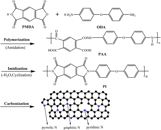
Based on the above discussion, the formation mechanism of CNMs can be described in Fig. 5. Firstly, PMDA and ODA undergo polymerization reaction to synthesize PAA. Secondly, PAA converts to PI with dehydration cyclization by imidization reaction. Finally, PI turns into free-standing and flexible CNMs through carbonization where the heterocycles were combined. The residual nitrogen and oxygen were removed to form a continuous huge aromatic heterocyclic compound. Meanwhile, there are three nitrogen compositions, including graphite-N, pyridine-N and pyrrole-N. Besides, the proportion of pyridinic-N and pyrrolic-N is higher than that of graphite nitrogen (Fig. 4f). When the temperature rises continuously, graphite-like hexagonal carbon network layer gradually grows. It can be explained that the C–O and C–N bonds are continuously broken, and the C–C bonds are continuously formed during the carbonization. At the same time, small molecular gases, such as CO, CO2 and N2, are released as shown in Fig. 3b, resulting in large weight loss of PINMs shown in Fig. 3a. According to the literature,45–47 the size of PINMs will be greatly reduced when carbonized at 600–1000 °C. The graphite-like structure is gradually derived at 700 °C, and the electrical properties of the materials have a turning point at 700 °C. Hereby, from the above analysis, carbonization temperature is a key parameter that affects the structure of CNMs.
3.3 Microcrystalline structure of the as-obtained CNMs
Fig. 6a is the X-ray diffraction (XRD) patterns of CNMs at different carbonization temperatures to characterize the crystalline features. As seen in Fig. 6a, broad (002) diffraction peaks at about 23° and weak (100) diffraction peaks at 44° are present in the XRD patterns of CNMs, which are typical amorphous graphite structures. With the increase of carbonization temperature, the 2θ angle moved toward the high angle direction and the peak strength increased gradually. CNMs-500 showed a steamed bread-like and weak diffraction peak at 19.32°, indicating that CNMs-500 was poorly crystalline. According to literature reports,48 the 2θ angle corresponding to the dispersion peak of the 19–25° interval is caused by the coherent scattering among molecular chains. The PI prepared by the thermal imidization process only formed a certain ordered structure, and the ordered aggregation phase in PINMs was mainly formed by the arrangement of the molecular chains.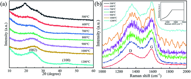 | ||
| Fig. 6 (a) X-ray diffraction patterns, (b) Raman spectrum of CNMs at different carbonization temperatures. | ||
The Raman spectrum characteristics and structural changes of CNMs at different carbonization temperatures are investigated as shown in Fig. 6b. The Raman spectrum is taken from samples prepared at temperatures ranging from 500 to 1200 °C. Obviously, there are D (Disorder) band and G (Graphite) band near 1355 cm−1 and 1575 cm−1, respectively, except for the CNMs-500. Because of the inactive groups and insufficient heat treatment, CNMs-500 is hard to form carbon peaks in the Raman spectrum. The intensity of D band characterizes the disordered non-graphitization structure. The G band is regarded as the sp2 stretching vibration peak of C–C bond, which originates from the optical transition of crystalline graphite. It is well known that G band is caused by ordered graphite carbon structure, while D band is related to the defects in carbon materials. As some researchers49,50 pointed out, all carbon materials except graphite single crystals exhibit two Raman scattering peaks around 1355 cm−1 and 1575 cm−1 originating from aromatic ring vibrations, which is also confirmed in our experiments. Usually, the intensity ratio of D and G band (ID/IG) was evaluated for comparison. The relative intensity ratio R of D band to G band is:
| Carbonization temperature/°C | R = ID/IG |
|---|---|
| 600 | 1.5963 |
| 700 | 1.5835 |
| 800 | 1.1753 |
| 900 | 0.9122 |
| 1000 | 0.8840 |
| 1200 | 0.6637 |
3.4 Electrical conductivity and wettability of the as-obtained CNMs
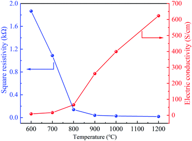
Fig. 7 shows that the square resistance gradually decreases but electrical conductivity increases from 600 to 1200 °C. With the increase of temperature, the structure of CNMs gradually tends to be regular and changes from an amorphous anisotropic state to a hexagonal carbon layer structure. Meanwhile, stable unpaired electrons were generated from the pyrolysis, forming continuous dense ring carbon network (Fig. 5).30 As shown in the previous XPS results, the increase of graphite crystallite and carbon content is beneficial to improve electrical conductivity.In order to investigate the effects of the carbonization temperature on the wettability of the CNMs, contact angle measurements with water droplets were carried out. As shown in Fig. 8, the angles of CNMs-600, CNMs-700, CNMs-800, CNMs-900, CNMs-1000 and CNMs-1200 are 15.58, 23.03, 33.62, 39.43, 48.71 and 58.07°, respectively, which implicate that CNMs possess hydrophilic surface. The increasing contact angle implies that the CNMs-700 has a better wettability compared to the CNMs-800. Since the bond energy of C–N is higher than that of C–C, the N atoms improve the surface energy of carbon materials. The higher the N content, the better the wettability.44
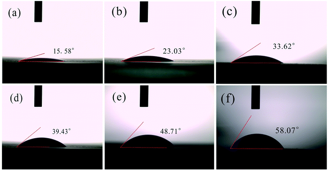 | ||
| Fig. 8 Contact angle determination for (a) CNMs-600, (b) CNMs-700, (c) CNMs-800(d) CNMs-900, (e) CNMs-1000, (f) CNMs-1200. | ||
| Samples | Rs (Ω) | Rct (Ω) |
|---|---|---|
| CNMs-600 | 2.625 | 709.5 |
| CNMs-700 | 4.904 | 407.5 |
| CNMs-800 | 3.412 | 362.3 |
| CNMs-900 | 2.448 | 214.8 |
| CNMs-1000 | 5.132 | 160.0 |
| CNMs-1200 | 6.313 | 151.4 |
3.5 Electrochemical performances of the CNMs/Li cell
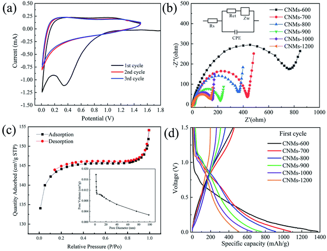
To further understand the mechanisms and the detailed reaction kinetics, the electrochemical behavior of CNMs was further investigated by CV test. Fig. 9a shows the CV curves of CNMs-700 in the first three cycles. In the first cycle, when the voltage reaches between 0.2 and 0.5 V, a significant and wide hump appears on the cathode curve, which is related to the formation of the SEI film on the electrode surface and the decomposition reaction of the electrolyte.51 In addition, two oxidation peaks appear at voltages of 0.1 V and 1.2 V, respectively, which are associated with the gradual insertion of Li+ to the unsaturated C![[double bond, length as m-dash]](https://www.rsc.org/images/entities/char_e001.gif) C on benzene rings.52 During the subsequent charge/discharge cycles, the CV curves largely overlapped each other, demonstrating the excellent cycling stability of the CNMs electrodes.
C on benzene rings.52 During the subsequent charge/discharge cycles, the CV curves largely overlapped each other, demonstrating the excellent cycling stability of the CNMs electrodes.
To further demonstrate the effects of temperature on the fast charge transfer kinetics of electrodes, the electrochemical impedance spectroscopy (EIS) analysis was further performed, as shown in Fig. 9b. Before cycling, there are semicircle arc-shaped curves representing the charge-transfer resistance (Rct) on electrode/electrolyte interface53,54 and an inclined low-frequency line (Table 2). Obviously, the CNMs-600 has the largest semicircle due to the large charge transfer resistance and failure to provide abundant charge transfer channels on electrode/electrolyte interface. The semicircle of CNMs-1200 is much smaller than that of CNMs-700 because of the faster electrochemical reaction kinetics, indicating that the increase of carbonization temperature improves electrical conductivity to a certain extent, which is consistent with the results of Fig. 6.
To characterize the porous of CNMs, Fig. 9c shows the N2 adsorption and desorption curves and pore size distribution curves. The BET surface area of the CNMs-700 was calculated to be 438.97 m2 g−1, and the total pore volume was 0.2 cm3 g−1, indicating that the fibers have a rich pore structure and high specific surface area. This provides abundant energy storage sites for achieving better electrochemical performance, which is beneficial to improve the storage capacity of lithium ions. For porous carbon anode materials, making full use of the large specific surface area to enhance the capacity and multiplicity performance while improving the initial coulomb efficiency is a worthy study, but also a more difficult problem.55 Fig. 9d shows the charge/discharge curves of CNMs electrodes in the voltage range of 0–1.5 V at a current density of 25 mA g−1. In general, all charge/discharge curves show steep slopes and insignificant plateaus, which correspond to the insertion of lithium ions between graphene layers and into nanopores.56,57 The first discharge and charge capacity of CNMs-700 can reach 1078 mA h g−1 and 458 mA h g−1, corresponding to a coulomb efficiency of 42%. The remaining loss is mainly due to the formation of SEI film.
The multiplicative performance of CNMs electrodes was investigated by testing at different current densities (Fig. 10a). CNMs-700 exhibited best multiplicative properties than other CNMs electrodes. At 0.05, 0.1, 0.2, 0.5 and 1 A g−1, the reversible capacities of CNMs-700 can reach 430, 315, 280, 269, 241 and 203 mA h g−1, respectively, which can be mainly contributed to higher N content and better wettability as shown in the test of contact angle and XPS. It was reported47 that N can not only change the electronic state of the carbon surface and improve electrical conductivity of the materials, but also bring in defects to increase the binding points between the surface of the carbon material and the lithium ions, thereby enhancing the performance of lithium storage. To further investigate the stability of multiple charge/discharge cycles of the CNMs electrodes at high current density, tests were conducted at a current density of 1 A g−1. As shown in the Fig. 10b, the reversible embedded lithium capacity of the CNMs-700 can reach 206 mA h g−1 after 500 cycles, demonstrating good cycling stability. However, CNMs-500 has no capacity display as the anode, because the heat treatment temperature was too low to achieve sufficient graphitization and form effective conductive carbon layer structure. CNMs-600 has the highest initial discharge capacity, but its cycling performance is the lowest due to the insufficient carbonization and the formation of unstable SEI membrane during cycling. High electrical conductivity of materials contributes to charge transfer when they are employed as anode in LIBs. Although electrical conductivity of the material increased gradually, the N content and the position of N defect decreased gradually. Therefore, as the temperature increases, the discharge specific capacity of CNMs electrodes gradually decreases and the capacity of CNMs-1200 was relatively lower with the value of 142 mA h g−1. Notably, when the current density increases to 1 A g−1, CNMs-900 exhibits better capacity (184 mA h g−1) at high current density than CNMs-800 (172 mA h g−1), indicating that the high electrical conductivity and low impedance contribute to better rate performance, which is also further evidenced by Fig. 7 and 9b. To evaluate the structural stability of the CNMs electrodes, the macroscopic and microscopic morphology of CNMs-700 after 500 cycles at a high current density of 1 A g−1 was investigated. As shown in Fig. 10c, there are almost no cracks on the surface of the electrode, which can still maintain a good independent structure without major damage to the overall macroscopic morphology, indicating that this self-supporting three-dimensional network structure can well suppress the changes in the electrode structure after cycling. Obviously, SEM image (Fig. 10d) shows that the surface of CNMs-700 becomes rough compared to the initial nanofibers. The fibers are covered with a layer of small granular material after cycling, which is related to the reaction of the electrode with the electrolyte to form a stable SEI film on the surface. Thus, after the complex reaction with the electrolyte, the fibers are still able to maintain a good freestanding structure.
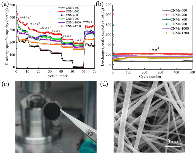 | ||
| Fig. 10 (a) Rate performance, (b) cycling performance for various samples at different carbonization temperatures, (c) photograph, (d) SEM image of CNMs-700 after 500 cycles. | ||
4. Conclusions
In summary, polyimide-derived carbon nanofiber membranes with three-dimension structure were successfully prepared by the simple electrospinning and imidization-carbonization strategy, which can be directly used as the free-standing anode electrode for flexible LIBs. The results show that the carbonization temperature is one of the crucial factors that affect the N content, surface wettability, electrical conductivity, which further influence the electrochemical performances of LIBs. The flexible free-standing CNMs-700 exhibits excellent cycling stability and rate capability with 430 mA h g−1 reversible specific capacity at 0.05 A g−1 and a retain value of 206 mA h g−1 after 500 cycles at 1 A g−1. Consequently, considering comprehensively flexibility, energy density, low cost, simple synthesis and excellent performance, CNMs could be a promising binder-free electrodes for future high-performance flexible LIBs, even supercapacitors and sodium-ion batteries.Author contributions
Hang Xu: conceptualization, methodology, visualization, investigation, funding acquisition, writing-original draft. Chuanqiang Yin: conceptualization, methodology, writing-review &editing. Xinran Hou: validation, methodology, formal analysis, visualization. Man Gong: data curation, software. Changshu Yang: methodology. Jinpeng Luo: investigation. Lexiang Xu: investigation. Lei Ma: funding acquisition. Lang Zhou: resources, project administration. Xiaomin Li: funding acquisition, supervision, project administration, writing-review & editing.Conflicts of interest
There are no conflicts to declare.Acknowledgements
This work was financially supported by the Youth Long-term Project of Jiangxi Province to Introduce Leading Innovative Talents, China (Grant No. jxsq2018106023), Postgraduate Innovation Special Fund Project of Jiangxi Province, China (Grant No. YC2021-S121), the Guangxi Key Laboratory of Information Materials (Grant No. 211012-K).References
- P. Poizot, S. Laruelle, S. Grugeon, L. Dupont and J. M. Tarascon, Nano-sized transition-metal oxides as negative-electrode materials for lithium-ion batteries, Nature, 2000, 407, 496–499, DOI:10.1038/35035045
.
- M. Armand and J. M. Tarascon, Building better batteries, Nature, 2008, 451, 652–657, DOI:10.1038/451652a
.
- J. M. Tarascon and M. Armand, Issues and challenges facing rechargeable lithium batteries, Nature, 2001, 414, 359–367, DOI:10.1038/35104644
.
- Y. G. Guo, J. S. Hu and L. J. Wan, Nanostructured materials for electrochemical energy conversion and storage devices, Adv. Mater., 2008, 20, 4384–4384, DOI:10.1002/adma.200800627
.
- A. M. Diem, K. Hildenbrand, L. Raafat, J. Bill and Z. Burghard, Self-supporting V2O5 nanofiber-based electrodes for magnesium-lithium-ion hybrid batteries, RSC Adv., 2021, 11, 1354–1359, 10.1039/d0ra10384e
.
- B. Huang, Z. F. Pan, X. Y Su and L. An, Recycling of lithium-ion batteries: recent advances and perspectives, J. Power Sources, 2018, 399, 274–286, DOI:10.1016/j.jpowsour.2018.07.116
.
- J. S. Chen, X. H. Li and K. X Wang, Surface and interface engineering of electrode materials for lithium-ion batteries, Adv. Mater., 2015, 27, 527–545, DOI:10.1002/adma.201402962
.
- R. Tjandra, G. Li, X. L. Wang, J. Yan, M. Li and A. P. Yu, Flexible high performance lithium ion battery electrode based on a free-standing TiO2 nanocrystals/carbon cloth composite, RSC Adv., 2016, 6, 35479–35485, 10.1039/c6ra03262a
.
- X. L. Ding, H. F. Wang, X. X. Liu, Z. H. Gao, Y. Y. Huang, D. H. Lv, P. F. He and Y. H. Huang, Advanced anodes composed of graphene encapsulated nano-silicon in a carbon nanotube network, RSC Adv., 2017, 7, 15694–15701, 10.1039/c7ra01877k
.
- M. Yoshio, T. Tsumura and N. Dimov, Electrochemical behaviors of silicon based anode material, J. Power Sources, 2006, 146, 10–14, DOI:10.1016/j.jpowsour.2005.03.143
.
- W. Luo, X. Q. Chen, Y. Xia, M. C. Chen, L. J. Wang, Q. Q. Wang, W. Li and J. P. Yang, Surface and interface engineering of silicon-based anode materials for lithium-ion batteries, Adv. Energy Mater., 2017, 7, 1701083, DOI:10.1002/aenm.201701083
.
- Y. L. Kim, Y. K. Sun and S. M. Lee, Enhanced electrochemical performance of silicon-based anode material by using current collector with modified surface morphology, Electrochim. Acta, 2008, 53, 4500–4504, DOI:10.1016/j.electacta.2008.01.050
.
- L. H. Liu, F. Xie, J. Lyu, T. K. Zhao, T. H. Li and B. G. Choi, Tin-based anode materials with well-designed architectures for next-generation lithium-ion batteries, J. Power Sources, 2016, 321, 11–35, DOI:10.1016/j.jpowsour.2016.04.105
.
- I. Chumak, M. Hinterstein and H. Ehrenberg, Lix (Al0.8Zn0.2) alloys as anode materials for rechargeable Li-ion batteries, Prog. Solid State Chem., 2014, 42, 149–156, DOI:10.1016/j.progsolidstchem.2014.04.008
.
- J. Shu, M. Shui, F. T. Huang, D. Xu, Y. L. Ren, L. Hou, J. Cui and J. J Xu, Comparative study on surface behaviors of copper current collector in electrolyte for lithium-ion batteries, Electrochim. Acta, 2011, 56, 3006–3014, DOI:10.1016/j.electacta.2011.01.004
.
- M. Kim, D. Y. Kim, Y. K. Kang and O. O. Park, Facile fabrication of highly flexible graphene paper for high-performance flexible lithium ion battery anode, RSC Adv., 2015, 5, 3299–3305, 10.1039/c4ra13164a
.
- X. Teng, H. L. Xu, Q. Liu, L. L. Shi, L. Gai, L. Wang, Y. S. Yang and F. Wu, The influence of conductive additives on the performance of a SiO/C composite anode in lithium-ion batteries, Carbon, 2017, 130, 848, DOI:10.1016/j.carbon.2017.12.091
.
- S. J. An, J. L. Li, C. Daniel and D. L. Wood, Effects of ultraviolet light treatment in ambient air on lithium-ion battery graphite and PVDF binder, J. Electrochem. Soc., 2019, 166, A1121–A1126, DOI:10.1149/2.0591906jes
.
- H. Schneider, A. Garsuch, A. Panchenko, O. Gronwald, N. Janssen and P. Novak, Influence of different electrode compositions and binder materials on the performance of lithium-sulfur batteries, J. Power Sources, 2012, 205, 420–425, DOI:10.1016/j.jpowsour.2011.12.061
.
- G. K. Gueorguiev, E. Broitman, A. Furlan, S. Stafstrom, L. Hultman and P. Novak, Dangling bond energetics in carbon nitride and phosphorus carbide thin films with fullerene-like and amorphous structure, Chem. Phys. Lett., 2009, 482, 110–113, DOI:10.1016/j.cplett.2009.09.083
.
- G. K. Gueorguiev, Z. Czigany, A. Furlan, S. Stafstrom and L. Hultman, Intercalation of P atoms in Fullerene-like CPx, Chem. Phys. Lett., 2012, 205, 420–425, DOI:10.1016/j.jpowsour.2011.12.061
.
- Y. Yuan, Z. W. Chen, H. X. Yu, X. K Zhang, T. T. Liu, M. T. Xia, R. T. Zheng, M. Shui and J. Shu, Heteroatom-doped carbon-based materials for lithium and sodium ion batteries, Energy Storage Materi., 2020, 32, 65–90, DOI:10.1016/j.ensm.2020.07.027
.
- L. Xia, S. Wang, G. X. Liu, L. X. Ding, D. D. Li, H. H. Wang and S. Z. Qiao, Flexible SnO2/N-doped carbon nanofiber films as integrated electrodes for lithium-ion batteries with superior rate capacity and long cycle life, Small, 2016, 12, 853–859, DOI:10.1002/smll.201503315
.
- D. H. Reneker, A. L. Yarin, H. Fong and S. Koombhongse, Bending instability of electrically charged liquid jets of polymer solutions in electrospinning, J. Appl. Phys., 2000, 87, 4531–4547, DOI:10.1063/1.373532
.
- Z. L. Xu, J. K. Kim and K. Kang, Carbon nanomaterials for advanced lithium sulfur batteries, Nano Today, 2018, 19, 84–107, DOI:10.1016/j.nantod.2018.02.006
.
- C. A. Bonino, L. W. Ji, Z. Lin, O. Toprakci, X. W. Zhang and S. A. Khan, Electrospun carbon-tin oxide composite nanofibers for use as lithium ion battery anodes, ACS Appl. Mater. Interfaces, 2011, 3, 2534–2542, DOI:10.1021/am2004015
.
- L. Wang, Y. Yu, P. C. Chen, D. W. Zhang and C. H. Chen, Electrospinning synthesis of C/Fe3O4 composite nanofibers and their application for high performance lithium-ion batteries, J. Power Sources, 2008, 183, 717–723, DOI:10.1016/j.jpowsour.2008.05.079
.
- L. F. Cui, R. Ruffo, C. K. Chan, H. L. Peng and Y. Cui, Crystalline-Amorphous coreshell silicon nanowires for high capacity and high current battery electrodes, Nano Lett., 2009, 9, 491–495, DOI:10.1021/nl8036323
.
- T. H. Cho, T. Sakai, S. Tanase, K. Kimura, Y. Kondo, T. Tarao and M. Tanaka, Electrochemical performances of polyacrylonitrile nanofiber-based nonwoven separator for lithium-ion battery, Electrochem. Solid State Lett., 2007, 10, 982–987, DOI:10.1149/1.2730727
.
- Y. T. Peng and C. T. Lo, Electrospun porous carbon nanofibers as lithium ion battery anodes, J. Solid State Electrochem., 2015, 19, 3401–3410, DOI:10.1007/s10008-015-2976-7
.
- C. Kim, K. S. Yang, M. Kojima, K. Yoshida and Y. J. Kim, Fabrication of electrospinning-derived carbon nanofiber webs for the anode material of lithium-ion secondary batteries, Adv. Funct. Mater., 2006, 16, 2393–2397, DOI:10.1002/adfm.200500911
.
- W. Jie, J. L. Liu, Y. G. Wang, C. X. Wang and Y. Y. Xia, Pitch modified hard carbons as anode materials for lithium-ion batteries, Electrochim. Acta, 2012, 74, 1–7, DOI:10.1016/j.electacta.2012.03.099
.
- L. Luo, H. J. Yang, Z. K. Bai, D. Tao, S. Y. Zhang, W. L. Xu, S. Sha and Q. F. Wei, Polyvinylpyrrolidone-derived carbon-coated magnesium ferrite composite nanofibers as anode material for high-performance lithium-ion batteries, Ionics, 2018, 24, 297–301, DOI:10.1007/s11581-017-2317-1
.
- D. Nan, J. G. Wang, Z. H. Huang, L. Wang, W. Shen and F. Kang, Highly porous carbon nanofibers from electrospun polyimide/SiO2 hybrids as an improved anode for lithium-ion batteries, Electrochem. Commun., 2013, 34, 52–55, DOI:10.1016/j.elecom.2013.05.010
.
- D. Nan, Z. H. Huang, R. Lv, L. Yang, J. G. Wang, W. Shen, Y. Lin, X. Yu, L. Ye and H. Sun, Nitrogen-enriched electrospun porous carbon nanofiber networks as high-performance free-standing electrode materials, J. Mater. Chem. A, 2014, 2, 19678–19684, 10.1039/c4ta03868a
.
- K. Naito, Y. Tanaka and J. M. Yang, Transverse compressive properties of polyacrylonitrile (PAN)-based and pitch-based single carbon fibers, Carbon, 2017, 118, 168–183, DOI:10.1016/j.carbon.2017.03.031
.
- A. F. Ismail and N. Yusof, Post spinning and pyrolysis processes of polyacrylonitrile (PAN)-based carbon fiber and activated carbon fiber: a review, J. Anal. Appl. Pyrol., 2012, 93, 1–12, DOI:10.1016/j.jaap.2011.10.001
.
- K. Naito, J. M. Yang, Y. Xu and Y. Kagawa, Enhancing the thermal conductivity of polyacrylonitrile and pitch-based carbon fibers by grafting carbon nanotubes on them, Carbon, 2010, 48, 1849–1857, DOI:10.1016/j.carbon.2010.01.031
.
- S. Kasuya, S. Omok, A. Manau, S. Yoshak and K. Hroyosh, Carbon nanofibers prepared from electrospun polyimide, polysulfone and polyacrylonitrile nanofibers by ion-beam irradiation, Polym. J., 2013, 45, 1210–1215, DOI:10.1038/pj.2013.56
.
- M. Inagaki, N. Ohta and Y. Hishiyama, Aromatic polyimides as carbon precursors, Carbon, 2013, 61, 1–21, DOI:10.1016/j.carbon.2013.05.035
.
- N. K. Han, J. H. Ryu, D. U. Park, J. H. Choi and Y. G. Jeong, Fabrication and electrochemical characterization of polyimide-derived carbon nanofibers for self-standing supercapacitor electrode materials, J. Appl. Polym. Sci., 2019, 136, 47846, DOI:10.1002/app.47846
.
- G. G. Duan, H. Fang, C. B. Huang, S. H. Jiang and H. Q. Hou, Microstructures and mechanical properties of aligned electrospun carbon nanofibers from binary composites of polyacrylonitrile and polyamide acid, J. Mater. Sci., 2018, 53, 15096–15106, DOI:10.1007/s10853-018-2700-y
.
- N. K. Han, Y. C. Choi, D. U. Park, H. R. Ji and Y. G. Jeong, Core-shell type composites based on polyimide-derived carbon nanofibers and manganese dioxide for self-standing and binder-free supercapacitor electrode applications, Compos. Sci. Technol., 2020, 196, 108212, DOI:10.1016/j.compscitech.2020.108212
.
- L. Lin, W. B. Qi, H. Wang, P. P Zhang, M. Y. Sun, T. H Wang, J. X. Li and Y. M. Cao, Pyrolysis of polyimide membranes from the same dianhydride monomer and different diamines to form carbon membranes, Carbon, 2016, 98, 735–735, DOI:10.1016/j.carbon.2015.10.036
.
- Y. Z. Li, J. Dong, J. X. Zhang, X. Zhao, P. P. Yu, L. Jin and Q. H. Zhang, Nitrogen-doped carbon membrane derived from polyimide as free-standing electrodes for flexible supercapacitors, Small, 2015, 11, 3476–3484, DOI:10.1002/smll.201403575
.
- M. Inagaki, L. J. Meng, T. Ibuki, M. Sakai and Y. Hishiyama, Carbonization and graphitization of polyimide film “Novax”, Carbon, 1991, 29, 1239–1243, DOI:10.1016/0008-6223(91)90042-H
.
- L. R. Ma, Y. X. Wang, Y. Y. Wang, C. G. Wang and X. P. Gao, Graphene induced carbonization of polyimide films to prepared flexible carbon films with improving-thermal conductivity, Ceram. Int., 2020, 46, 3332–3338, DOI:10.1016/j.ceramint.2019.10.042
.
- P. Zhang, W. D. Chi and Z. M. Shen, Influence of carbonization in high temperature on the structure and properties of polyimide film, Carbon Tech., 2008, 27, 10–12, DOI:10.1016/S1872-5813(08)60024-9
.
- M. Ree, H. Han and C. C. Gryte, Water sorption in thin membranes of high-temperature polyimides: the effect of imidization history, High Perform. Polym., 1994, 6, 321–333, DOI:10.1088/0954-0083/6/4/003
.
- S. Reich and C. Thomsen, Raman spectroscopy of graphite, Phil. Trans. Math. Phys. Eng. Sci., 2004, 362, 2271–2288, DOI:10.1098/rsta.2004.1454
.
- R. Saito, M. Hofmann, G. Dresselhaus, A. Jorio and M. Dresselhaus, Raman spectroscopy of graphene and carbon nanotubes, Adv. Phys., 2011, 60, 413–550, DOI:10.1080/00018732.2011.582251
.
- J. S. Wu, X. H. Rui, G. K. Long, W. Q. Chen and Q. Y. Yan, Pushing up lithium storage through nanostructured polyazaacene analogues as anode, Angew. Chem., Int. Ed., 2015, 54, 7354–7358, DOI:10.1002/anie.201503072
.
- H. W. Kang, H. L. Liu, C. X. Li, L. Sun, C. F. Zhang, H. C. Gao, J. Yin, B. C. Yang, Y. You, K. C. Jiang, H. J. Long and S. Xin, Polyanthraquinone-triazine-a promising anode material for high-energy lithium-ion batteries, ACS Appl. Mater. Interfaces, 2018, 10, 37023–37030, DOI:10.1021/acsami.8b12888
.
- Y. C. Zhang, Y. You, S. Xin, Y. X. Yin, J. Zhang, P. Wang, X. S. Zheng and F. F. Cao, Rice husk-derived hierarchical silicon/nitrogen-doped carbon/carbon nanotube spheres as low-cost and high-capacity anodes for lithium-ion batteries, Nano Energy, 2016, 25, 120–127, DOI:10.1016/j.nanoen.2016.04.043
.
- R. Ruffo, S. S. Hong, C. K. Chan, R. A. Huggins and Y. Cui, Impedance analysis of silicon nanowire lithium ion battery anodes, J. Phys. Chem. C, 2009, 113, 11390–11398, DOI:10.1021/jp901594g
.
- X. Zhang, C. L. Fan and S. C. Han, Improving the initial coulombic efficiency of hard carbon-based anode for rechargeable batteries with high energy density, J. Mater. Sci., 2017, 52, 10418–10430, DOI:10.1007/s10853-017-1206-3
.
- J. Jin, Z. Q. Shi and C. Y. Wang, Electrochemical performance of electrospun carbon nanofibers as free-standing and binder-free anodes for sodium-ion and lithium-ion batteries, Electrochim. Acta, 2014, 141, 302–310, DOI:10.1016/j.electacta.2014.07.079
.
| This journal is © The Royal Society of Chemistry 2022 |

