 Open Access Article
Fabrication of binary g-C3N4/UU-200 composites with enhanced visible-light-driven photocatalytic performance toward organic pollutant eliminations†
Trinh Duy Nguyen *ab,
Vinh Huu Nguyenbc,
Ai Le Hoang Phamd,
Tuyen Van Nguyen
 ae and
Taeyoon Lee*f
aGraduate University of Science and Technology, Vietnam Academy of Science and Technology, 18 Hoang Quoc Viet Street, Cau Giay, Ha Noi, Vietnam
bInstitute of Applied Technology and Sustainable Development, Nguyen Tat Thanh University, Ho Chi Minh City, Vietnam. E-mail: ndtrinh@ntt.edu.vn
cFaculty of Environmental and Food Engineering, Nguyen Tat Thanh University, Ho Chi Minh City, Vietnam
dFaculty of Chemical Engineering, Industrial University of Ho Chi Minh City, No. 12 Nguyen Van Bao, Ward 4, Go Vap District, Ho Chi Minh City, Vietnam
eInstitute of Chemistry, Vietnam Academy of Science and Technology, 18 Hoang Quoc Viet Street, Cau Giay, Ha Noi, Vietnam
fDepartment of Environmental Engineering, College of Environmental and Marine, Pukyong National University, 45 Yongso-ro, Nam-gu, Busan, 48513, Republic of Korea. E-mail: badger74w@pknu.ac.kr
First published on 6th September 2022
Abstract
In this study, g-C3N4/UU-200 heterojunction photocatalysts displaying superior photocatalytic activity for organic pollutant elimination under white LED light irradiation were fabricated via an in situ solvothermal method. The successful construction of a heterojunction between g-C3N4 and UU-200 was evidenced by X-ray diffraction, Fourier transform infrared spectroscopy, X-ray photoelectron spectroscopy, scanning electron microscopy, and transmission electron microscopy. The improved photocatalytic degradation of rhodamine B (RhB) and tetracycline hydrochloride (TCH) over g-C3N4/UU-200 compared with that over the individual components can be attributed to the anchoring of the g-C3N4 layered structure on the UU-200 surface promoting the decrease of the bandgap of UU-200, as confirmed by ultraviolet–visible diffuse reflectance spectroscopy, and to the light-induced charge separation efficiency stemming from a suitable heterojunction structure, which was revealed by photoluminescence spectroscopy and electrochemical analyses. Specifically, the 40% g-C3N4/UU-200 composite showed the highest photocatalytic activity toward the degradation of RhB (97.5%) within 90 min and TCH (72.6%) within 180 min. Furthermore, this catalyst can be recycled four runs, which demonstrates the potential of the g-C3N4/UU-200 composite as an alternative visible-light-sensitive catalyst for organic pollutant elimination.
1 Introduction
Semiconductor-based photocatalysis has excellent potential in recent decades for environmental remediation. It has been recognized as a promising method to address the degradation of many organic pollutants such as organic dyes and antibiotics due to its simplicity, economy, ambient conditions and usability.1 The overuse of antibiotics and industrial production activities such as textiles has resulted in severe water pollution in many developing countries. Those antibiotics and organic dyes can cause irreversible harm to public health and ecological balance.2 In this method, when a semiconductor photocatalyst is exposed to photons with energy equal to or higher than its band gap, the excitation of an electron from the valence band to the conduction band takes place to produce electron–hole pair (e−/h+).3 These electron–hole pairs can migrate to form reactive species such as hydroxyl radical (˙OH) or superoxide radical anions (˙O−2). These reactive species are strong and nonselective oxidants that react with most organic pollutants contamination to break them down into smaller pieces and eventually into water and carbon dioxide.4 However, the limitation of this method is that the recombination rate of electron–hole pairs is fast, thus significantly reducing the photodegradation efficiency. Coupling two or more semiconductors to form hetero-junction structures has been considered an effective method to overcome this drawback.5–7Metal–organic frameworks (MOFs) are attractive materials due to their potential applications in the fields of gas adsorption/separation,8 sensor technology,9 drug delivery,10 and especially in photocatalysis.11,12 Therefore, the development of new MOF structures with versatile properties is attracting increasing research attention. The most common metal ions used in the synthesis of MOFs include Fe(III), Zn(II), Co(II), Cu(II), and Zr(IV);13 however, bismuth-based MOFs (Bi-MOFs) remain less explored. Bismuth is nontoxic and possesses a flexible coordination geometry, which renders it a suitable metal for building MOF structures.14 Besides, bismuth compounds have catalytic activity and are often used as green catalysts. Recently, several Bi-MOFs with novel structures and interesting optical and photocatalytic properties have been synthesized.15–18 In particular, trimesate-based Bi-MOFs have been shown to possess diverse structures, such as CAU–17 (CAU: Christian-Albrechts-Universität), which bears nine Bi(III) ions, nine BTC3− anions, and nine H2O molecules in the asymmetric unit,19 UU-200 (UU: Uppsala University), which crystallizes in the space group Pnnm (No. 58) with three Bi(III) ions and four BTC3− anions in the asymmetric unit,20 and Bi-BTC having the P21/n space group, in which two Bi atoms form a {Bi2O14} dimer with six carboxyl groups from six different BTC3− anions and the dimers are interconnected with BTC3−.15 Besides their diverse structures, trimesate-based Bi-MOFs have other advantages for photocatalytic applications, including high stability and easy preparation. However, their performance as photocatalysts is poor owing to their low visible-light response and low conductivity compared with traditional inorganic semiconductors.21,22 Consequently, further modification processes are required to boost the photocatalytic activity of trimesate-based Bi-MOFs, such as doping, formation of nanostructures, crystal regulation, and surface modification.23 Among these strategies, the combination of trimesate-based Bi-MOFs with different materials to construct heterostructured composites has recently emerged as an effective method.24 However, composites of trimesate-based Bi-MOFs with metal-free semiconductors having photocatalytic application are still rare.
Among the numerous metal-free semiconductor materials, graphitic carbon nitrides (g-C3N4) are considered as effective catalysts for the photodegradation of organic pollutants because of their raw material abundance, narrow bandgap (ca. 2.7 eV), facile fabrication methods, chemical stability, low economic cost, and versatility for structural modifications.25 Unfortunately, their photocatalytic performance is rather low owing to the poor separation efficiency of photogenerated charges. Nevertheless, the separation of photogenerated electron/hole (e−/h+) pairs and, in turn, the photocatalytic activity, can be improved by combining g-C3N4 with other semiconductor photocatalysts to form heterostructured composite structures.26 Moreover, g-C3N4 possesses a stacked two-dimensional structure with triazine or tri-s-triazine building units that facilitates the construction of their composites with MOFs due to the formation of π–π stacking interactions between the aromatic rings of the organic ligands in the MOFs and the triazine rings of g-C3N4.27 Furthermore, g-C3N4 interacts and can be easily encapsulated on the MOF surfaces due to large surface electrostatic interactions,28 promoting the separation of photoinduced charges. A series of MOF/g-C3N4 heterostructured composite structures have been constructed by combining g-C3N4 semiconductors with various MOFs, such as MIL–101(Fe),29 NH2–MIL–101(Fe),30 UiO–66,19 MIL–53(Al),31,32 MIL–100(Fe),22 MIL–125(Ti),33 MIL–88B(Fe),34 and NH2–MIL–88B(Fe),35 which exhibit enhanced photocatalytic activity as a result of the improvement in pore volume, high-efficiency separation and transfer of photoinduced charge carriers, and visible-light responsiveness. However, despite these advances, the construction of binary g-C3N4/UU-200 composites for the removal of organic pollutants has not been reported to date.
Herein, g-C3N4/UU-200 composites were fabricated via an in situ solvothermal method and applied to the removal of rhodamine B (RhB) and tetracycline hydrochloride (TCH) for the first time. UU-200, a trimesate-based Bi-MOF, was selected as the representative MOF because it is nontoxic, relatively inexpensive, and photostable and has great potential in catalysis.36 The g-C3N4 component was prepared according to a calcination method using a mixture of melamine and thiourea as nitrogen-rich organic precursors and NH4Cl as a gas bubble template. The obtained g-C3N4 was then mixed with the UU-200 precursors for the in situ synthesis of g-C3N4/UU-200 composites. The obtained composites were characterized systematically and tested for RhB and TCH elimination under white LED light irradiation to evaluate the effect of the heterojunction structure. According to the experimental results, the g-C3N4/UU-200 composites show better performance in the photocatalytic degradation of RhB and TCH than the individual components. A plausible photocatalytic reaction mechanism is discussed in detail.
2 Experimental
2.1 Preparation of the g-C3N4/UU-200 heterojunction
A single-step solvothermal reaction was performed to synthesize g-C3N4/UU-200 heterojunctions with various g-C3N4 mass ratios. First, a certain amount of pristine g-C3N4 powder (Text S2, ESI†) was suspended in 60 mL DMF/MeOH mixture (1![[thin space (1/6-em)]](https://www.rsc.org/images/entities/char_2009.gif) :
:![[thin space (1/6-em)]](https://www.rsc.org/images/entities/char_2009.gif) 1, v/v), and the mixture was then subjected to ultrasonication for 60 min to achieve a homogeneous aqueous suspension. Subsequently, a mixture of bismuth(III) nitrate pentahydrate (0.150 g, 0.303 mmol) and 1,3,5-benzenetricarboxylic acid (1.340 g, 6.060 mmol) was added to the above suspension with stirring for 30 min and was then transferred to a teflon-lined stainless steel autoclave, which was heated to 120 °C for 24 h. The resultant light-yellow g-C3N4/UU-200 product was isolated by centrifugation and then washed with DMF and MeOH solvents three times sequentially. The solvent was then removed at 80 °C for 12 h in a vacuum oven. The obtained composites were named x% g-C3N4/UU-200, where x denotes the weight percentage of g-C3N4 (x = 20%, 40%, and 60% w/w). For comparison, the synthesis of bare UU-200 and g-C3N4 was conducted as described in the ESI (Text S2 and S3, respectively). All the catalysts were characterized as shown in the ESI (Text S4).
1, v/v), and the mixture was then subjected to ultrasonication for 60 min to achieve a homogeneous aqueous suspension. Subsequently, a mixture of bismuth(III) nitrate pentahydrate (0.150 g, 0.303 mmol) and 1,3,5-benzenetricarboxylic acid (1.340 g, 6.060 mmol) was added to the above suspension with stirring for 30 min and was then transferred to a teflon-lined stainless steel autoclave, which was heated to 120 °C for 24 h. The resultant light-yellow g-C3N4/UU-200 product was isolated by centrifugation and then washed with DMF and MeOH solvents three times sequentially. The solvent was then removed at 80 °C for 12 h in a vacuum oven. The obtained composites were named x% g-C3N4/UU-200, where x denotes the weight percentage of g-C3N4 (x = 20%, 40%, and 60% w/w). For comparison, the synthesis of bare UU-200 and g-C3N4 was conducted as described in the ESI (Text S2 and S3, respectively). All the catalysts were characterized as shown in the ESI (Text S4).
2.2 Photocatalytic experimentals
The photocatalytic degradation of RhB and TCH was performed in a double-layer interbed glass beaker photoreactor with a capacity of 250 mL.32,36 In the photocatalytic activity test, an aqueous suspension containing the photocatalyst (10 mg) and the organic compound (100 mL of RhB or TCH) was stirred magnetically without irradiation for 1 h to achieve the adsorption–desorption equilibrium. The initial concentration of RhB and TCH was 3 × 10⁻⁵ and 5 mg L−1, respectively. The experiments were conducted at pH 5. Then, the photocatalytic process was started under visible-light irradiation using four white light Cree Xlamp XM-L2 LEDs (4 × 10 W) for a certain period of time at room temperature. During the photodegradation of organic pollutants, 5 mL of suspension was collected from the reaction mixture at a given interval of time and centrifuged for 30 min at 6000 rpm to remove the catalyst particles. Afterward, the decrease in the concentration of the organic pollutant was record using a Cary 60 ultraviolet-visible (UV-vis) spectrophotometer (Agilent, USA). The rate of photodegradation of organic pollutants was calculated as C/C0, where C is the concentration of the organic pollutant solution collected after a specified time interval and C0 is the initial concentration. A trapping test was conducted to analyze the reactive species during the photocatalytic degradation of TCH as described in the ESI (Text S5).32,36 Moreover, a recycling test was performed as described in the ESI (Text S6).32,36 The electrochemical characterization of UU-200, g-C3N4, and 40% g-C3N4/UU-200 was conducted as described in the ESI (Text S7).3 Results and discussion
3.1 Fabrication and characterization of precursors and composites
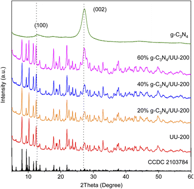
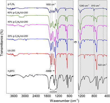
The crystalline structure of the UU-200 and g-C3N4 precursors and the g-C3N4/UU-200 composites was analyzed by means of X-ray diffraction (XRD) (Fig. 1). The XRD pattern of UU-200 matched well with those previously reported (CCDC 2103784),37 and that of g-C3N4 exhibited peaks at 2θ of 13.1° and 27.5° corresponding to the (100) and (002) diffraction planes of g-C3N4 (JCPDS 87-1526), respectively.38,39 Meanwhile, the XRD patterns of the g-C3N4/UU-200 samples were similar to that of UU-200 and showed a peak corresponding to the (002) plane of g-C3N4, whose position was slightly right-shifted, suggesting that g-C3N4 was effectively anchored on the UU-200 surface.The interactions between UU-200 and g-C3N4 were further studied using Fourier transform infrared (FT-IR) spectroscopy (Fig. 2). In the spectrum of the UU-200 catalyst, the stretching vibrations of the carboxylate groups were observed at 1360 and 1549 cm−1, and the Bi–O bond vibration produced a band at 522 cm−1.39 Compared with H3BTC, the stretching vibrations of the carboxylate groups were right-shifted due to the interaction between the Bi(III) ions and the carboxylate groups of the BTC3− linker.22 The FT-IR spectrum of pure g-C3N4 exhibited peaks at 810, 1200 − 1700, and 3100 − 3300 cm−1, which can be ascribed to the characteristic breathing modes of the s-triazine units and sp2 C![[double bond, length as m-dash]](https://www.rsc.org/images/entities/char_e001.gif) N,40 the stretching vibrational modes of C
N,40 the stretching vibrational modes of C![[double bond, length as m-dash]](https://www.rsc.org/images/entities/char_e001.gif) N heterocycles,41 and the N–H stretching vibration,42–44 respectively. The spectra of the g-C3N4/UU-200 composites showed the typical absorption bands of UU-200 and g-C3N4, although a shift in the vibration peaks at 810 and 1240 cm−1 was observed compared with pure g-C3N4, which can be attributed to the interactions between g-C3N4 and UU-200.
N heterocycles,41 and the N–H stretching vibration,42–44 respectively. The spectra of the g-C3N4/UU-200 composites showed the typical absorption bands of UU-200 and g-C3N4, although a shift in the vibration peaks at 810 and 1240 cm−1 was observed compared with pure g-C3N4, which can be attributed to the interactions between g-C3N4 and UU-200.
The morphologies of the binary g-C3N4/UU-200 composites and their individual components were investigated using scanning electron microscopy (SEM) and transmission electron microscopy (TEM) techniques (Fig. 3). It was found that the UU-200 catalyst exhibited condensed bundles with a rod-like shape having a rod thickness of around 200 − 400 nm and smooth surfaces (Fig. 3 A and D), which is in agreement with previously reported experimental data for UUU-200.12 A layered structure containing irregular pieces was observed for g-C3N4 (Fig. 3C). Meanwhile, the TEM images of g-C3N4 showed relatively thin and transparent features with layered wrinkles (Fig. 3 F). The surface of the g-C3N4/UU-200 samples was rougher than that of pure UU-200 (Fig. 3B and S1†), indicating that the UU-200 surface was covered by g-C3N4. The binary composite structure could be observed clearly in the TEM images of the g-C3N4/UU-200 samples (Fig. 3E and S2†). According to these observations, the g-C3N4/UU-200 heterostructure could be expected to be suitable for photocatalysis under visible-light irradiation.
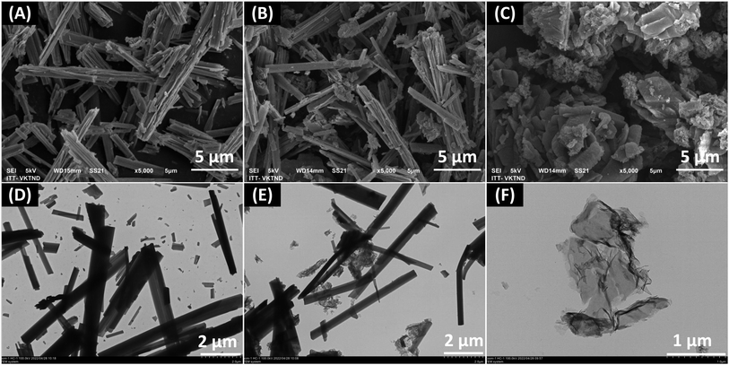 | ||
| Fig. 3 SEM images (A–C) and TEM images (D–F) of UU-200 (A and D), g-C3N4/UU-200 composite (B and E) and g-C3N4 (C and F). | ||
The surface chemical composition and the chemical states of the surface elements present in UU-200, 40% g-C3N4/UU-200, and g-C3N4 were analyzed using X-ray photoelectron spectroscopy (XPS). The XPS survey spectrum of pristine UU-200 showed the presence of Bi, O, and C elements, while that of bare g-C3N4 revealed C, N, and O elements (Fig. S3†). The presence of C, N, O, and Bi elements was detected in the XPS survey spectrum of 40% g-C3N4/UU-200 (Fig. S3†).
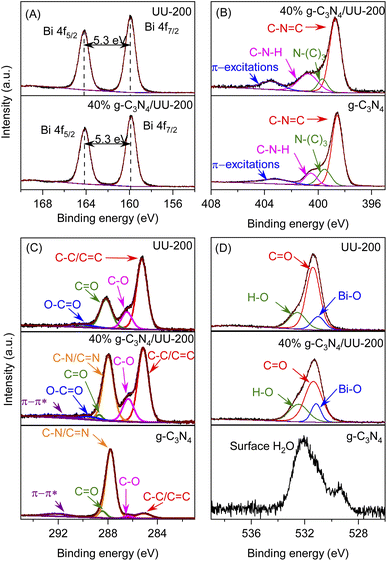
The binding energy (BE) values of the Bi 4f spectra of UU-200 and 40% g-C3N4/UU-200 (Fig. 4A) were located at around 159.5 (Bi 4f7/2) and 164.8 eV (Bi 4f5/2) with a ΔE (Bi 4f5/2–Bi 4f7/2) of 5.3 eV, indicating that Bi was mainly in the form of Bi(III).45 The C 1s peak of 40% g-C3N4/UU-200 can be divided into five main peaks at 284.8, 286.3, 287.9, 288.9, 289.5, and 291.9 eV (Fig. 4C). The peak at 284.8 eV can be attributed to the C–C/C![[double bond, length as m-dash]](https://www.rsc.org/images/entities/char_e001.gif) C bonds of UU-200 and g-C3N4.40,46 The BEs at 286.3 and 288.9 eV correspond to the C–O and C
C bonds of UU-200 and g-C3N4.40,46 The BEs at 286.3 and 288.9 eV correspond to the C–O and C![[double bond, length as m-dash]](https://www.rsc.org/images/entities/char_e001.gif) O bonds, respectively, of UU-200 and g-C3N4.22,47 The peak at 287.9 eV is characteristic of the C–N/C
O bonds, respectively, of UU-200 and g-C3N4.22,47 The peak at 287.9 eV is characteristic of the C–N/C![[double bond, length as m-dash]](https://www.rsc.org/images/entities/char_e001.gif) N bonds of g-C3N4.48 The peak at 289.5 eV can be assigned to the O–C
N bonds of g-C3N4.48 The peak at 289.5 eV can be assigned to the O–C![[double bond, length as m-dash]](https://www.rsc.org/images/entities/char_e001.gif) O bonds of UU-200, and that at 291.9 eV is ascribable to π–π* satellite bands in g-C3N4.49 Fig. 4D shows the O 1s spectra of UU-200, 40% g-C3N4/UU-200, and g-C3N4. For g-C3N4, the deconvoluted peak at 532.0 eV can be ascribed to the surface-adsorbed H2O in the three samples.50,51 The O 1s spectra of UU-200 and 40% g-C3N4/UU-200 exhibited three peaks at 530.9, 531.4, and 532.5 eV, which correspond to Bi–O bands, the carboxylate groups of the BTC linkers, and surface hydroxyl groups, respectively.52,53 The N 1s peak of the 40% g-C3N4/UU-200 composite can be separated into four peaks at 398.7, 399.7, 400.8, and 403.6 eV (Fig. 4 B). These peaks stem from the C–N
O bonds of UU-200, and that at 291.9 eV is ascribable to π–π* satellite bands in g-C3N4.49 Fig. 4D shows the O 1s spectra of UU-200, 40% g-C3N4/UU-200, and g-C3N4. For g-C3N4, the deconvoluted peak at 532.0 eV can be ascribed to the surface-adsorbed H2O in the three samples.50,51 The O 1s spectra of UU-200 and 40% g-C3N4/UU-200 exhibited three peaks at 530.9, 531.4, and 532.5 eV, which correspond to Bi–O bands, the carboxylate groups of the BTC linkers, and surface hydroxyl groups, respectively.52,53 The N 1s peak of the 40% g-C3N4/UU-200 composite can be separated into four peaks at 398.7, 399.7, 400.8, and 403.6 eV (Fig. 4 B). These peaks stem from the C–N![[double bond, length as m-dash]](https://www.rsc.org/images/entities/char_e001.gif) C bonds of the triazine rings, the tertiary nitrogen N–(C)3 groups, the C–N–H bonds of the free amino groups, and π-excitations, respectively.46 Meanwhile, pristine g-C3N4 gave rise to a C–N
C bonds of the triazine rings, the tertiary nitrogen N–(C)3 groups, the C–N–H bonds of the free amino groups, and π-excitations, respectively.46 Meanwhile, pristine g-C3N4 gave rise to a C–N![[double bond, length as m-dash]](https://www.rsc.org/images/entities/char_e001.gif) C peak at 398.5 eV. Compared with pristine g-C3N4, the BE of the C–N
C peak at 398.5 eV. Compared with pristine g-C3N4, the BE of the C–N![[double bond, length as m-dash]](https://www.rsc.org/images/entities/char_e001.gif) C bonds of the 40% g-C3N4/UU-200 composite shifted to higher binding energy by 0.2 eV, revealing an interaction between the Bi and N atoms in the g-C3N4/UU-200 composite. Therefore, the XPS spectra further demonstrated the formation of the binary g-C3N4/UU-200 composites and the interaction between UU-200 and g-C3N4 components. The BEs at 286.3 and 288.9 eV correspond to the C–O and C
C bonds of the 40% g-C3N4/UU-200 composite shifted to higher binding energy by 0.2 eV, revealing an interaction between the Bi and N atoms in the g-C3N4/UU-200 composite. Therefore, the XPS spectra further demonstrated the formation of the binary g-C3N4/UU-200 composites and the interaction between UU-200 and g-C3N4 components. The BEs at 286.3 and 288.9 eV correspond to the C–O and C![[double bond, length as m-dash]](https://www.rsc.org/images/entities/char_e001.gif) O bonds, respectively, of UU-200 and g-C3N4.22,47 The peak at 287.9 eV is characteristic of the C–N/C
O bonds, respectively, of UU-200 and g-C3N4.22,47 The peak at 287.9 eV is characteristic of the C–N/C![[double bond, length as m-dash]](https://www.rsc.org/images/entities/char_e001.gif) N bonds of g-C3N4.48 The peak at 289.5 eV can be assigned to the O–C
N bonds of g-C3N4.48 The peak at 289.5 eV can be assigned to the O–C![[double bond, length as m-dash]](https://www.rsc.org/images/entities/char_e001.gif) O bonds of UU-200, and that at 291.9 eV is ascribable to π–π* satellite bands in g-C3N4.49 Fig. 4D shows the O 1s spectra of UU-200, 40% g-C3N4/UU-200, and g-C3N4. For g-C3N4, the deconvoluted peak at 532.0 eV can be ascribed to the surface-adsorbed H2O in the three samples.50,51 The O 1s spectra of UU-200 and 40% g-C3N4/UU-200 exhibited three peaks at 530.9, 531.4, and 532.5 eV, which correspond to Bi–O bands, the carboxylate groups of the BTC linkers, and surface hydroxyl groups, respectively.52,53 The N 1s peak of the 40% g-C3N4/UU-200 composite can be separated into four peaks at 398.7, 399.7, 400.8, and 403.6 eV (Fig. 4 B). These peaks stem from the C–N
O bonds of UU-200, and that at 291.9 eV is ascribable to π–π* satellite bands in g-C3N4.49 Fig. 4D shows the O 1s spectra of UU-200, 40% g-C3N4/UU-200, and g-C3N4. For g-C3N4, the deconvoluted peak at 532.0 eV can be ascribed to the surface-adsorbed H2O in the three samples.50,51 The O 1s spectra of UU-200 and 40% g-C3N4/UU-200 exhibited three peaks at 530.9, 531.4, and 532.5 eV, which correspond to Bi–O bands, the carboxylate groups of the BTC linkers, and surface hydroxyl groups, respectively.52,53 The N 1s peak of the 40% g-C3N4/UU-200 composite can be separated into four peaks at 398.7, 399.7, 400.8, and 403.6 eV (Fig. 4 B). These peaks stem from the C–N![[double bond, length as m-dash]](https://www.rsc.org/images/entities/char_e001.gif) C bonds of the triazine rings, the tertiary nitrogen N–(C)3 groups, the C–N–H bonds of the free amino groups, and π-excitations, respectively.54 Meanwhile, pristine g-C3N4 gave rise to a C–N
C bonds of the triazine rings, the tertiary nitrogen N–(C)3 groups, the C–N–H bonds of the free amino groups, and π-excitations, respectively.54 Meanwhile, pristine g-C3N4 gave rise to a C–N![[double bond, length as m-dash]](https://www.rsc.org/images/entities/char_e001.gif) C peak at 398.5 eV. Compared with pristine g-C3N4, the BE of the C–N
C peak at 398.5 eV. Compared with pristine g-C3N4, the BE of the C–N![[double bond, length as m-dash]](https://www.rsc.org/images/entities/char_e001.gif) C bonds of the 40% g-C3N4/UU-200 composite shifted to higher binding energy by 0.2 eV, revealing an interaction between the Bi and N atoms in the g-C3N4/UU-200 composite. Therefore, the XPS spectra further demonstrated the formation of the binary g-C3N4/UU-200 composites and the interaction between UU-200 and g-C3N4 components.
C bonds of the 40% g-C3N4/UU-200 composite shifted to higher binding energy by 0.2 eV, revealing an interaction between the Bi and N atoms in the g-C3N4/UU-200 composite. Therefore, the XPS spectra further demonstrated the formation of the binary g-C3N4/UU-200 composites and the interaction between UU-200 and g-C3N4 components.
The physicochemical properties of the samples were investigated via N2 adsorption–desorption isotherms. Fig. 5 displays the N2 adsorption–desorption isotherms and the pore size distribution curves of UU-200, g-C3N4, and the g-C3N4/UU-200 composites. As shown in Fig. 5, all samples exhibited type IV sorption isotherms according to IUPAC classification, indicating their mesoporous characteristics.55 The Brunauer–Emmett–Teller (BET) specific surface area (SBET) values of the 20% g-C3N4/UU-200, 40% g-C3N4/UU-200, and 60% g-C3N4/UU-200 composites were 44.6, 42.8 and 40.1 m2 g−1, respectively, which were higher than that of UU-200 (37.6 m2 g−1) (Table 1). As shown in the SEM results, the presence of g-C3N4 during the synthesis of UU-200 may affect the formation of the condensed bundles of the rod-like crystals of UU-200, resulting in a decrease in their size. The SBET of the composites decreased with the increase of the g-C3N4 loading. Although the SBET values of the g-C3N4/UU-200 composites were lower than that of g-C3N4, they were much higher than that of pristine UU-200, demonstrating that the g-C3N4/UU-200 composites could provide abundant surface active sites and accelerate the transfer of photogenerated charges.56 In addition, the large pore size of 40% g-C3N4/UU-200 can be expected to enhance the adsorption capacity for organic molecules on the surface active sites of the composite, thereby accelerating the photocatalytic activity.
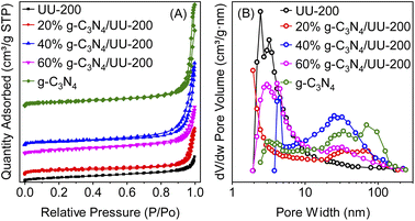 | ||
| Fig. 5 (A) N2 adsorption–desorption isotherms and (B) pore size distributions of g-C3N4. UU-200 and 40% g-C3N4/UU-200 composites. | ||
| Samples | SBET | V | D | Eg | RhB | TCH | ||
|---|---|---|---|---|---|---|---|---|
| (m2 g−1) | (10−3 cm3 g−1) | (nm) | (eV) | k (10−3 min−1) | R2 | k (10−3 min−1) | R2 | |
| UU-200 | 37.6 | 95.9 | 2.45 | 3.77 | 17.4 | 0.987 | 4.33 | 0.983 |
| 20% g-C3N4/UU-200 | 44.6 | 164 | 1.92 | 2.68 | 31.3 | 0.993 | 5.00 | 0.958 |
| 40% g-C3N4/UU-200 | 42.8 | 311 | 4.53 | 2.66 | 38.2 | 0.993 | 5.87 | 0.973 |
| 60% g-C3N4/UU-200 | 40.1 | 178 | 4.15 | 2.64 | 23.6 | 0.983 | 5.63 | 0.974 |
| gC3N4 | 47.1 | 399 | 3.24 | 2.54 | 16.1 | 0.993 | 5.11 | 0.998 |
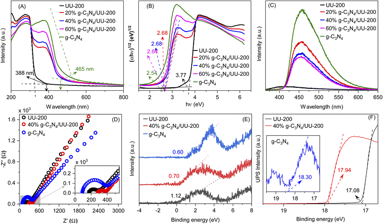
The optical adsorption properties of the g-C3N4/UU-200 composites and their individual components were studied by UV–vis diffuse reflectance spectroscopy (UV–vis DRS) (Fig. 6 A). The photoabsorption edges of UU-200 and g-C3N4 were observed at 330 and 465 nm, respectively. Meanwhile, the UV-vis DRS spectra of the g-C3N4/UU-200 photocatalysts displayed a red shift compared with that of UU-200 because of the distribution of g-C3N4 layers on the UU-200 surface, which suggests that g-C3N4 can extend the absorption of UU-200 into the visible-light region. The energy gaps (Eg) of UU-200, g-C3N4, 20% g-C3N4/UU-200, 40% g-C3N4/UU-200, and 60% g-C3N4/UU-200 were obtained from the plots of (αhν)1/2 versus photon energy (Fig. 6 B), and the estimated values are shown in Table 1.57,58
The recombination of photogenerated charges can create photons, which can be detected with high sensitivity by photoluminescence (PL) emission spectroscopy. Specifically, a lower PL intensity indicates less recombination of photoexcited charge carriers, which is related to higher photocatalytic activity.59 The PL spectra of UU-200, g-C3N4, and 40% g-C3N4/UU-200 composites are presented in Fig. 6C. The highest PL emission peak intensity was observed for g-C3N4 at around 459 nm, indicating its highest recombination of photoexcited charge carriers. However, after the incorporation of UU-200 to construct the g-C3N4/UU-200 composites, the intensity of the PL emission peak decreased, which means that the recombination of charge carriers was comparatively suppressed in the composites. The PL emission analyses revealed that the combination of UU-200 and g-C3N4 efficiently enhanced the separation of charge carriers, thereby improving the photocatalytic activity. Especially, UU-200 exhibited the lowest intensity in the emission peak at around 400 nm, implying the lowest recombination rate of charge carriers. However, the photocatalytic activity of UU-200 was much lower than that of the 40% g-C3N4/UU-200 composite. The highest photocatalytic efficiency of the 40% g-C3N4/UU-200 composite could be ascribed to its low recombination rate of charge carriers. In fact, the strong migration and separation of photoexcited charge carriers was confirmed by analyzing the electrochemical impedance spectra (EIS). Two common methods have applied for treating the impedance data, the Nyquist and the Bode plots.60 Fig. 6D shows the Nyquist impedance plots of the UU-200, g-C3N4, and 40% g-C3N4/UU-200 samples. The corresponding Bodes' plots used to determine the equivalent electrochemical circuit are shown in Fig. S4 (ESI)†. The arc radius on the EIS Nyquist plot shows a clear trend of charge transfer behavior in the three different photocatalysts, which correlates with interfacial charge transport resistance; generally, a small arc radius is indicative of a fast charge transfer rate on the catalyst surface.60,61 As expected, the EIS Nyquist plot of the 40% g-C3N4/UU-200 composite showed a smaller arc radius than that of UU-200, which means that the separation and migration of charge carriers was enhanced in the 40% g-C3N4/UU-200 composite.
To reveal band position of g-C3N4/UU-200, UPS and VB-XPS were investigated. Fig. 6E and F show the XPS-VB spectra and UP spectra of UU-200, g-C3N4, and 40% g-C3N4/UU-200, respectively. The energy difference between the Fermi level and valence band maximum (EF − EVBM) of +0.60, +1.12, and +0.70 eV for UU-200, g-C3N4, and 40% g-C3N4/UU-200, respectively. The work function (φ) of UU-200 (−4.14 eV vs. vacuurn), g-C3N4 (−2.92 eV vs. vacuurn), and 40% g-C3N4/UU-200 (−3.28 eV vs. vacuurn) was calculated from eqn (1). ΔE is the cut-off energy of secondary electron emission spectra (Fig. 6F). Using the above bandgap energies and the eqn (2),62,63 the conduction band (CB) potential of UU-200, g-C3N4, and 40% g-C3N4/UU-200 were estimated, showing that the CB level of UU-200 was more negative than that of g-C3N4. The bandgap structures and charge migration of 40% g-C3N4/UU-200 are described in Fig. S5.†
| φ = 21.22 − ΔE | (1) |
| EVB = Eg + ECB | (2) |
3.2 Photocatalytic performances
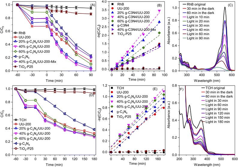
Next, the photocatalytic performance of the g-C3N4/UU-200 composites and their individual components in the degradation of RhB and TCH under visible-light illumination was investigated (Fig. 7A and D). The RhB and TCH degradation hardly occurred in the absence of photocatalysts. In darkness, all the photocatalysts could adsorb certain amounts of RhB (32.5% for UU-200, 26.8% for 20% g-C3N4/UU-200, 20.9% for 40% g-C3N4/UU-200, 11.0% for 60% g-C3N4/UU-200, and 1.59% for g-C3N4) and TCH (28.5% for UU-200, 27.5% for 20% g-C3N4/UU-200, 24.9% for 40% g-C3N4/UU-200, 17.6% for 60% g-C3N4/UU-200, and 4.23% for g-C3N4) and reached the adsorption–desorption equilibrium within 30 min. In the presence of the photocatalysts, the photocatalytic reaction proceeded efficiently under illumination of white LED light. The photocatalytic degradation efficiency for RhB and TCH over UU-200 was 85.0% and 67.6%, respectively. Meanwhile, the addition of g-C3N4 to UU-200 improved the photocatalytic degradation efficiency. Thus, 40% g-C3N4/UU-200 exhibited the highest degradation efficiencies for RhB (97.5%) and TCH (72.6%). The Hinshelwood plot used to study the kinetic of the RhB and TCH photodegradation process and the slopes of the plot show the rate constant for the photodegradation.64,65 The reaction rate constant for the degradation of RhB followed the order of g-C3N4 (0.0161 min−1) < UU-200 (0.0174 min−1) < 60% g-C3N4/UU-200 (0.0236 min−1) < 20% g-C3N4/UU-200 (0.0313 min−1) < 40% g-C3N4/UU-200 (0.0382 min−1) (Fig. 7B). The 40% g-C3N4/UU-200 composite also showed the highest photocatalytic reaction rate constant for the degradation of TCH (0.00587 min−1), which was 1.36, 1.17, 1.04, and 1.15 times higher than that of UU–200 (0.00433 min−1), 20% g-C3N4/UU-200 (0.00500 min−1), 60% g-C3N4/UU-200 (0.00563 min−1), and g-C3N4 (0.00511 min−1), respectively (Fig. 7E). In addition, Fig. 7C and F reveals a change in the absorption spectra of RhB and TCH using 40% g-C3N4/UU-200, respectively, owing to the photocatalytic removal of RhB and TCH during irradiation. Additionally, the photocatalytic performance of a physical mixture containing 40 wt% of g-C3N4 and UU-200 was lower than that of the 40% g-C3N4/UU-200 composite, confirming that the improved photocatalytic activity of the composite stems from the construction of a suitable heterojunction. We also compared the photocatalytic degradation efficiency of the synthesized photocatalyst with commercial TiO2 Degussa P25 (TiO2–P25) photocatalyst. The experimental results indicated that g-C3N4/UU-200 composites exhibited an advantage of RhB (Fig. 7A) and TCH (Fig. 7D) elimination compared with TiO2–P25 under LED light radiation. So, the g-C3N4/UU-200 composite has been considered a potential catalyst for practical application in polluted water treatment.3.3 Photocatalytic mechanism
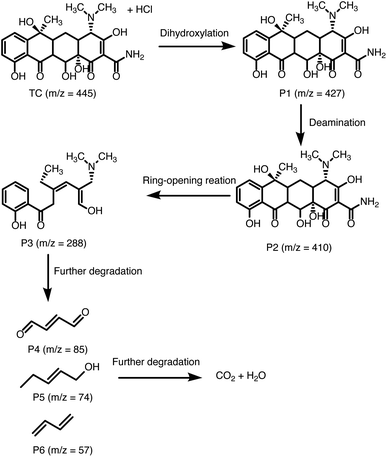
Next, the photocatalytic mechanism of 40% g-C3N4/UU-200 was investigated by determining the main oxidative species involved in the photocatalytic reaction, such as hydroxyl radicals (˙OH), active e−, active h+, and superoxide anion radical (˙O−2) (Fig. 8A, B). In the visible-light photodegradation of RhB, the photocatalytic performance decreased remarkably after adding Na2C2O4 and benzoquinone (BQ), suggesting that both h+ and ˙O−2 are the major reactive species. Meanwhile, the addition of K2Cr2O7 inhibited slightly the photocatalytic process, revealing e− as the secondary active species. In the case of TCH removal over 40% g-C3N4/UU-200, the photocatalytic degradation decreased significantly in the presence of Na2C2O4, K2Cr2O7, and BQ, which indicates that h+, e−, and ˙O−2 play more significant roles in the photocatalytic process than ˙OH.66On the basis of these results, the photocatalytic mechanism depicted in Fig. 8C can be proposed for the photocatalytic degradation of TCH and RhB over 40% g-C3N4/UU-200. Upon exposure to LED light, g-C3N4 in the heterostructure is excited to produce photogenerated e−/h+ pairs. Then, the e− in the CB of g-C3N4 can diffuse to the VB of UU-200 driven by the internal electric field, thus promoting the separation of photogenerated charge carriers. The e− on g-C3N4 can capture surface-absorbed O2 to generate ˙O−2 because the CB level of g-C3N4 is higher than the redox potential of O2/˙O−2 (−0.33 eV vs. NHE),67,68 which is consistent with the results of the trapping test. Meanwhile, the transferred h+ on UU-200 and the remained h+ in the CB of g-C3N4 cannot oxidize the adsorbed H2O to form ˙OH because the EVB of g-C3N4 and UU-200 are lower than the ˙OH/H2O potential (+2.68 eV vs. NHE).69,70 Then, these reactive species (h+, e−, and ˙O−2) can attack the C![[double bond, length as m-dash]](https://www.rsc.org/images/entities/char_e001.gif) C bond of RhB and TCH to generate degradation intermediates. The main byproducts of the visible-light catalytic degradation of TCH by the 40% g-C3N4/UU-200 composite were identified by performing a liquid chromatography–mass spectrometry analysis (Fig. S6†). According to the results, Fig. 9 depicts the possible pathways for the photocatalytic TCH degradation. The characteristic ion signal observed at m/z 445 corresponds to TCH, and its intensity decreased gradually with increasing the irradiation time. Various intermediates were also detected, namely, P1 (m/z 427), P2 (m/z 410), and P3 (m/z 288), which were generated via dihydroxylation, deamination, and ring–opening reactions, respectively.71,72 These intermediates further decomposed into smaller fragments, including P4 (m/z 85), P5 (m/z 74), and P6 (m/z 57). Upon prolonging the irradiation time, all intermediates were converted into H2O and CO2.
C bond of RhB and TCH to generate degradation intermediates. The main byproducts of the visible-light catalytic degradation of TCH by the 40% g-C3N4/UU-200 composite were identified by performing a liquid chromatography–mass spectrometry analysis (Fig. S6†). According to the results, Fig. 9 depicts the possible pathways for the photocatalytic TCH degradation. The characteristic ion signal observed at m/z 445 corresponds to TCH, and its intensity decreased gradually with increasing the irradiation time. Various intermediates were also detected, namely, P1 (m/z 427), P2 (m/z 410), and P3 (m/z 288), which were generated via dihydroxylation, deamination, and ring–opening reactions, respectively.71,72 These intermediates further decomposed into smaller fragments, including P4 (m/z 85), P5 (m/z 74), and P6 (m/z 57). Upon prolonging the irradiation time, all intermediates were converted into H2O and CO2.
3.4 Reusability and stability of the photocatalyst
To examine the photostability of the binary 40% g-C3N4/UU-200 composite, reusability and stability tests were performed. As shown in Fig. S7,† after four cycling tests, the photodegradation efficiency of TCH did not decrease significantly, and 62.8% of TCH was degraded after four cycles of operation, demonstrating the high stability of 40% g-C3N4/UU-200. The slight decrease in the photocatalytic activity of the reused 40% g-C3N4/UU-200 composite can be attributed to the centrifugation process causing a significant loss of photocatalyst during the recovery. Moreover, the stability of the 40% g-C3N4/UU-200 composite upon light irradiation was investigated by performing SEM, XRD, and FT-IR analyses before and after the photoreaction. No noticeable difference was found between the XRD patterns (Fig. S8†) and FT-IR spectra (Fig. S9†) of the 40% g-C3N4/UU-200 catalyst measured before and after four runs, although the intensities of the corresponding peaks decreased significantly, suggesting that the structure and the functional groups remained unaltered. In addition, no obvious change in the SEM images (Fig. S10†) was detected. Taken together, these results demonstrate the good stability and recyclability of the 40% g-C3N4/UU-200 photocatalyst under the experimental conditions.4 Conclusions
In summary, g-C3N4/UU-200 heterojunction photocatalysts were successfully produced via a solvothermal process. RhB and TCH were selected as model organic pollutants to investigate the photodegradation efficiency of the prepared photocatalysts under white LED light irradiation. It was found that the optimal 40% g-C3N4/UU-200 composite exhibited higher photodegradation efficiency for RhB (97.5%) within 90 min and for TCH (72.6%) within 180 min than bare UU-200 and g-C3N4. PL and EIS analyses revealed that the introduction of g-C3N4 on the UU-200 surface resulted in effective charge separation and enhanced photoabsorption efficiency. Therefore, the g-C3N4/UU-200 composite exhibited outstanding photocatalytic behavior in the degradation of RhB and TCH. The photoinduced h+, e−, and . O−2 are the major contributors to the TCH decomposition as confirmed by a trapping test. According to these results, the present study provides new insights into the construction of heterojunction photocatalysts for organic pollutant elimination from water.Author contributions
Trinh Duy Nguyen: writing-original draft, conceptualization, writing – review & editing, supervision. Vinh Huu Nguyen: writing-original draft, methodology, data curation, visualization. Ai Le Hoang Pham: methodology, data curation. Tuyen Van Nguyen: methodology, writing – review & editing. Taeyoon Lee: writing – review & editing, methodology, formal analysis.Conflicts of interest
There are no conflicts to declare.Acknowledgements
This research is funded by Graduate University of Science and Technology under Grant Number GUST.STS.DT2019-HH04.Notes and references
- A. Nezamzadeh-Ejhieh and E. Shahriari, J. Ind. Eng. Chem., 2014, 20, 2719–2726 CrossRef CAS.
- N. Arabpour and A. Nezamzadeh-Ejhieh, Mater. Sci. Semicond. Process., 2015, 31, 684–692 CrossRef CAS.
- H. Derikvandi and A. Nezamzadeh-Ejhieh, J. Hazard. Mater., 2017, 321, 629–638 CrossRef CAS PubMed.
- P. Mohammadyari and A. Nezamzadeh-Ejhieh, RSC Adv., 2015, 5, 75300–75310 RSC.
- S. A. Mirsalari, A. Nezamzadeh-Ejhieh and A. R. Massah, Environ. Sci. Pollut. Res., 2022, 29, 33013–33032 CrossRef CAS.
- Q. Xu, S. Wageh, A. A. Al-Ghamdi and X. Li, J. Mater. Sci. Technol., 2022, 124, 171–173 CrossRef.
- L. Zhang, J. Zhang, H. Yu and J. Yu, Adv. Mater., 2022, 34, 2107668 CrossRef CAS PubMed.
- H. Li, K. Wang, Y. Sun, C. T. Lollar, J. Li and H.-C. Zhou, Mater. Today, 2018, 21, 108–121 CrossRef CAS.
- J. Tang, X. Ma, J. Yang, D.-D. Feng and X.-Q. Wang, Dalton Trans., 2020, 49, 14361–14372 RSC.
- J. Yang, H. Wang, J. Liu, M. Ding, X. Xie, X. Yang, Y. Peng, S. Zhou, R. Ouyang and Y. Miao, RSC Adv., 2021, 11, 3241–3263 RSC.
- A. Bavykina, N. Kolobov, I. S. Khan, J. A. Bau, A. Ramirez and J. Gascon, Chem. Rev., 2020, 120, 8468–8535 CrossRef CAS PubMed.
- S. Zhou, L. Lu, D. Liu, J. Wang, H. Sakiyama, M. Muddassir, A. Nezamzadeh-Ejhieh and J. Liu, CrystEngComm, 2021, 23, 8043–8052 RSC.
- P. Sharafi-Badr, P. Hayati and G. Mahmoudi, Micro and Nano Technologies, Elsevier, 2022, pp. 81–103 Search PubMed.
- Q.-X. Wang and G. Li, Inorg. Chem. Front., 2021, 8, 572–589 RSC.
- G. Wang, Y. Liu, B. Huang, X. Qin, X. Zhang and Y. Dai, Dalton Trans., 2015, 44, 16238–16241 RSC.
- G. Wang, Q. Sun, Y. Liu, B. Huang, Y. Dai, X. Zhang and X. Qin, Chem. - Eur. J., 2015, 21, 2364–2367 CrossRef CAS PubMed.
- M. Savage, S. Yang, M. Suyetin, E. Bichoutskaia, W. Lewis, A. J. Blake, S. A. Barnett and M. Schröder, Chem. - Eur. J., 2014, 20, 8024–8029 CrossRef CAS PubMed.
- M. Feyand, M. Köppen, G. Friedrichs and N. Stock, Chem. - Eur. J., 2013, 19, 12537–12546 CrossRef CAS PubMed.
- A. K. Inge, M. Köppen, J. Su, M. Feyand, H. Xu, X. Zou, M. O'Keeffe and N. Stock, J. Am. Chem. Soc., 2016, 138, 1970–1976 CrossRef CAS PubMed.
- M. Åhlén, E. Kapaca, D. Hedbom, T. Willhammar, M. Strømme and O. Cheung, Microporous Mesoporous Mater., 2022, 329, 111548 CrossRef.
- J. Schneider, M. Matsuoka, M. Takeuchi, J. Zhang, Y. Horiuchi, M. Anpo and D. W. Bahnemann, Chem. Rev., 2014, 114, 9919–9986 CrossRef CAS PubMed.
- V. H. Nguyen, A. L. H. Pham, V.-H. Nguyen, T. Lee and T. D. Nguyen, Chem. Eng. Res. Des., 2022, 177, 321–330 CrossRef CAS.
- D. Jiang, P. Xu, H. Wang, G. Zeng, D. Huang, M. Chen, C. Lai, C. Zhang, J. Wan and W. Xue, Coord. Chem. Rev., 2018, 376, 449–466 CrossRef CAS.
- S.-M. Zhou, D.-K. Ma, P. Cai, W. Chen and S.-M. Huang, Mater. Res. Bull., 2014, 60, 64–71 CrossRef CAS.
- Y. Deng, L. Tang, G. Zeng, Z. Zhu, M. Yan, Y. Zhou, J. Wang, Y. Liu and J. Wang, Appl. Catal., B, 2017, 203, 343–354 CrossRef CAS.
- Y. He, J. Cai, L. Zhang, X. Wang, H. Lin, B. Teng, L. Zhao, W. Weng, H. Wan and M. Fan, Ind. Eng. Chem. Res., 2014, 53, 5905–5915 CrossRef CAS.
- C.-C. Wang, X.-H. Yi and P. Wang, Appl. Catal., B, 2019, 247, 24–48 CrossRef CAS.
- J. Wen, J. Xie, Z. Yang, R. Shen, H. Li, X. Luo, X. Chen and X. Li, ACS Sustainable Chem. Eng., 2017, 5, 2224–2236 CrossRef CAS.
- F. Zhao, Y. Liu, S. B. Hammouda, B. Doshi, N. Guijarro, X. Min, C.-J. Tang, M. Sillanpää, K. Sivula and S. Wang, Appl. Catal., B, 2020, 272, 119033 CrossRef CAS.
- B. Liu, Y. Wu, X. Han, J. Lv, J. Zhang and H. Shi, J. Mater. Sci.: Mater. Electron., 2018, 29, 17591–17601 CrossRef CAS.
- D. Guo, R. Wen, M. Liu, H. Guo, J. Chen and W. Weng, Appl. Organomet. Chem., 2015, 29, 690–697 CrossRef CAS.
- X. Zhang, Y. Yang, W. Huang, Y. Yang, Y. Wang, C. He, N. Liu, M. Wu and L. Tang, Mater. Res. Bull., 2018, 99, 349–358 CrossRef CAS.
- H. Wang, X. Yuan, Y. Wu, G. Zeng, X. Chen, L. Leng and H. Li, Appl. Catal., B, 2015, 174–175, 445–454 CrossRef CAS.
- Z.-D. Lei, Y.-C. Xue, W.-Q. Chen, L. Li, W.-H. Qiu, Y. Zhang and L. Tang, Small, 2018, 14, 1802045 CrossRef.
- X. Li, Y. Pi, L. Wu, Q. Xia, J. Wu, Z. Li and J. Xiao, Appl. Catal., B, 2017, 202, 653–663 CrossRef CAS.
- V. H. Nguyen, L. Van Tan, T. Lee and T. D. Nguyen, Sustainable Chem. Pharm., 2021, 20, 100385 CrossRef CAS.
- M. Åhlén, E. Kapaca, D. Hedbom, T. Willhammar, M. Strømme and O. Cheung, Microporous Mesoporous Mater., 2022, 329, 111548 CrossRef.
- Y. Bai, P.-Q. Wang, J.-Y. Liu and X.-J. Liu, RSC Adv., 2014, 4, 19456–19461 RSC.
- X. Liu, Y. Su, Q. Zhao, C. Du and Z. Liu, Sci. Rep., 2016, 6, 28689 CrossRef CAS PubMed.
- M. Solehudin, U. Sirimahachai, G. A. M. Ali, K. F. Chong and S. Wongnawa, Adv. Powder Technol., 2020, 31, 1891–1902 CrossRef CAS.
- K. Bhunia, M. Chandra, S. Khilari and D. Pradhan, ACS Appl. Mater. Interfaces, 2019, 11, 478–488 CrossRef CAS.
- Y. Zhou, W. Lv, B. Zhu, F. Tong, J. Pan, J. Bai, Q. Zhou and H. Qin, ACS Sustainable Chem. Eng., 2019, 7, 5801–5807 CrossRef CAS.
- S. Ghattavi and A. Nezamzadeh-Ejhieh, Int. J. Hydrogen Energy, 2020, 45, 24636–24656 CrossRef CAS.
- N. Raeisi-Kheirabadi and A. Nezamzadeh-Ejhieh, Int. J. Hydrogen Energy, 2020, 45, 33381–33395 CrossRef CAS.
- M. Guo, Y. Wang, Q. He, W. Wang, W. Wang, Z. Fu and H. Wang, RSC Adv., 2015, 5, 58633–58639 RSC.
- V. H. Nguyen, T. D. Nguyen and T. Van Nguyen, Top. Catal., 2020, 63, 1109–1120 CrossRef CAS.
- P. Wang, Z. Guan, Q. Li and J. Yang, J. Mater. Sci., 2018, 53, 774–786 CrossRef CAS.
- Q. Liang, X. Liu, J. Wang, Y. Liu, Z. Liu, L. Tang, B. Shao, W. Zhang, S. Gong, M. Cheng, Q. He and C. Feng, J. Hazard. Mater., 2021, 401, 123355 CrossRef CAS.
- J. Zou, Y. Yu, W. Yan, J. Meng, S. Zhang and J. Wang, J. Mater. Sci., 2019, 54, 6867–6881 CrossRef CAS.
- C. Liu, X. Dong, Y. Hao, X. Wang, H. Ma and X. Zhang, New J. Chem., 2017, 41, 11872–11880 RSC.
- P. Wang, S. Sun, X. Zhang, X. Ge and W. Lü, RSC Adv., 2016, 6, 33589–33598 RSC.
- D. Xie, Y. Ma, Y. Gu, H. Zhou, H. Zhang, G. Wang, Y. Zhang and H. Zhao, J. Mater. Chem. A, 2017, 5, 23794–23804 RSC.
- R. R. Solís, A. Gómez-Avilés, C. Belver, J. J. Rodriguez and J. Bedia, J. Environ. Chem. Eng., 2021, 9, 106230 CrossRef.
- O. Elbanna, M. Fujitsuka and T. Majima, ACS Appl. Mater. Interfaces, 2017, 9, 34844–34854 CrossRef CAS PubMed.
- K. S. W. Sing, Pure Appl. Chem., 1985, 57, 603–619 CrossRef CAS.
- J. Huang, Q. Tian, H. Feng, C. Xue, J. Li and Q. Xu, Chem. Eng. J., 2022, 447, 137568 CrossRef CAS.
- D. Pradhan and K. T. Leung, Langmuir, 2008, 24, 9707–9716 CrossRef CAS PubMed.
- H. Derikvandi and A. Nezamzadeh-Ejhieh, J. Photochem. Photobiol., A, 2017, 348, 68–78 CrossRef CAS.
- H. Shi, G. Chen, C. Zhang and Z. Zou, ACS Catal., 2014, 4, 3637–3643 CrossRef CAS.
- Z. Amani-Beni and A. Nezamzadeh-Ejhieh, Anal. Chim. Acta, 2018, 1031, 47–59 CrossRef CAS PubMed.
- Y. Liu, F. Le Formal, F. Boudoire and N. Guijarro, ACS Appl. Energy Mater., 2019, 2, 6825–6833 CrossRef CAS.
- S. Samanta, S. Khilari, D. Pradhan and R. Srivastava, ACS Sustainable Chem. Eng., 2017, 5, 2562–2577 CrossRef CAS.
- S. A. Mirsalari and A. Nezamzadeh-Ejhieh, Sep. Purif. Technol., 2020, 250, 117235 CrossRef CAS.
- M. Boudart and G. Djega-Mariadassou, Kinetics of Heterogeneous Catalytic Reactions, Princeton University Press, 2014 Search PubMed.
- M. Mehrali-Afjani, A. Nezamzadeh-Ejhieh and H. Aghaei, Chem. Phys. Lett., 2020, 759, 137873 CrossRef CAS.
- A. Nezamzadeh-Ejhieh and M. Karimi-Shamsabadi, Chem. Eng. J., 2013, 228, 631–641 CrossRef CAS.
- H. Wang, L. Zhang, Z. Chen, J. Hu, S. Li, Z. Wang, J. Liu and X. Wang, Chem. Soc. Rev., 2014, 43, 5234–5244 RSC.
- S. Ghattavi and A. Nezamzadeh-Ejhieh, Composites, Part B, 2020, 183, 107712 CrossRef CAS.
- R. Zhao, X. Sun, Y. Jin, J. Han, L. Wang and F. Liu, J. Mater. Sci., 2019, 54, 5445–5456 CrossRef CAS.
- N. Omrani and A. Nezamzadeh-Ejhieh, Sep. Purif. Technol., 2020, 235, 116228 CrossRef CAS.
- W. Shi, S. Yang, H. Sun, J. Wang, X. Lin, F. Guo and J. Shi, J. Mater. Sci., 2021, 56, 2226–2240 CrossRef CAS.
- W. Wang, K. Xiao, L. Zhu, Y. Yin and Z. Wang, RSC Adv., 2017, 7, 21287–21297 RSC.
Footnote |
| † Electronic supplementary information (ESI) available: Materials, synthesis of UU-200 and g-C3N4, trapping test, recycling test, electrochemical test, SEM and TEM images of g-C3N4/UU200 composites, XPS spectra, LC-mass spectra of TCH, photo-stability of g-C3N4/UU200 composite, and XRD, IR spectra and SEM images of g-C3N4/UU200 composite before and after photocatalytic reaction. See https://doi.org/10.1039/d2ra04222c |
| This journal is © The Royal Society of Chemistry 2022 |

