 Open Access Article
3d Transition metal doping induced charge rearrangement and transfer to enhance overall water-splitting on Ni3S2 (101) facet: a first-principles calculation study†
Minghao Zhang‡
,
Xiaodong Shao‡,
Lu Liu,
Xiaoyong Xu,
Jing Pan * and
Jingguo Hu
 *
*
College of Physics Science and Technology, Yangzhou University, Yangzhou, 225002, China. E-mail: jp@yzu.edu.cn; jghu@yzu.edu.cn
First published on 21st September 2022
Abstract
Cost-efficient bifunctional electrocatalysts with good stability and high activity are in great demand to replace noble-metal-based catalysts for overall water-splitting. Ni3S2 has been considered a suitable electrocatalyst for either the hydrogen evolution reaction (HER) or the oxygen evolution reaction (OER) owing to its good conductivity and stability, but high performance remains a challenge. Based on density functional theory calculations, we propose a practical 3d-transition-metal (TM = Mn, Fe and Co) doping to enhance the catalytic performance for both HER and OER on the Ni3S2 (101) facet. The enhancement originates from TM-doping-induced charge rearrangement and charge transfer, which increases the surface activity and promotes catalytic behavior. In particular, Mn-doped Ni3S2 shows good bifunctional catalytic activity because it possesses more active sites, reduced hydrogen adsorption free energy (ΔGH*) for HER and low overpotential for OER. Importantly, this work not only provides a feasible means to design efficient bifunctional electrocatalysts for overall water-splitting but also provides insights into the mechanism of improving catalytic behavior.
1. Introduction
Hydrogen production using electrochemical water-splitting has been considered one of the most attractive approaches to solving environmental problems and the energy crisis. Two half-reactions are involved in water-splitting: the hydrogen-evolution reaction (HER) and the oxygen-evolution reaction (OER).1,2 Compared to HER, OER is more complex, because there are four sluggish proton-coupled electron-transfer processes. Chemisorption and dissociation of OH− yielding intermediates (HO*, O* and HOO*) are critical to improving the activity of OER.3,4 Pt is the most efficient HER electrocatalyst with near-zero hydrogen adsorption free energy (ΔGH*), while Ir oxides are the most promising electrocatalysts for OER with very small overpotential, but they are far from practical application being subject to scarcity and high cost.5,6 During the water-splitting process, ionized hydrogen ions are equivalent to hydroxide ions. Hydrogen and oxygen generation through overall water-splitting occur at the same time without adding sacrificial agents.7,8 However, most research has focused on improving the catalytic efficiency for the half-reactions, and investigation into efficiently promoting the bifunctional electrocatalysis of both HER and OER has been ignored. Therefore, designing and constructing cost-efficient and bifunctional electrocatalysts with good activity toward overall water-splitting has become one of the most important tasks.Recently, transition-metal dichalcogenides found in abundance in nature, with good surface to volume ratio and low charge carrier diffusion distance have been of wide interest as alternative non-noble-metal-based electrocatalysts, but their catalytic activities are always unsatisfactorily limited by their low electrical conductivity.4,9–11 Ni3S2 naturally emerges as the mineral heazlewoodite and, unlike traditional transition-metal dichalcogenides, it exhibits an intrinsic metallic feature and possesses distinctive conductivity.12 Many reports have shown that Ni3S2-based materials display high electrocatalytic performance for both HER and OER.12–18 For instance, Feng et al. have shown that Ni2S3/NF could display ∼100% faradaic yield for either HER or OER and obtained a current density of 10 mA cm−2 toward HER and OER under small overpotentials of 223 and 260 mV. In particular, Ni3S2 has different fractions of exposed facets, though high-index faced nanosheets possess more active catalytic behaviors but exhibit high surface energies.19 They are usually unstable. The low-index (101) facet is energetically stable, can be easily achieved experimentally, and displays plausible catalytic activity.16,20,21 Doping with impurities is one practical strategy to improve the catalytic activity22,23 Yuan et al. obtained Fe–Ni3S2/FeNi based on the one-step direct growth of metallic iron-nickel sulfide nanosheets on FeNi alloy foils, which exhibited high catalytic activity and long-term stability toward OER with a low overpotential of 282 mV at 10 mA cm−2 and a small Tafel slope of 54 mV dec−1.12 Wang et al. prepared a series of self-supporting M–NiCo2S4/Ni3S2 (M = Mn, Fe, Cu, Zn) nanostructures grown on a nickel foam (NF) skeleton through a one-step hydrothermal strategy. The catalytic performance of Ni3S2-based catalysts could be improved by doping engineering.17 In this work, we find the incorporation of a 3d TM atom (TM = Mn, Fe) can enhance both HER and OER catalytic performance on the Ni3S2 (101) facet. The enhancement comes from TM-doping-induced charge rearrangement and charge transfer, which can be reflected in the following: (1) the systems display more metallic states, showing higher electronic conductivity; (2) the interaction between TM and the active atom becomes stronger, further activating surface activity; (3) the increased electrons concentrate on the active atom, accelerating catalytic behavior. As a result, the Mn-doped Ni3S2 (101) facet exhibits enhanced catalytic activity for overall water-spitting with increased active sites, reduced ΔGH* for HER and overpotential for OER.
2. Computational model and methods
Based on density functional theory (DFT) calculations, generalized gradient approximation with the Perdew–Burke–Ernzerhof (PBE) exchange correlation functional is carried out in the Vienna ab initio simulation package (VASP).24–26 The cutoff energy is 450 eV for the plane wave basis set. The electron–ion interactions are described by the projector-augmented plane wave. The Monkhorst–Pack k-point meshes are 7 × 7 × 1 and 11 × 11 × 1 for geometric optimization and electronic structure, respectively. The convergence thresholds in energy and in force are 1.0 × 10⁻⁵ eV and 0.01 eV Å−1, respectively. The calculated lattice parameters are a = b = 5.754 Å, c = 7.063 Å, in good agreement with the experimental values (a = b = 5.745 Å, c = 7.135 Å).Bulk Ni3S2 is a rhombohedral structure, belonging to the space group R32.27 The Ni3S2 slab is cleaved from the (101) facet of bulk Ni3S2 with a vacuum > 15 Å incorporated to separate the interactions between adjacent images, as shown in Fig. 1. A bilayer 1 × 1 supercell containing 30 atoms is used, displaying a corrugated structure with three Ni atoms and three S atoms exposed to the surface. These six atoms are all considered possible adsorption sites to ensure the most active sites for HER and OER.12,28 To investigate the effect of TM doping on the surface catalytic activity of Ni3S2, one TM atom (Mn, Fe or Co) substitutes an intrinsic Ni atom in the sub-surface, neighbouring a surface active site.
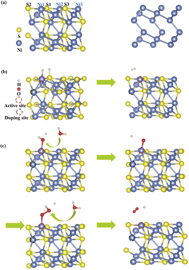 | ||
| Fig. 1 (a) Side views of the Ni3S2 (101) facet and the network of Ni–Ni bonds. Model diagrams of (b) HER and (c) OER on Ni3S2 (101) facets. | ||
HER involves the adsorption of an H atom on the Ni3S2 surface and desorption of H2 from the Ni3S2 surface, as shown in Fig. 1(b), so adsorption free energy of hydrogen (ΔGH*) is a key indicator to evaluate HER activity, which can be defined as ΔGH* = ΔEH* + ΔEZPE − TΔSH*, where ΔEH*, ΔEZPE and ΔSH* are the hydrogen chemisorption energy, zero-point energy change and the entropy of H* adsorption.29,30 The closer ΔGH* approaches zero, the higher the HER activity because atomic hydrogen is in a thermoneutral state, so proton/electron transfer and hydrogen release become more efficient. For the Ni3S2 (101) facet, the ΔGH* are 0.733, 0.735, 0.737, 1.165, 1.249 and 1.287 on Ni1, Ni2, Ni3, S1, S2 and S3, respectively, as shown in Fig. S1 in the ESI.†31 Obviously, Ni atoms are more catalytically favorable than S atoms and Ni1 is the most active site for HER.
For OER, the reaction process is more complex than HER, involving four-electron-transfer steps, as shown in Fig. 1(c), with each step accompanied by proton-removal as follows:
| H2O + * → HO* + H+ + e− |
| HO* → O* + H+ + e− |
| O* + H2O → HOO* + H+ + e− |
| HOO* → * + O2 + H+ + e− |
To verify the reliability of the GGA method, we compare the lattice constant, band structure, ΔGH* and the free energy diagrams of OER on the Ni3S2 (101) facet with the GGA + U method, as shown in Table S1 and Fig. S2 in ESI.†31 The GGA-calculated lattice parameters are a = b = 5.754 Å, c = 7.063 Å, very similar to the GGA + U values (a = b = 5.781 Å, c = 7.135 Å), and very consistent with the experimental values (a = b = 5.745 Å, c = 7.063 Å). Additionally, the band structures, ΔGH* and the free energy diagrams calculated using the two methods are almost the same. The Hubbard term can correct for the interaction of strongly-correlated electrons in the TM atom, but here we focus on electrocatalytic activity, so the Hubbard term has little influence on the results. Thus, we adopt the GGA method to investigate HER and OER activities on Ni3S2 (101) facets.
3. Results and discussion
3.1 Electronic structure of TM-doped Ni3S2 (101) facet
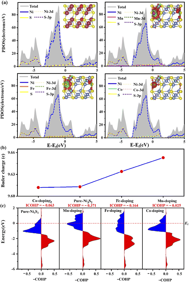
To further investigate the stability of TM-doped Ni3S2, we calculated the formation energy as follows: Ef = ETM@X − EX − (μTM − μNi). The details of the calculation can be found in ref. 36 and 37, and the calculated results show that the formation energies are −0.56, −0.41 and 0.08 eV for Mn, Fe and Co doping, respectively. A more negative value indicates great stability. TM doping induces structural change, as shown in Table S2,† where bond lengths between dopant TM and active-site Ni1 atom are 2.459, 2.452 and 2.441 Å for Mn, Fe and Co doping, in which the Mn–Ni1 bond is close to the original Ni–Ni1 bond length of 2.457 Å. Meanwhile, the bond lengths of Ni–S also change. The structural change will generate an internal field and then induce charge transfer and charge recombination, so the electronic structure changes. Fig. 2(a) shows the electronic structure of (101) faceted Ni3S2, where the system displays metallic behavior as the electronic states come mainly from Ni-3d and S-3p orbitals spread across the Fermi level. This is a distinctive structure in which the Ni–Ni bond connects a continuous network, favoring electron-transfer and thus benefiting the catalytic reaction. For TM (TM = Mn, Fe, Co) doped Ni3S2, the systems continue to exhibit metallic features, and strong hybridization among the Ni-3d, S-3p and TM-3d states occurs near the Fermi level (Ef) [see Fig. 2(a)]. More DOS appears near the Ef especially for Mn-doping, meaning higher conductivity than for pure Ni3S2.12 The change in electronic structure comes from TM-induced charge transfer and charge recombination. The inset in Fig. 2(a) shows the charge density difference of TM-doped Ni3S2, defined as Δρ = ρ(TM-Ni3S2) − ρ(Ni3S2) − ρ(TM), where ρ(TM-Ni3S2), ρ(Ni3S2) and ρ(TM) are the electronic charge densities of TM-doped Ni3S2, isolated Ni3S2 and TM atoms in frozen geometry. There is great electron transfer from dopant TM to neighbouring atoms. Bader charge analysis further verifies that there are 0.43, 0.24 and − 0.05e transfers from dopant Mn, Fe and Co to neighboring atoms and, as a result, there are 9.653, 9.635, 9.611e on the Ni atom for Mn-, Fe-, Co-doped Ni3S2, as shown in Fig. 2(b). The more electrons there are, the better it is to reduce H+ and promote OH− oxidation.To investigate the effect of TM doping on the active site, we further calculate the bond strength of TM-Ni using Crystal Orbital Hamilton Population (COHP) and its integrated values (ICOHP). The positive and negative values in the –COHP curves correspond to the contributions of orbital interaction from bonding and antibonding states.38 As shown in Fig. 2(c), the order of ICOHP is Mn-doping (−0.371) < Fe-doping (−0.164) < pure (−0.063) < Co-doping (−0.025). Based on ICOHP theory, a more negative ICOHP indicates stronger bonding strength. The stronger interaction between TM and the active site has a favorable influence on the catalytic performance.39,40
3.2 Electrochemical overall-water-splitting performance of TM-doped Ni3S2 (101) facet
For HER, ΔGH* is an important indicator. As shown in Fig. 3(a), ΔGH* decreases to 0.565, 0.622 and 0.633 for Mn-, Fe- and Co-doping, respectively, lower than for pure Ni3S2 (ΔGH* = 0.733 eV). TM doping improves HER catalytic activity, especially for Mn-doping. The improvement comes from TM-induced charge rearrangement and charge transfer. The Bader charge analysis in Fig. 3(b) shows that with hydrogen adsorption, there are 9.639, 9.609, 9.603, 9.601e on the active site for Mn-, Fe-, Co-doped and pure Ni3S2. –COHP of the active site Ni and H in Fig. 3(c) shows the ICOHP value order is Mn-doping (−3.543) < Fe-doping (−3.535) < Co-doping (−3.507) < pure Ni3S2 (−3.316). Obviously, the strength of the Ni–H bond in TM-doped Ni3S2 is stronger than that in pure Ni3S2, and Mn-doping is the strongest. Thus, the ΔGH* of TM-doped Ni3S2 decreases, especially with Mn-doping.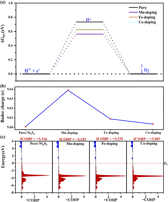 | ||
| Fig. 3 (a) The ΔGH*, (b) the Bader charge on the active-site Ni atom for hydrogen adsorption and (c) the –COHP of Ni–H in pure and TM-doped Ni3S2 (101) facets. | ||
For OER, TM-doping-induced charge redistribution affects the interaction between adsorbate and Ni3S2, which plays an important role in OER efficiency. Fig. 4 shows the free energy diagram of OER on the TM-doped Ni3S2 (101) facet. The first step is H2O adsorption on top of the surface Ni atom, losing one proton to form HO*. The energies rise steeply uphill to 0.96, 1.0, 0.96, 0.90 eV for pure, Mn-, Fe- and Co-doped Ni3S2. Secondly, the HO* loses another Had atom, generating O*, and the energies are 2.62, 2.61, 2.60, 2.61 eV for pure, Mn-, Fe- and Co-doped Ni3S2, respectively. Thirdly, another H2O spontaneously adsorbs on top of the Ni3S2 surface, and a proton in this H2O is removed, forming HOO*. The energies are 4.06, 4.07, 4.06, 3.96 eV for pure, Mn-, Fe- and Co-doped Ni3S2. Finally, O–O separates from the surface. The energy is 4.96 eV. All steps run uphill at U = 0 V, displaying an endothermic process. Though the first and the fourth steps become exothermic reactions, the intermediate steps remain uphill for an equilibrium potential of U = 1.23 V,41 until the applied potentials increase to U = 1.66, 1.61, 1.64, 1.71 V and therefore the overpotentials are 0.43 (= 1.66–1.23), 0.38, 0.41 and 0.48 V for pure, Mn-, Fe- and Co-doped Ni3S2. Though theoretically there is not much increase in overpotential, in fact, experimentally, Fe-doped Ni3S2 exhibits great enhancement in catalytic activity with low onset potential and overpotential, and a small Tafel slope.12 For all Ni3S2 systems, the second step is the rate-determining step, indicating that proton release from the HO* adatom is difficult. For this key step, we compare the binding energy of HO* on the surface with Eb = EHO + E* − EHO*, where EHO, E* and EHO* represent the energy of adsorbate HO and the total energies of (101) facets without and with HO*, respectively. The binding energies are 3.05, 2.99, 3.01 and 3.10 eV for pure, Mn-, Fe- and Co-doped Ni3S2, respectively. Clearly, the binding energy of Mn-doped Ni3S2 is the smallest, indicating the interaction between HO* and the surface is weak, benefiting the conversion of HO* intermediate to O* intermediate.
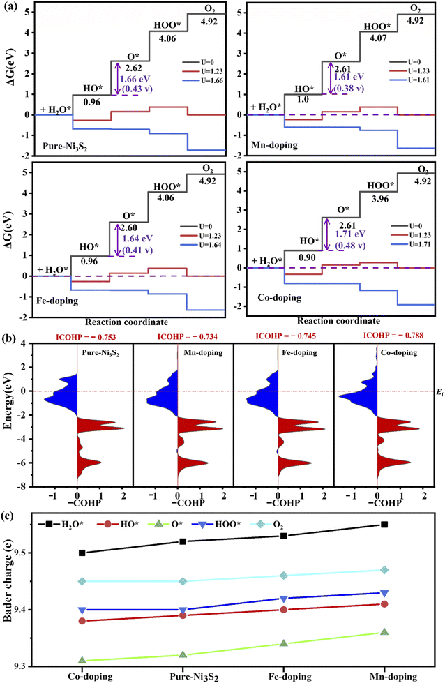 | ||
| Fig. 4 (a) The free energy of four steps at different applied potentials. (b) The –COHP of Ni–O at the second step and (c) the Bader charge on the active-site Ni in pure and TM-doped Ni3S2. | ||
The –COHP curve in Fig. 4(b) shows the bonding strength between the active-site Ni and HO* intermediate. The ICOHP order is Co-doping (−0.788) < pure (−0.753) < Fe-doping (−0.745) < Mn-doping (−0.734). The Ni–O binding strengths of Fe- and Mn-doped Ni3S2 are weaker than those of pure and Co-doped Ni3S2, indicating that the dissociation of O* is easier in Fe- or Mn-doped Ni3S2. The reason can be found from the Bader charge analysis in Fig. 4(c). During the four steps, there are more electrons moving from TM to Ni, especially for Mn-doping. The electrons on the active Ni range from 9.37e to 9.57e. So there are more electrons on the Ni atom at each step for Mn-doped Ni3S2, and the electrons display the ordering: Mn-doping > Fe-doping > pure Ni3S2 > Co-doping. The more electrons accumulate, the higher surface activity. Thus, Mn-doped Ni3S2 possesses higher catalytic activities for both HER and OER.
Fig. 5 shows the high linear correlation between overpotential and ICOHP values. A small ICOHP indicates strong interaction between the active-site Ni and HO* intermediate, corresponding to a small overpotential. Additionally, overpotential and Bader charge also show high linear correlation, but the more electrons there are, the smaller overpotential it is.
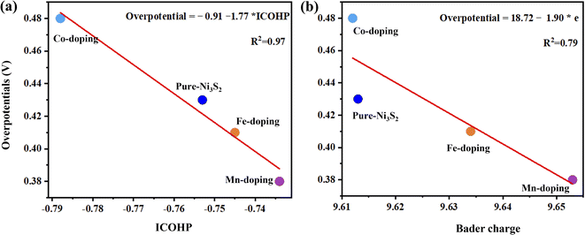 | ||
| Fig. 5 The overpotential as a function of (a) ICOHP values of the active site Ni and HO* intermediate and (b) bader charge of the active site for Ni3S2, and TM-doped Ni3S2 (TM = Mn, Fe, Co). | ||
Here, we focus on the effect of dopant TM on the catalytic activity of Ni3S2 and take acid media as an example. The effect of solution pH values on catalytic activity will be discussed in detail in our subsequent work. In comparison with acid media, we briefly consider alkaline HER and OER, see the ESI.†31 Though HER and OER processes in alkaline media are different from those in acid media, the effect of dopant TM on catalytic activity is the same. During alkaline HER, the second step of H2O dissociation is the rate-determining step for all Ni3S2 systems, Mn-doping decreases the H2O dissociation barrier energy to 1.33 eV, lower than that of pure Ni3S2 at 1.36 eV, as shown in Fig. S3.† During alkaline OER, the second step of forming O* is the rate-determining step with overpotentials of 0.43 (= 0.83–0.4), 0.38, 0.41 and 0.48 V for pure, Mn-, Fe- and Co-doped Ni3S2, as shown in Fig. S4.† As a result, Mn-doped Ni3S2 possesses higher catalytic activities in both acid and alkaline media.
Additionally, we considered the Ni3 atom as the active site for OER activity because Ni3 is also neighboring to doped TM. As shown in Fig. 6, the overpotential is 0.47 V, and a notable reduction can be observed in Mn-doped Ni3S2 with an overpotential of 0.41 V, indicating Mn-doping effectively increases the number of active sites and further enhances OER activity. To investigate the effect of surface size on catalytic activity, we enlarge the supercell to twice as large as previously. The dopant concentration decreases from 5.5% to 2.7%, as shown in Fig. S3 in the ESI,†31 the active site remains the Ni1 atom, and the second step remains the rate-determining step. The free energy at each electric step and the overpotential change little at 0.44 and 0.36 V for 2 × 1 supercells of pure and Mn-doped Ni3S2, very similar to those of 1 × 1 supercells with 0.43 and 0.38 eV for pure and Mn-doped Ni3S2. Thus, the size of the supercell has little influence on the catalytic activity of the active sites. To compare the effect of different dopant positions on the active site, we consider four different dopant positions, as shown in Fig. S6,† and consider the TM atom as acting as the active site. When Mn is doped near active-site Ni1 (see Fig. S6(a) and (b)†), the overpotentials are clearly almost equal at 0.43 and 0.44 V because the distances between dopant Mn and active-site Ni1 are almost equal at 2.457 Å and 2.458 Å. When Mn is doped on the surface and acts as the active site (see Fig. S6(c)†), the overpotential increases greatly to 1.03 V, indicating that the catalytic activity of Ni is stronger than that of Mn and the Mn atom is unsuitable as the active site. Lastly, we doped Mn on the surface to investigate its effect on the active-site Ni1 (see Fig. S6(d)†). The overpotential is 0.81 V, larger than for Mn doped in the sub-surface because there is a competitive effect between Ni1 and Mn, so the adsorbate is adsorbed between them. This indicates that the dopant-TM position has a great influence on the catalytic activity.
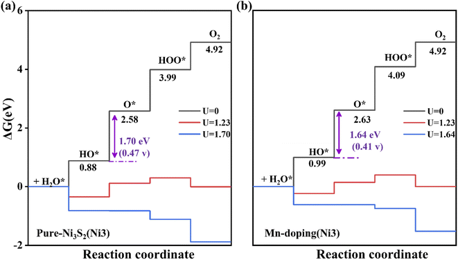 | ||
| Fig. 6 The free energy of four steps for OER on (a) pure and (b) Mn-doped Ni3S2 (101) facets. The Ni3 atom acts as the active site. | ||
4. Conclusion
In summary, based on DFT calculations, we dope an Ni3S2 (101) facet with 3d-TM (TM = Mn, Fe and Co) to improve its bifunctional catalytic activity for either HER or OER. The improvement comes from TM-doping-induced charge rearrangement and charge transfer, which strengthens the interaction between doped TM and the active site because there are more electrons on the active site. In particular, Mn-doping greatly improves the catalytic performance of Ni3S2: (1) the metallic properties indicate good conductivity; (2) the lower ΔGH* indicates enhanced HER activity; (3) the reduced overpotential indicates improvement in OER activity; (4) the increased active sites indicate more conducting paths for HER and OER.Conflicts of interest
There are no conflicts to declare.Acknowledgements
This work is supported by the NSFC (12074332 and 21903014). The authors are grateful for access to the computational resources at YZU.References
- Y. K. Lu, Z. X. Li, Y. L. Xu, L. Q. Tang, S. J. Xu, D. Li, J. J. Zhu and D. L. Jiang, Chem. Eng. J., 2021, 411, 1385–8947 Search PubMed.
- Z. Wang, C. Li and K. Domen, Chem. Soc. Rev., 2019, 48, 2109–2125 RSC.
- Y. Jiao, Y. Zheng, M. Jaroniec and S. Z. Qiao, Chem. Soc. Rev., 2015, 44, 2060–2086 RSC.
- R. Gao and D. Yan, Adv. Energy Mater., 2020, 10, 1–19 Search PubMed.
- Y. Liu, X. Li, Q. Zhang, W. Li, Y. Xie, H. Liu, L. Shang, Z. Liu, Z. Chen, L. Gu, Z. Tang, T. Zhang and S. Lu, Angew. Chem., Int. Ed., 2020, 59, 1718–1726 CrossRef CAS.
- D. V. Esposito, S. T. Hunt, A. L. Stottlemyer, K. D. Dobson, B. E. McCandless, R. W. Birkmire and J. G. Chen, Angew. Chem., 2010, 122, 10055–10058 CrossRef.
- Z. Xu, Y. Ying, G. Zhang, K. Li, Y. Liu, N. Fu, X. Guo, F. Yu and H. Huang, J. Mater. Chem. A, 2020, 8, 26130–26138 RSC.
- E. Hu, Y. Feng, J. Nai, D. Zhao, Y. Hu and X. W. Lou, Energy Environ. Sci., 2018, 11, 872–880 RSC.
- J. Zhang, T. Wang, D. Pohl, B. Rellinghaus, R. Dong, S. Liu, X. Zhuang and X. Feng, Angew. Chem., 2016, 128, 6814–6819 CrossRef.
- J. Wang, W. Fang, Y. Hu, Y. Zhang, J. Dang, Y. Wu, B. Chen, H. Zhao and Z. Li, Appl. Catal., B, 2021, 298, 120490 CrossRef CAS.
- Y. Yang, H. Yao, Z. Yu, S. M. Islam, H. He, M. Yuan, Y. Yue, K. Xu, W. Hao, G. Sun, H. Li, S. Ma, P. Zapol and M. G. Kanatzidis, J. Am. Chem. Soc., 2019, 141, 10417–10430 CrossRef CAS PubMed.
- C. Z. Yuan, Z. T. Sun, Y. F. Jiang, Z. K. Yang, N. Jiang, Z. W. Zhao, U. Y. Qazi, W. H. Zhang and A. W. Xu, Small, 2017, 13, 1–8 Search PubMed.
- X. Li, X. Shang, Y. Rao, B. Dong, G. Q. Han, W. H. Hu, Y. R. Liu, K. L. Yan, J. Q. Chi, Y. M. Chai and C. G. Liu, Appl. Surf. Sci., 2017, 396, 1034–1043 CrossRef CAS.
- J. T. Ren, L. Chen, G. G. Yuan, C. C. Weng and Z. Y. Yuan, Electrochim. Acta, 2019, 295, 148–156 CrossRef CAS.
- X. Feng, Y. Shi, J. Shi, L. Hao and Z. Hu, Int. J. Hydrogen Energy, 2021, 46, 5169–5180 CrossRef CAS.
- Q. Liu, L. Xie, Z. Liu, G. Du, A. M. Asiri and X. Sun, Chem. Commun., 2017, 53, 12446–12449 RSC.
- Y. Wang, N. Chen, X. Du, X. Han and X. Zhang, J. Alloys Compd., 2022, 893, 162269 CrossRef CAS.
- G. Li, X. Cui, B. Song, H. Ouyang, K. Wang, Y. Sun and Y. Wang, Chem. Eng. J., 2020, 388, 124319 CrossRef CAS.
- L. L. Feng, G. Yu, Y. Wu, G. D. Li, H. Li, Y. Sun, T. Asefa, W. Chen and X. Zou, J. Am. Chem. Soc., 2015, 137, 14023–14026 CrossRef CAS PubMed.
- L. Li, C. Sun, B. Shang, Q. Li, J. Lei, N. Li and F. Pan, J. Mater. Chem. A, 2019, 7, 18003–18011 RSC.
- Z. Yu, H. Yao, Y. Yang, M. Yuan, C. Li, H. He, T. S. Chan, D. Yan, S. Ma, P. Zapol and M. G. Kanatzidis, Chem. Mater., 2022, 34, 798–808 CrossRef CAS.
- Z. Xing, D. Wang, T. Meng and X. Yang, ACS Appl. Mater. Interfaces, 2020, 12, 39163–39169 CrossRef CAS PubMed.
- A. C. Thenuwara, N. H. Attanayake, J. Yu, J. P. Perdew, E. J. Elzinga, Q. Yan and D. R. Strongin, J. Phys. Chem. B, 2018, 122, 847–854 CrossRef PubMed.
- J. P. Perdew, A. Ruzsinszky, J. Tao, V. N. Staroverov, G. E. Scuseria and G. I. Csonka, J. Chem. Phys., 2005, 123, 9 CrossRef PubMed.
- G. Kresse and J. Hafner, Phys. Rev. B, 1994, 49, 14251–14269 CrossRef CAS.
- P. E. Blöchl, Phys. Rev. B, 1994, 50, 17953–17979 CrossRef PubMed.
- Y. Aray, D. Vega, J. Rodriguez, A. B. Vidal, M. E. Grillo and S. Coll, J. Phys. Chem. B, 2009, 113, 3058–3070 CrossRef CAS PubMed.
- J. Dong, F. Q. Zhang, Y. Yang, Y. B. Zhang, H. He, X. Huang, X. Fan and X. M. Zhang, Appl. Catal., B, 2019, 243, 693–702 CrossRef CAS.
- T. Liu, P. Diao, Z. Lin and H. Wang, Nano Energy, 2020, 74, 104787 CrossRef CAS.
- J. K. Nørskov, T. Bligaard, A. Logadottir, J. R. Kitchin, J. G. Chen, S. Pandelov and U. Stimming, J. Electrochem. Soc., 2005, 152, J23 CrossRef.
- ESI†.
- X. Cui, P. Ren, C. Ma, J. Zhao, R. Chen, S. Chen, N. P. Rajan, H. Li, L. Yu, Z. Tian and D. Deng, Adv. Mater., 2020, 32, 1–7 Search PubMed.
- Y. Sun, Z. Xue, Q. Liu, Y. Jia, Y. Li, K. Liu, Y. Lin, M. Liu, G. Li and C. Y. Su, Nat. Commun., 2021, 12, 1–8 CrossRef PubMed.
- C. Liu, H. Dong, Y. Ji, T. Hou and Y. Li, Sci. Rep., 2018, 8, 1–9 Search PubMed.
- M. Wang, L. Zhang, J. Pan, M. Huang and H. Zhu, Nano Res., 2021, 14, 4740–4747 CrossRef CAS.
- Q. Wang, Y. Lin, P. Li, M. Ma, V. Maheskumar, Z. Jiang and R. Zhang, Int. J. Hydrogen Energy, 2021, 46, 247–261 CrossRef CAS.
- R. Zhao, L. Zhang, G. Fan, Y. Chen, G. Huang, H. Zhang, J. Zhu and X. Guan, Cem. Concr. Res., 2021, 144, 106420 CrossRef CAS.
- M. Ren, X. Guo and S. Huang, Appl. Surf. Sci., 2021, 556, 149801 CrossRef CAS.
- H. Niu, X. Wang, C. Shao, Z. Zhang and Y. Guo, ACS Sustainable Chem. Eng., 2020, 8, 13749–13758 CrossRef CAS.
- T. Zhang, J. Wu, J. Chen, Q. Pan, X. Wang, H. Zhong, R. Tao, J. Yan, Y. Hu, X. Ye, C. Chen and J. Chen, ACS Appl. Mater. Interfaces, 2021, 13, 24682–24691 CrossRef CAS PubMed.
- H. Dau, C. Limberg, T. Reier, M. Risch, S. Roggan and P. Strasser, ChemCatChem, 2010, 2, 724–761 CrossRef CAS.
Footnotes |
| † Electronic supplementary information (ESI) available. See https://doi.org/10.1039/d2ra04252e |
| ‡ These authors contributed equally. |
| This journal is © The Royal Society of Chemistry 2022 |

