 Open Access Article
Polyimide-derived porous carbon/Co particle-based composites for high-performance microwave absorption†
Wentao Yu ,
Yonggang Min
 *,
Jiyong Fang
 *,
Xiaochuang Lu,
Ziqing Wang and
Lingfeng Jian
School of Materials and Energy, Guangdong University of Technology, Guangzhou 510006, China. E-mail: ygmin@gdut.edu.cn
First published on 12th October 2022
Abstract
A simple method that combines liquid–liquid phase separation and high-temperature pyrolysis has been developed for the synthesis of polyimide-derived porous carbon/Co particle-based composite absorbers (PIC/Co-800 and PIC/Co-1000). The excellent heat resistance of polyimide allows the composite precursor to maintain its porous structure during pyrolysis. According to the results, PIC/Co-800 and PIC/Co-1000 have a coral-like porous structure, which can enhance the impedance matching property and microwave attenuation ability of the synthesized materials. The impedance matching condition and dissipation ability of PIC/Co-800 and PIC/Co-1000 have been enhanced due to the synergistic effect between the carbon-induced dielectric loss and Co nanoparticle-induced magnetic loss. PIC/Co-1000 shows the highest absorption performance with a minimum reflection loss (RL) of −40.22 dB at a thickness of 5.3 mm and an effective absorption bandwidth (EABW, RL ≤ −10 dB) of 4.10 GHz at a thickness of 1.4 mm. With thicknesses in the range of 1.4 mm to 5.3 mm, the minimum RL value of each thickness is lower than −15 dB. Therefore, this work provides a new strategy for the synthesis of promising absorbing materials with outstanding EMW absorption performance.
Introduction
With the rapid development of electrical technology and devices, electromagnetic wave (EMW)-induced pollution has caused extensive concern.1,2 Excessive EMWs may damage electrical equipment and threaten human health simultaneously.3,4 Therefore, the exploration of an efficient way to attenuate or shield EMW radiation is an urgent aim. Compared with EMW-shielding materials, EMW-absorbing materials have attracted more attention as they can convert excessive EMWs into thermal energy rather than simply reflecting them. Therefore, the application of EMW-absorbing materials can prevent the secondary pollution of EMWs. Consequently, developing EMW-absorbing materials is now a hotspot in the field of EMW protection.In general, the primary characteristics of an excellent EMW absorber are a strong absorption ability, wide absorption frequency range, light weight, and low thickness, all of which vary based on the requirements of the application.5 Many materials can serve as ideal EMW-absorbing materials, such as metal nanoparticles (Fe, Co, Ni),6–8 ferrite (Fe3O4),9–11 and conductive polymers (polypyridine).12,13 In recent years, carbon materials such as graphene (G) derivatives,14–16 carbon fibre (CF),17,18 and carbon nanotubes (CNTs)19,20 have been widely studied because of their chemical resistance, low density, and high dielectric constants. However, to achieve outstanding EMW absorption performance, strong dielectric loss, strong magnetic loss, and fine electromagnetic impedance matching are indispensable factors. Unilateral carbon materials operate with only dielectric loss; thus, their poor impedance matching does not meet the aforementioned requirements. Instead, the combination of carbon materials and magnetic materials, which can overcome the disadvantages of unilateral carbon materials, might be a solution for obtaining good EMW absorption performance. Gao et al. designed and synthesized a two-dimensional N-doped carbon/FeC3 (ref. 21) composite absorber with melamine and Fe(NO)3·9H2O as precursors. A minimum reflection loss (RL) value of −46.78 dB can be achieved at 13.53 GHz for N-doped carbon/FeC3. Li et al. designed a series of MWCNT and Ni-based composite absorbers (Ni@MWCNTs) via a blending method. The minimum RL can reach as low as −42.30 dB at 11.20 GHz.22 After heat treatment at 700 °C, the RL value of the absorbers was −17.10 dB, and the effective absorption bandwidth (EABW, RL ≤ −10 dB) was 7.10 GHz. However, traditional magnetic materials have a large density, which may increase the composite's density and fail to fit the requirements of being thin and light.23,24
Hollow or porous structures not only have reduced weight but also improve the specific surface area and transmission efficiency compared to those of traditional materials. Moreover, the porous structure can improve the material's impedance matching by incorporating air, which has a low dielectric constant. Many studies on porous or core–shell structures have been reported in this field.25–29 In summary, the construction of porous structures plays a crucial role in improving the EMW absorption performance. So far, the complexity of the design and construction of porous structures has limited their large-scale fabrication. Therefore, there is an urgent need to develop a simple, low-cost and controllable synthetic method for porous carbon/magnetic EMW absorbers.
In this work, we report a simple, effective method for preparing porous carbon/magnetic nanoparticle EMW absorbers via the liquid–liquid phase separation method. We chose polyimide (PI) as the carbon source because of its excellent heat resistance and ease of modification.30–32 In addition, the porous carbonized PIC/Co showed excellent EMW absorption performance. This method is simple, repeatable and suitable for large-scale preparation to create excellent carbon-based EMW absorbers.
Experimental
Synthesis of the polyimide-derived porous carbon/Co particle-based composites (PIC/Co)
Typically, the polyimide-derived porous carbon/Co particle-based composites were synthesized by combining liquid–liquid phase separation and high-temperature pyrolysis, as shown in Scheme 1. First, 10.0 g dimethylacetamide (DMAC) and 3.5 g CoCl2·H2O were added to a 30.0 g polyamic acid (PAA) solution. This mixture was stirred for 1 hour at room temperature. Second, this solution was cast on a glass plate with an aluminium casting knife, and the corresponding solution membrane was immediately immersed in a water bath at 25 °C for 24 hours. Third, the membrane was dried and then pyrolyzed in a tubular furnace under a flowing argon gas atmosphere following an appropriate heating procedure (imidization: 150 °C, 1 hour; 250 °C, 1 hour; 350 °C, 1 hour, carbonization: 350–600 °C, 5 °C min−1; 600–1000 °C, 1 °C min−1; 1000 °C, 1 hour). The product was named PIC/Co-1000. To determine the appropriate calcination temperature, the membrane was also carbonized at 800 °C and named PIC/Co-800. For comparison, samples without the addition of the Co particle precursor (CoCl2·H2O) were also synthesized via a similar method, which were named PIC-800 and PIC-1000. | ||
| Scheme 1 Synthetic route of the polyimide-derived porous carbon/Co particle-based composites (PIC/Co-800 and PIC/Co-1000). | ||
Material characterization
The thermal properties of the samples were determined via thermogravimetric analysis (TGA, PerkinElmer, heating rate: 10 °C min−1; gas flow: 50 mL min−1). The chemical structures of the samples were obtained via X-ray powder diffraction (XRD, D/MAX-Ultima IV, Cu Kα, 10°–80°, 10° min−1), Raman spectroscopy (LabRAM HR Evolution, 523 nm laser), and Fourier transform infrared spectroscopy (FT-IR, Nicolet 6700). The morphology of the synthesized materials was determined via scanning electron microscopy (SEM, Nova Nano 450). The magnetic properties were measured on a vibrating sample magnetometer (VSM, LakeShore 7404, 298 K). The electromagnetic parameters (complex permeability and permittivity) were measured on a network analyzer (N5244A PNA-X, Agilent, toroidal-shaped samples with 25 wt% products in a paraffin wax matrix, coaxial waveguide method, frequency range: 2–18 GHz).Results and discussion
A one-step method to prepare a porous carbon/magnetic nanoparticle EMW absorber via the liquid–liquid phase separation method and pyrolysis process has been designed. As shown in Scheme 1, the porous carbon/magnetic composites were synthesized from porous polymer membranes containing PI as the carbon source and cobalt metal salt (CoCl2) as the magnetic particle source. Then, the prepared polymer membranes were subjected to imidization and carbonization via thermal treatment under appropriate conditions. The imidization of PAA is evident in the FT-IR spectra shown in Fig. 1(a). The presence of the PAA material is confirmed by the characteristic peaks at 1720, 1660, and 1560 cm−1 for the C![[double bond, length as m-dash]](https://www.rsc.org/images/entities/char_e001.gif) O (acid), C
O (acid), C![[double bond, length as m-dash]](https://www.rsc.org/images/entities/char_e001.gif) O (amide), and C–N (amide) stretching vibrations, respectively. PAA was then transformed into PI via thermal imidization, as shown by the characteristic absorption double-peaks at 1781 and 1720 cm−1 for the symmetric and asymmetric C
O (amide), and C–N (amide) stretching vibrations, respectively. PAA was then transformed into PI via thermal imidization, as shown by the characteristic absorption double-peaks at 1781 and 1720 cm−1 for the symmetric and asymmetric C![[double bond, length as m-dash]](https://www.rsc.org/images/entities/char_e001.gif) O stretching vibrations of the imide group, respectively, and the peak shifts at 1376 cm−1 and 725 cm−1 for the C–N–C stretching vibration of PI. To determine the thermal properties of the synthesized PI, the TGA and DTG results are shown in Fig. 1(b). The 5% weight-loss temperature and initial weight-loss temperature were 548 °C and 592 °C, respectively.
O stretching vibrations of the imide group, respectively, and the peak shifts at 1376 cm−1 and 725 cm−1 for the C–N–C stretching vibration of PI. To determine the thermal properties of the synthesized PI, the TGA and DTG results are shown in Fig. 1(b). The 5% weight-loss temperature and initial weight-loss temperature were 548 °C and 592 °C, respectively.
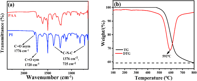 | ||
| Fig. 1 (a) FT-IR spectra of PAA and the corresponding PI and (b) the TGA and DTG curves of the PI used in this work. | ||
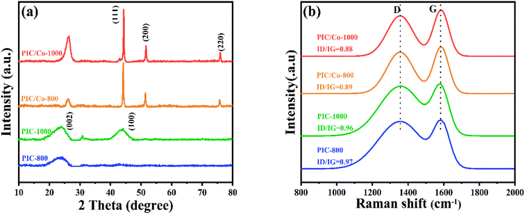
To further confirm the changes to the cobalt metal salt, the XRD patterns were recorded. As shown in Fig. 2(a), after pyrolysis at 1000 °C, PI was carbonized; a broad diffraction peak at 20°–25° was detected due to the low graphitization degree of PIC. Additionally, for PIC/Co, the characteristic peaks at 44.21°, 51.51°, and 75.51° are assigned to the (111), (200), and (220) planes, respectively, of the face-centred cubic structure of Co nanoparticles (fcc-Co).38 Thus, when the PAA/CoCl2 composite underwent the carbonization process, the cobalt salt was chemically reduced to Co particles. Additionally, the graphitization peaks at 20°–25° become narrower than those of PIC, indicating a relatively high degree of graphitization in PIC/Co, which implies that Co particles catalysed the crystallization process of PIC. This result was further verified using Raman spectroscopy, as depicted in Fig. 2(b). The Raman spectra show two board peaks at approximately 1360 cm−1 and 1592 cm−1, which are attributed to the D and G bands, respectively, of carbonaceous materials. The intensity ratios of the D/G bands of PIC-800, PIC/Co-800, PIC-1000, and PIC/Co-1000 are 0.97, 0.89, 0.96, and 0.88, respectively. Therefore, under the catalysis of Co particles, PIC/Co-800 and PIC/Co-1000 have a higher degree of graphitization compared with PIC-800 and PIC-1000, respectively.
The change in morphology from the precursor PAA membrane to PIC and PIC/Co was characterized by scanning electron microscopy. As shown in Fig. 3(a) and (b), during the phase-separation process, the exchange of DMAC and water created obvious wormhole-like pores inside the PAA membrane.
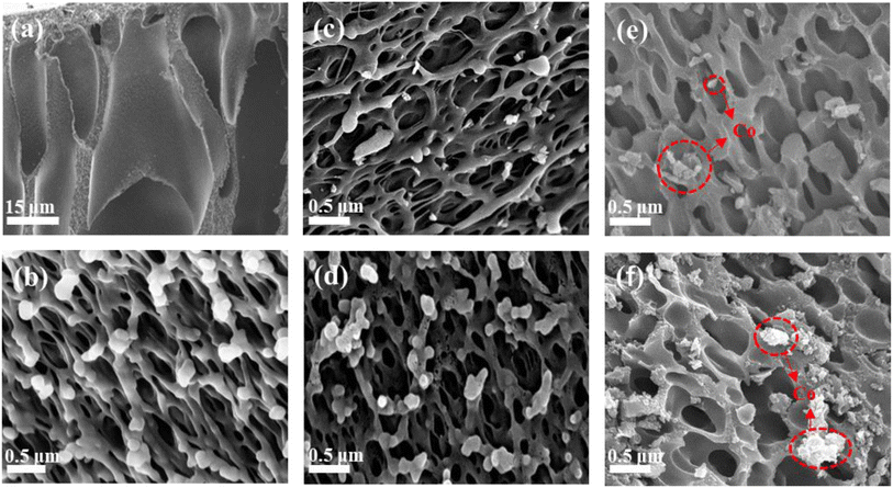 | ||
| Fig. 3 SEM images of (a and b) porous PAA, (c) PIC-800, (d) PIC-1000, (e) PIC/Co-800, and (f) PIC/Co-1000. | ||
Further, there are coral-like pores observed as a substructure on the wormhole-like pore surface. It can be seen that the coral-like pore size is about 400–500 nm. After imidization and carbonization, the pore size and structure of PIC-800 and PIC-1000 did not show any obvious change, as shown in Fig. 3(c) and (d), respectively. This means that carbonization had little impact on the pore morphology because of PI's excellent heat resistance and structural stability. As shown in Fig. 3(e) and (f), Co nanoparticles with a size of about 200 nm were randomly dispersed on the surface of PIC. Therefore, the porous PIC and Co nanoparticle composites were successfully synthesized as expected.
To verify the EMW absorption ability of our PIC/Co-800 and PIC/Co-1000 composites, the complex permittivity and complex permeability are shown in Fig. 4. The real part (ε′) of complex permittivity (εr = ε′ − iε′′) and the real part (μ′) of complex permeability (μr = μ′ − iμ′′) are related to the storage of EMW energy, and their imaginary parts (ε′′ and μ′′, respectively) represent the dissipation of EMW energy. As shown in Fig. 4(a), PIC/Co-1000 has larger ε′ (11.85–6.49) and ε′′ (4.72–2.78) values than PIC/Co-800 (8.78–7.65 and 1.33–1.25, respectively), with a stronger dependence on the EMW frequency. The real and imaginary parts of permittivity are connected to the polarization and dielectric loss, which suggests that PIC/Co-1000 has a relatively strong dielectric loss performance. Fig. 4(b) shows the real and imaginary parts of the complex permeability of the PIC/Co-1000 nanocomposite. PIC/Co-1000 exhibited high μ′ and μ′′ (1.08–0.93 and 0.04–0.008, respectively). In general, these samples have weak magnetic loss relative to their dielectric loss, which can be attributed to the low content of magnetic Co nanoparticles (see the content information of Co particles in PIC/Co-800 and PIC/Co-1000 in Fig. S2 in the ESI†).
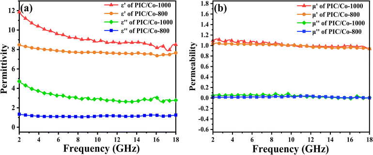 | ||
| Fig. 4 Relative (a) permittivity and (b) permeability of PIC/Co-800 and PIC/Co-1000 with absorber contents of 25%. | ||
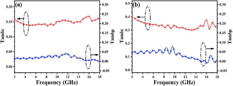
The dielectric tangent loss (tan![[thin space (1/6-em)]](https://www.rsc.org/images/entities/char_2009.gif) δε = ε′′/ε′) and magnetic tangent loss (tan
δε = ε′′/ε′) and magnetic tangent loss (tan![[thin space (1/6-em)]](https://www.rsc.org/images/entities/char_2009.gif) δμ = μ′′/μ′) are common quantities used to determine the dielectric and magnetic loss abilities, respectively, of EMW absorbers. As shown in Fig. 5(a), the variations in tan
δμ = μ′′/μ′) are common quantities used to determine the dielectric and magnetic loss abilities, respectively, of EMW absorbers. As shown in Fig. 5(a), the variations in tan![[thin space (1/6-em)]](https://www.rsc.org/images/entities/char_2009.gif) δε and tan
δε and tan![[thin space (1/6-em)]](https://www.rsc.org/images/entities/char_2009.gif) δμ are associated with ε′′ and μ′′, respectively. Because the absorption properties are associated with tan
δμ are associated with ε′′ and μ′′, respectively. Because the absorption properties are associated with tan![[thin space (1/6-em)]](https://www.rsc.org/images/entities/char_2009.gif) δε and tan
δε and tan![[thin space (1/6-em)]](https://www.rsc.org/images/entities/char_2009.gif) δμ, the high tan
δμ, the high tan![[thin space (1/6-em)]](https://www.rsc.org/images/entities/char_2009.gif) δε values imply that the dielectric loss might make a major contribution to the absorption property in the case of PIC/Co-1000 and PIC/Co-800, while the magnetic Co particles were used as an accessorial promoter to achieve better impedance matching, which can also contribute to the final EMW absorption performance. Moreover, although the difference in tan
δε values imply that the dielectric loss might make a major contribution to the absorption property in the case of PIC/Co-1000 and PIC/Co-800, while the magnetic Co particles were used as an accessorial promoter to achieve better impedance matching, which can also contribute to the final EMW absorption performance. Moreover, although the difference in tan![[thin space (1/6-em)]](https://www.rsc.org/images/entities/char_2009.gif) δμ between PIC/Co-800 and PIC/Co-1000 is small, the tan
δμ between PIC/Co-800 and PIC/Co-1000 is small, the tan![[thin space (1/6-em)]](https://www.rsc.org/images/entities/char_2009.gif) δε of PIC/Co-1000 is higher than that of PIC/Co-800. Therefore, PIC/Co-1000 has a higher EMW loss ability than PIC/Co-800.
δε of PIC/Co-1000 is higher than that of PIC/Co-800. Therefore, PIC/Co-1000 has a higher EMW loss ability than PIC/Co-800.
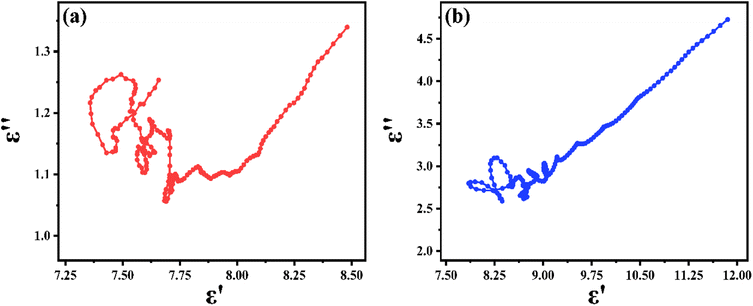
For dielectric loss materials, the dielectric loss can be divided into polarization loss and conduction loss in the measured 2–18 GHz range. To investigate the dielectric mechanisms of PIC/Co-800 and PIC/Co-1000, the plots of ε′′ versus ε′ are shown in Fig. 6(a) and (b), respectively. According to these results, PIC/Co-800 and PIC/Co-1000 have several semicircular segments. Hence, multiple dielectric relaxations occur. Moreover, there is also a linear segment in the plot of ε′′ versus ε′, which represents the conduction-induced dielectric loss.39 Therefore, according to Fig. 4 and 6, the conductive loss is mainly in the range of 2–5 GHz, while the dipolar polarization is mainly in the range of 5–18 GHz.
To investigate the EMW absorption performance of PIC/Co, the reflection loss (RL), which is a function determined theoretically by the obtained electromagnetic parameters, was studied. According to transmission line theory, the RL can be calculated with the measured EMW parameters of the synthesized materials using the following equations:33
RL = 20![[thin space (1/6-em)]](https://www.rsc.org/images/entities/char_2009.gif) lg|(Zin − Z0)/(Zin + Z0)| lg|(Zin − Z0)/(Zin + Z0)|
| (1) |
 | (2) |
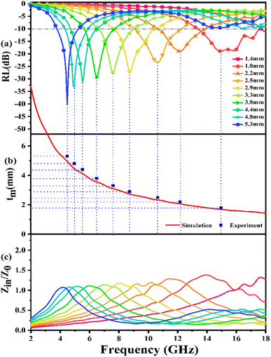
Fig. 7(a) presents the calculated RL curves of PIC/Co-1000. When the content of the absorber is 25 wt%, PIC/Co-1000 shows a strong EMW loss ability (RL < −10 dB) when the thickness is more than 1.4 mm. When the thickness is 5.3 mm, PIC/Co-1000 has the strongest EMW loss ability at 4.56 GHz, and the RL is −40.22 dB (over 99.99% absorption). When the thickness of PIC/Co-1000 is 1.9 mm, the EMW loss of PIC/Co-1000 in the frequency range of 17.5–13.4 GHz is more than −10 dB, showing a broadband absorption characteristic (4.1 GHz). In addition, when the thickness is between 1.4 and 5.3 mm, PIC/Co-1000 shows strong absorption of electromagnetic waves in the frequency range of 3.8–18 GHz, and the maximum reflection loss of each thickness is more than −15 dB. As shown in Fig. S3,† the EMW absorption performance of PIC/Co-800 is not as good when as that of PIC/Co-1000. As mentioned above, PIC/Co-1000 has a stronger EMW loss ability than PIC/Co-800. Therefore, the difference in EMW attenuation ability yields a significant difference in EMW absorption performance.
To further investigate the EMW performance of PIC/Co-1000, a single-layer homogeneous absorber model was used. As shown in Fig. 8, the interaction between the incident EMW energy (E0) and the absorber layer can be divided into three parts: the reflected EMW energy on the air–absorber interface (E1), the absorbed EMW energy inside the absorber (E2), and the reflected EMW energy on the absorber–metal interface (E3).34 An excellent EMW absorber should have a low E1, high E2, and low E3.
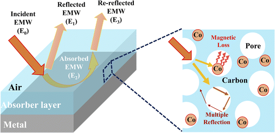 | ||
| Fig. 8 Single-layer homogeneous absorber model for EMW absorption and the enhanced interaction via multiple reflections and scattering between the EMWs and PIC/Co. | ||
The impedance matching characteristic (Z), which is an important parameter for reducing E1, is expressed by the following equation:
 | (3) |
The frequency dependence of Z for PIC/Co-1000 is depicted in Fig. 7(c). At the absorber layer thicknesses of 4.4, 4.8, and 5.3 mm, the corresponding Z values are approximately 1 at 4.48, 4.96, and 5.52 GHz, respectively. Moreover, a minimum RL is obtained at these frequencies. Interestingly, coral-like pore structures can be assumed to be two-phase composites containing solids (carbon) and pores (air). This structural framework can lower the effective permittivity and maintain a balance between permittivity and permeability.36 Therefore, the EMW can easily propagate into the absorber to be attenuated instead of being reflected at the absorber surface (low E1). This is the precondition for EMW absorption.
As discussed above, PIC/Co-1000 has a relatively strong EMW attenuation ability. The incident EMW can be attenuated through dielectric loss and magnetic loss at the same time (high E2). This is the key factor in EMW absorption.
Further, according to the quarter-wavelength cancellation model, it is known that at a proper thickness, the EMWs from the air–absorber interface (E1) and absorber–metal interface (E3) are out of phase by 180°, leading to their extinction at the air–absorber interface. Thus, minimal reflection can be achieved at a certain EMW frequency (fm, frequency related to the minimum RL value) if the thickness (tm) of the absorber composite satisfies the following matching equation:35
 | (4) |
According to this model, the peak frequency is inversely proportional to the thickness. As shown in Fig. 7(b), all the red symbols (thickness related to the minimum RL value in Fig. 7(a)) are located around the λ/4 curve (the blue line; λ is the wavelength of the EMW). Consequently, the PIC/Co-1000-based EMW absorber obeys the 1/4λ matching conditions and thus contributes to the attenuated EMW absorption performance of PIC/Co-1000.
Therefore, the fine impedance matching condition, the relatively strong EMW attenuation ability, and the 1/4λ matching conditions endow PIC/Co-1000 with excellent absorption performance.
As shown in Fig. 8, the incident EMW (E0) can be divided into three parts: reflected EMW (E1), absorbed EMW (E2), and transmitted EMW (E3). Moreover, the reflection of the EMW includes surface reflections and multiple reflections. Moreover, the multiple reflections or scattering inside the synthesized absorber PIC/Co may lead to extended transmission routes of the EMW, which in turn improves the interaction between the EMW and absorber, achieving better EMW absorption performance.37 Further, PIC/Co could effectively reduce the reflection of EMW at the air–absorber interface and enhance the absorption of the incident EMW (E1) in the absorber layer, as demonstrated above. Accordingly, it can be concluded that PIC/Co exhibits good EMW absorption performance. Considering the EMW absorption performance, PIC/Co with a specially designed honeycomb-like porous structure is expected to be used as the first layer of multilayer EMW-absorbing materials to promote incident EMWs.
Conclusions
In summary, polyimide-derived porous carbon/magnetic EMW absorbers (PIC/Co-800 and PIC/Co-1000) were successfully synthesized by combining the liquid–liquid phase separation process with the pyrolysis method. The porous structure remaining intact during pyrolysis due to the excellent heat resistance is a major contributor to the improved EMW absorption. Furthermore, coral-like pore structures improve the impedance matching and interfacial polarization. Importantly, the EM impedance matching condition and the EMW dissipation ability of the absorber are attributed to the synergistic effect of carbon-induced dielectric loss and Co nanoparticle-induced magnetic loss. At the thicknesses of 1.4 mm and 5.3 mm, PIC/Co-1000 achieves minimum RL values of −18.97 and −40.22 dB at 14.96 and 4.48 GHz as well as EABWs of 4.10 and 1.36 GHz, respectively. Moreover, the minimum RL at each thickness is lower than −15 dB in the thickness range of 1.4–5.3 mm. Accordingly, the design strategy presented in this work can be extended to synthesize other high-performance absorbers and mitigate EMW-induced pollution.Conflicts of interest
There are no conflicts to declare.Acknowledgements
The authors gratefully acknowledge Foshan Introducing Innovative and Entrepreneurial Teams (No. 1920001000108). Guangzhou Hongmian Project (No. HMJH-2020-0012). National Key R&D Program of China (No. 2020YFB0408100), Guangdong Innovative and Entrepreneurial Research Team Program (No. 2016ZT06C412), and National Natural Science Foundation of China (NSFC; No. U20A20340).Notes and references
- X. J. Zeng, X. Y. Cheng, R. H. Yu and G. D. Stucky, Carbon, 2020, 168, 606–623 CrossRef CAS.
- W. T. Cao, F. F. Chen, Y. J. Zhu, Y. G. Zhang, Y. Y. Jiang, M. G. Ma and F. Chen, ACS Nano, 2018, 12, 4583–4593 CrossRef CAS PubMed.
- Y. N. Shen, Q. H. Li, S. L. Xu and X. Liu, Cem. Concr. Res., 2021, 143, 106389–106403 CrossRef.
- Q. W. Zeng, L. Wang, X. Li, W. B. You, J. Zhang, X. H. Liu, M. Wang and R. C. Che, Appl. Surf. Sci., 2021, 538, 148051 CrossRef CAS.
- F. Wang, Y. Sun, D. Li, B. Zhong, Z. Wu, S. Zuo, D. Yan, R. Zhuo, J. Feng and P. Yan, Carbon, 2018, 134, 264–273 CrossRef CAS.
- A. C. Prabakar, G. Killivalavan, D. Sivakumar, K. C. B. Naidu, B. Sathyaseelan, K. Senthilnathan, I. Baskaran, E. Manikandan and M. Balaraju, Biointerface Res. Appl. Chem., 2020, 11, 7785–7793 Search PubMed.
- G. Sun, B. Dong, M. Cao, B. Wei and C. Hu, Chem. Mater., 2011, 23, 1587–1593 CrossRef CAS.
- Q. Liu, Q. Cao, X. Zhao, H. Bi, C. Wang, D. S. Wu and R. Che, ACS Appl. Mater. Interfaces, 2015, 7, 4233–4240 CrossRef CAS PubMed.
- M. Ma, W. Li, Z. Tong, W. Huang, R. Wang, P. Lyu, Y. Ma, G. Wu, Q. Yan, P. Li and X. Yao, J. Alloys Compd., 2020, 843, 155199 CrossRef CAS.
- X. Liu, C. Hao, H. Jiang, M. Zeng and R. Yu, J. Mater. Chem. C, 2017, 5, 3770–3778 RSC.
- W. Zhu, L. Wang, R. Zhao, J. Ren, G. Lu and Y. Wang, Nanoscale, 2011, 3, 2862–2864 RSC.
- Z. Zhang, J. Tan, W. Gu, H. Zhao, J. Zheng, B. Zhang and G. Ji, Chem. Eng. J., 2020, 395, 125190 CrossRef CAS.
- A. Zhu, H. Xing, Q. Fan, X. Ji and P. Yang, Synth. Met., 2021, 271, 116640 CrossRef CAS.
- J. C. Shu, M. S. Cao, M. Zhang, X. X. Wang, W. Q. Cao, X. Y. Fang and M. Q. Cao, Adv. Funct. Mater., 2020, 30, 1908299 CrossRef CAS.
- R. Guo, W. Huo, K. Wang, D. Shi, J. Wu, H. Li and H. Liu, J. Alloys Compd., 2020, 845, 156165 CrossRef CAS.
- F. Meng, H. Wang, F. Huang, Y. Guo, Z. Wang, D. Hui and Z. Zhou, Composites, Part B, 2018, 137, 260–277 CrossRef CAS.
- H. Liang, H. Xing, M. Qin and H. Wu, Composites, Part A, 2020, 135, 105959 CrossRef CAS.
- W. X. Li, F. Guo, X. Q. Wei, Y. E. Du and Y. Q. Chen, RSC Adv., 2020, 10, 36644–36653 RSC.
- C. Fu, H. Huang, X. Li, F. Xiang, Y. Cheng and J. Zhang, J. Alloys Compd., 2020, 845, 156226 CrossRef CAS.
- Y. Wang, X. Di, X. Wu and X. Li, J. Alloys Compd., 2020, 846, 156215 CrossRef CAS.
- S. Gao, S. H. Yang, H. Y. Wang, G. S. Wang and P. G. Yin, Carbon, 2020, 162, 438–444 CrossRef CAS.
- Y. R. Li, W. Zheng, A. B. Zhang, D. Wang and J. Kong, J. Magn. Magn. Mater., 2020, 513, 167218 CrossRef CAS.
- T. Zhao, H. Yan, J. Yue, J. Wang, J. Zhang and Z. Wang, Mater. Chem. Phys., 2021, 259, 124037 CrossRef CAS.
- Z. Song, X. Liu, X. Sun, Y. Li, X. Nie, W. Tang, R. Yu and J. Shui, Carbon, 2019, 151, 36–45 CrossRef CAS.
- J. Fang, P. Li, Y. Liu and Y. Min, J. Mater. Chem. C, 2021, 9, 2474–2482 RSC.
- T. Hou, Z. Jia, S. He, Y. Su, X. Zhang, B. Xu, X. Liu and G. Wu, J. Colloid Interface Sci., 2021, 583, 321–330 CrossRef CAS PubMed.
- Q. Li, X. Tian, W. Yang, L. Hou, Y. Li, B. Jiang, X. Wang and Y. Li, Appl. Surf. Sci., 2020, 530, 147298 CrossRef CAS.
- S. Li, L. Lin, L. Yao, H. Zheng, Q. Luo, W. Xu, C. Zhang, Q. Xie, L.-S. Wang and D.-L. Peng, J. Alloys Compd., 2021, 856, 158183 CrossRef CAS.
- B. Wen, H. Yang, Y. Lin, L. Ma, Y. Qiu and F. Hu, J. Colloid Interface Sci., 2021, 586, 208–218 CrossRef CAS PubMed.
- J. Tao, J. Zhou, Z. Yao, Z. Jiao, B. Wei, R. Tan and Z. Li, Carbon, 2021, 172, 542–555 CrossRef CAS.
- Y. Liu, Z. Zhou, L. Qu, B. Zou, Z. Chen, Y. Zhang, S. Liu, Z. Chi, X. Chen and J. Xu, Mater. Chem. Front., 2017, 1, 326–337 RSC.
- D.-J. Liaw, K.-L. Wang, Y.-C. Huang, K.-R. Lee, J.-Y. Lai and C.-S. Ha, Prog. Polym. Sci., 2012, 37, 907–974 CrossRef CAS.
- Z. Xu, S. Wang, Y. Xie, Z. Xing, Q. Li, L. Qi, K. Pan and Y. Chen, J. Alloys Compd., 2022, 900, 163453 CrossRef CAS.
- Z. F. Liu, G. Bai, Y. Huang, F. F. Li, Y. F. Ma, T. Y. Guo, X. B. He, X. Lin, H. J. Gao and Y. S. Chen, J. Phys. Chem. C, 2007, 111, 13696–13700 CrossRef CAS.
- Z. Yang, M. Li, Y. zhang, L. Yang, J. Liu, Y. Wang and Q. He, J. Alloys Compd., 2020, 817, 152795 CrossRef CAS.
- Y. Du, W. Liu, R. Qiang, Y. Wang, X. Han, J. Ma and P. Xu, ACS Appl. Mater. Interfaces, 2014, 6, 12997–13006 CrossRef CAS PubMed.
- Q. Li, J. Liu, Y. Zhao, X. Zhao, W. You, X. Li and R. Che, ACS Appl. Mater. Interfaces, 2018, 10, 27540–27547 CrossRef CAS PubMed.
- D.-L. Zhao, J.-M. Zhang, X. Li and Z.-M. Shen, J. Alloys Compd., 2010, 505, 712–716 CrossRef CAS.
- S. Bao, W. Tang, Z. Song, Q. Jiang, Z. Jiang and Z. Xie, Nanoscale, 2020, 12, 18790–18799 RSC.
Footnote |
| † Electronic supplementary information (ESI) available. See DOI: https://doi.org/10.1039/d2ra04653a |
| This journal is © The Royal Society of Chemistry 2022 |

