 Open Access Article
Evaluation of mesoporous borosilicate glass–ceramic composites as frits in reference electrodes†
Ibrahim H. A. Badr *ab and
Osama A. S. Rafeaa
aChemistry Department, Faculty of Science, Ain-Shams University, Cairo, Egypt 11566. E-mail: ihbadr@sci.asu.edu.eg; Ibrahim.badr@gu.edu.eg
bChemistry Department, Faculty of Science, Galala University, New Galala City, 43511, Egypt
First published on 12th October 2022
Abstract
The development of new mesoporous frits for reference electrodes to overcome the limitations of cross-contamination and screening effect is essential for many electrochemical measurements. Available frit-based reference electrodes (e.g., mesoporous, microporous) still suffer from cross-contamination and/or errors in electrochemical measurements. In this work, a mesoporous glass–ceramic composite is prepared to mitigate such limitations. Mesoporous glass–ceramic frits were prepared from low-cost materials (i.e., borosilicate and kaolin) at relatively low temperatures (750–850 °C). The prepared glass–ceramic frits were characterized using scanning electron microscopy (SEM), impedance measurements, and nitrogen sorption isotherms. The developed mesoporous glass–ceramic composites are characterized by a high chemical resistance against corrosive materials and a low thermal expansion. Reference electrodes constructed with the developed mesoporous glass–ceramic frits exhibited a low flow rate of 0.002 ± 0.001 to 0.41 ± 0.06 μL h−1 and high potential stability as well as very small potential drift of −2.4 ± 0.2 to −4.9 ± 0.2 μV h−1. Mesoporous glass–ceramic based reference electrodes exhibited average potential variations of 13 ± 3 mV over the concentration range of 1 mM to 0.1 M KCl. This indicates that mesoporous glass–ceramic frit-based reference electrodes exhibited a much lower flow rate compared to available microporous frit-based reference electrodes. Moreover, the developed mesoporous ceramic-based reference electrodes exhibited a 4–15-fold improvement in potential variations and a large improvement in potential stability in comparison with the reported mesoporous-frit-based reference electrodes.
Introduction
Electrochemical sensors have received ever-growing research interest due to their ability to sense various chemical structures including cations, anions, polyions, and gaseous analytes.1–3 Although research interests usually focus on the performance of the working electrode, its counterpart (i.e., the reference electrode) has considerable influence on electrochemical measurements. Reference electrodes are very essential not only in electrochemical sensors but also for other electrochemical measurements such as amperometry, voltammetry, and impedance measurements. An ideal reference electrode should have a stable, well-defined, and sample-independent potential in an electrochemical cell as well as should be non-polarizable (i.e., its potential remains stable upon passage of a small current). A stable potential is accomplished by using an electrochemical half-cell including a redox couple, with buffered concentrations for all the participating reactants. The most prevalent redox reaction for reference electrodes used in aqueous media is Ag/AgCl/Cl−, where sliver metal is in contact with the AgCl layer that is immersed in an aqueous solution of 3.0 M potassium chloride.4,5A frit is an essential component of most reference electrodes, and it acts as a junction between the internal reference and sample solutions, as well as makes an electrical connection between the reference and the working electrode. Frits should have low impedance and a minimum flow rate to minimize contamination of the sample solution or intermixing between the sample and reference solutions to obtain accurate electrical measurements.6–9
In the pioneering work of Bühlmann's group, they reported for the first time large systematic errors in potentiometric measurements arising from reference electrodes based on nano-porous Vycor glass frits.8 Vycor glass was commonly used in the manufacturing of reference electrode frits and was recently discontented commercially.9 The potential of such reference electrodes heavily depends on the sample composition and changes in response to sample solution concentration by about 50 mV. As pointed out by Mousavi et al., a 50 mV variation in reference potential can cause over 800% error in the potentiometric measurements of monovalent ions. For divalent the error in potentiometric measurement is expected to be 400%.8,9 Those variations in potentials are caused by the surface charge density on the glass surface of the mesoporous Vycor glass, which is negatively charged due to the presence of silanol groups.8 Such variations in potential are strongly affected by the sample solution concentration.8 This screening effect is present in the case of charged mesoporous membranes and depends on two parameters (ionic strength and Debye length).8,9 The Debye length is a measure of a charge carrier's net electrostatic effect in a solution and how far its electrostatic effect persists and it is inversely proportional to the square root of ionic strength.10 If the Debye length of the electric field through the pores is smaller than the pore radius, diffusion of ions through the porous material is not affected by screening effect. However, in case of low ionic strength the Debye length becomes near the pore size and electrostatic interactions with the surface charge start to affect the cations and anions in the electrolyte with opposite effects leading to screening effect.8 This phenomenon was reported also for many other mesoporous materials.10,11 This charge screening causes a sample-dependent charge separation at the interface of the sample and the charged porous frits (e.g., Vycor, CoralPor), which adds to the sample-independent potential produced by the reference oxidation–reduction system, leading to an overall sample-dependent potential of reference electrodes.9 Whereas macroporous frit-based reference electrode (e.g., KT-glass) is less affected by charge separation resulting from the screening effect. Also, macroporous Teflon and polyethylene frit-based reference electrodes do not exhibit a screening effect. Those microporous-frit-based reference electrodes, however, suffer from a high flow rate which causes contamination of the sample solution with the inner filling solution and they are not suitable for long-term experiments.9 More recently, Anderson et al., prepared nano-porous cross-linked polymer frit (poly(lactide)-b-poly(isoprene)-b-poly(styrene-co-divinylbenzene)) with an average pore size of 10 nm.12 The prepared polymeric mesoporous frit-based reference electrodes exhibited improved characteristics compared to the commercially available mesoporous glass-based reference electrodes.12 The prepared mesoporous polymeric-frit-based reference electrodes suffer from EMF variability with a change of ∼50 mV over the concentration range 10−1 to 10−6 M of potassium chloride.12 Such potential variations with electrolyte strength were explained based on the possible interactions of cations with the polar carboxylate end groups of the polymer monolith frit.12 Problems arising from the use of different types of frits (e.g., Vycor glass, KT-glass, and micro/macro polymer-based frits) create an urgent need for suitable alternate frit material to be used as porous frits for reference electrodes with liquid junctions.
Bosch et al. utilized macro-porous ceramic materials (zirconium oxide stabilized with magnesium oxide) as frits in reference electrodes.13 Such macro-porous ceramic materials were prepared at high sintering temperatures (>1200 °C). Moreover, the prepared macro-porous frits have a relatively high flow rate (0.2–25 μL h−1) which could increase the intermixing between the reference electrode and the sample solution and leads to a sample solution contamination. Moreover, such macro-porous ceramic-based reference electrodes were poorly characterized, and important studies were neglected such as the effect of pH, potential drift, chemical durability, and screening effect.13
Herein, we utilized for the first time a commercially available and low-cost Pyrex and Kaolin materials for the preparation of mesoporous ceramic frits, with an average pore size of 2.2–2.8 nm, prepared at relatively low temperatures with high chemical durability, and low thermal expansion. The mesoporous glass–ceramic frits were used for the fabrication of homemade reference electrodes. The presented mesoporous glass–ceramic composites could be used in the manufacturing of commercial and low-cost frits/reference electrodes. For instance, 100 g of recycled laboratory glassware could produce more than 2000 frits with competitive properties. The prepared mesoporous glass–ceramic frit-based reference electrodes exhibited mitigated sample-dependent properties compared to Vycor and CoralPor reference electrodes. Moreover, mesoporous ceramic frits are characterized by a low flow rate, which is preferable compared to the high-flow rate limitation of microporous frits (e.g., Teflon, KT-glass, and polyethylene). In addition, the developed reference electrodes are characterized by stable potential, ease of preparation, and mitigated pH and ionic strength effects.
Experimental
Reagents
All chemicals were of analytical grade and used as received. NaNO3 was purchased from BDH, KCl from Sigma-Aldrich, and Na2SO4 from ADWIC laboratory chemicals (Egypt). NBu4ClO4, NaOH, and HCl were purchased from United Company for Chemicals (Egypt). Kaolin was obtained as a gift from Arkan for Manufacturing and Mining Company (Egypt). All experiments were carried out at 25 °C and deionized water was used throughout.Instruments
All potentiometric measurements were performed in stirred solutions at room temperature (25 °C) with an eight-channel electrode-computer interface (Nico2000 Ltd, UK) controlled by Nico-2000 software. A free flow single-junction Ag/AgCl reference electrode purchased from Thermo-Fisher (USA) was used as an external reference electrode. The pH measurements were performed using EDWA (Romania) combined glass electrode. Thermal expansion coefficients were measured using optical dilatometry (Misura® HSM ODHT 1400, Italy). Milling was performed using laboratory fast mill Mod Speedy from Nannetti (Italy). All impedance measurements were performed using an interface-1000 electrochemical workstation from Gamry (USA). The impedance of the porous frits was determined by impedance spectroscopy using two-electrode system measurement using Gamry-1000 potentiostat (USA). Morphological analysis of the prepared glass–ceramic composite-based frits was performed using a field emission scanning electron microscope (FESEM) (FEI Quanta 250 FEG model).Impedance measurement
High surface area platinum wire was used as a counter electrode. A reference electrode with a glass–ceramic frit was connected to the working lead of the potentiostat and a platinum wire was connected to the reference and counter leads. Scanning was performed starting from 0.1 up to 5 kHz. Measurements were carried out without the porous glass–ceramic frit to measure the impedance of the solution. Then the total impedance of the frit and the solution was measured. The impedance of the frit itself could be obtained by subtracting the total impedance from the impedance of the solution.Preparation of glass–ceramic frits
A mixture of 70 w/w% Pyrex glass and 30 w/w% Kaolin was milled thoroughly in wet-jet ball milling. The produced paste was dried in an oven at 100 °C. Then the resulting powder was allowed to cool and was sieved using a 40 micrometer sieve. One gram of the sieved fine-powdered Pyrex and Kaolin was mixed with drops of water until a soft paste is formed. The formation of paste is required to facilitate shaping and compression. A small portion of the paste was compressed using a 5 ton hydraulic press in a cylindrical punch and die. Then the compressed paste was sintered for 60 min at different temperatures of 750, 800, 850, and 900 °C to obtain frits A, B, C, and D respectively. All frits were prepared with cylindrical shapes and had dimensions of 3 mm diameter and 3 mm length.Preparation of reference electrode
A glass–ceramic frit was thermally sealed to one end of a Pyrex tube with a length of 7 cm and an inner diameter of 3 mm. To avoid overheating the frit, the tip of the Pyrex tube was heated until it becomes soft then the frit was inserted. To avoid any leakage, the glass–ceramic frit was further secured to the glass tube using Teflon heat shrink tubing. To assemble the reference electrode the Pyrex tube was filled with a 3.0 M KCl and Ag/AgCl wire was used as the internal reference. All prepared reference electrodes were stored in 3.0 M aqueous KCl solution for at least seven days before measurements.Results and discussions
Characterization of glass–ceramic composite-based frits
Scanning electron microscopic measurement (SEM) was performed to investigate the morphology of glass–ceramic-based frits (Fig. 1). The sintering temperature of glass–ceramic frits was increased from 750 to 900 °C. Comparing glass–ceramic frit (A) sintered at 750 °C to frit (B) sintered at 800 °C, it could be observed that by increasing the sintering temperature the size of sintered particles increased (Fig. 1A and B). While glass–ceramic frit (C) sintered at 850 °C, the surface appeared as semi-fused ceramic (Fig. 1C). In the case of glass–ceramic (D), the sintering temperature (900 °C) was high enough to reach the highest degree of fusion in comparison to lower sintering temperatures (Fig. 1D). Frit D exhibited very high impedance and was found to be non-porous. Therefore, frits A, B, and C were used in the successive studies, and frit D was excluded.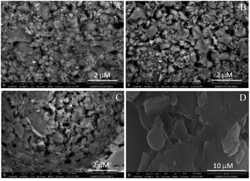 | ||
| Fig. 1 SEM micrographs of mesoporous glass–ceramic frits prepared at different sintering temperatures (frits from A to D). | ||
Nitrogen sorption experiments were conducted to evaluate the pore size distribution of glass–ceramic frits. As shown in Fig. 2, pore size distributions of glass–ceramic frits (A, B, and C) have an average pore size in the range of about 2 nm. Mesoporous glass–ceramic frits are found to have a BET specific surface area of 10.02, 18.39, and 5.9 m2 g−1 for frits A, B, and C, respectively. It was previously shown that high sintering temperatures (1200–1590 °C) led to the formation of macropores, as well as the disappearance and closing of the mesopores.13 It is worth mentioning that Pyrex–Kaolin glass–ceramic unlike alumina or zirconia-based ceramic material, could be sintered at a relatively much lower temperature (750–850 °C) without closing of the mesopores. This makes Pyrex and Kaolin a more suitable material for the preparation of ceramic frits. Mesoporous frit-based reference electrodes are expected to have a minimum flow rate and consequently could be utilized in experiments with a long-term timeframe without contaminating the sample solution (see below).
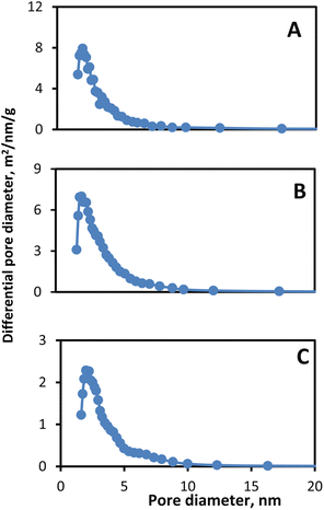 | ||
| Fig. 2 Pore size distribution of mesoporous glass–ceramic frits (A, B and C) based on BJH analysis of nitrogen sorption isotherms. | ||
Water absorption reflects the density of the ceramic frit. Water absorption can be calculated using the following equation based on (JIS A 5209) method:15,16
| Parameter | |||||||
|---|---|---|---|---|---|---|---|
| Frit type | Average pore size | Impedance, Ω | Effect of pH, mV | Flow rate, μL h−1 | Effect of KCl, mV | Potential drift, μV h−1 | |
| Mesoporous glass–ceramic (this work) | Frit A | 2.2 nm | 680 | 15 ± 4 | 0.41 ± 0.06 | 12 ± 4 | −2.4 ± 0.2 |
| Frit B | 2.4 nm | 1113 | 17 ± 5 | 0.04 ± 0.01 | 15 ± 2 | −2.1 ± 0.2 | |
| Frit C | 2.8 nm | 4880 | 12 ± 3 | 0.002 ± 0.001 | 11 ± 3 | −4.9 ± 0.2 | |
| Mesoporous polymers12 | ∼14 nm | 630–700 | 10 | 0.007 ± 0.003 | 50 | — | |
| Polyethylene9,14 | ≈10 μm | 424 ± 341 | 40 | 318 ± 279 | 5 | ∼200 | |
| Teflon micro size9,14 | ≈1 μm | 222 ± 195 | 65 | 29.3 ± 3.6 | 5 | ∼200 | |
| Electro-porous KT glass9,14 | 0.5–1 μm | 71 ± 27 | 5 | 3.8 ± 1.3 | 10 | ∼200 | |
| CoralPor9,14 | 4–10 nm | 139 ± 53 | 40 | 0.005 ± 0.003 | 50 | ∼200 | |
| Vycor8,9,14 | 4–6 nm | 69 ± 17 | 30 | 0.004 ± 0.002 | 30–150 | ∼200 | |
Measurement of the thermal expansion coefficient of glass–ceramic is useful to predict the cracking and wilding of ceramic with borosilicate glass which is a typical material for reference electrode bodies. Borosilicate glass has a thermal expansion coefficient of 3.2 × 10⁻⁶ to 4.0 × 10⁻⁶ °C−1. Ceramic and glass should have close thermal expansion coefficients for perfect welding.18 Therefore, the mesoporous glass–ceramic composite was prepared using a high content of borosilicate glass (75 w/w%). Indeed, as can be seen in Fig. S1,† the thermal expansion coefficients of mesoporous glass–ceramic frits (A–C) prepared at different sintering temperatures (4.8 × 10⁻⁶ °C−1) are found to be close to that of the borosilicate glass.
The chemical durability of glass–ceramic composite based frits was assessed using the acid solubility as recommended by API (American Petroleum Institute test procedure).17 According to API recommendations, a 5 g glass–ceramic composite is placed in a 150 ml Teflon beaker containing 100 mL of a mixture of acid solution that is composed of 12 w/w% HCl and 3 w/w% HF. The beaker containing mesoporous glass–ceramic frits and the acid mixture is then placed in a water bath for 30–35 min at 65 °C. Stirring is avoided according to API. Then mesoporous glass–ceramic frits are filtered, washed three times with 20 ml of distilled water, and dried till constant weight at 105 °C. The percentage of weight loss due to contact with acids was then calculated. The chemical durability of prepared glass–ceramic frits was found to be high with minimum solubility in acid solutions; 0.83.0.40, 0.36, and w/w%, for frits A, B, and C respectively. It could be noted that the acid solubility of glass–ceramic composites decreases with increasing sintering temperature. This could be due to increasing the degree of fusion and density, as well as the closing of the pores with increasing the temperature. Nonetheless, all prepared glass–ceramic composites (A, B, C) exhibited excellent chemical durability. Compared to other ceramics that exhibited a high acid solubility (1.6–6.9 w/w%),17 the prepared mesoporous glass–ceramic frits have much lower acid solubility. This high chemical durability the prepared glass–ceramic composites could be inherited from the chemical resistance and durability of the materials (Pyrex and Kaolin) used in their preparation.18
Characterization of mesoporous glass–ceramics as frits in reference electrodes
The performance of reference electrodes based on frit depends to a large extent on the use of an appropriate porous frit. A suitable frit should be characterized by low impedance to avoid errors in electrochemical measurements, low flow rate to allow long-term measurements and avoid sample solution contamination, high chemical durability for a long lifetime, and chemically inertness to avoid interaction with the sample solution, as well as the absence of screening effect. In the following section, the prepared mesoporous glass–ceramic composites (A–C) will be evaluated as frits for reference electrodes.Ideally, the reference electrode should also have zero impedance since a reference electrode's impedance can strongly affect the performance of potentiostats. A high impedance reference electrode can cause DC errors only if the impedance of a reference electrode gets quite high. For instance, a reference electrode with 100 kΩ causes a slight DC voltage measurement error of less than 5 microvolts (assuming input current is less than 50 pA, which is typical for modern potentiostats). This error is very small and should not affect DC voltage measurements. The situation for AC measurements is quite different and a high impedance reference electrode causes a significant error in measurements, especially in electrochemical impedance spectroscopy (EIS) performed at high frequency.19 A reference electrode with 100 kΩ impedance and a typical electrode capacitance of 5 pF has a time constant of 500 ns. This reference electrode causes a severe phase shift of about 18° at 100 kHz frequency. EIS could be performed at much higher frequencies (e.g., in the MHz range), which makes the use of a reference electrode with low impedance an essential requirement to avoid errors in measurements. A high impedance reference electrode will cause problems that range from simple overloads to oscillation of potentiostat. Therefore, impedance measurement of reference electrodes is one of the important features that should be assessed. Impedance was measured using a two-electrode system, the frequency was scanned from 0.1 to 5 kHz, and the phase angle was close to zero.
Lower flow rates require a more restrictive flow path, and restrictions could increase the resistance of the frit and there is usually a trade-off between frit impedance and flow rate. The flow rate of mesoporous glass–ceramic frits decreased with increasing the impedance of frits (Table 1). For instance, frit A with the lowest impedance (680 ± 50 Ω) in an aqueous medium has the highest flow rate (0.41 ± 0.06 μl h−1) among other mesoporous glass–ceramic frits (see data depicted in Table 1). The impedance values of mesoporous glass–ceramic frits A and B are practically comparable to that of the recently developed functionalized mesoporous polymeric frits and that of the commercially available macroporous polyethylene frits (see data depicted in Table 1). Such impedance values are within the suitable range for electrical measurements using commercially available potentiometers9 and potentiostats. While the impedance values of frits A and B are comparable with those of the previously reported mesoporous polymeric frits and the commercially available microporous polyethylene frits, frit C exhibited high impedance. Therefore, reference electrodes constructed using frits A or B are recommended in electrochemical measurements rather than frit C.
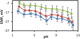
The ideal reference electrode must be pH-independent; otherwise, the potential of the reference electrode changes with changing the pH of the sample solution. The effect of pH on the responses of the mesoporous glass–ceramic frit-based reference electrodes was carried out by spiking a solution containing a 0.01 M KCl background with 0.01 M HCl and 0.5 M NaOH. As shown in Fig. 3 the pH dependence of reference electrodes prepared with mesoporous glass–ceramic frits A, B, and C exhibited 15, 17, and 12 mV variations over 10 pH units for frits A, B, and C, respectively. Such variations are much smaller than those observed for the commercially available Vycor and CoralPor reference electrodes, which exhibited 30 and 40 mV variations in reference electrode potentials, respectively, over 10 pH units when measurements are made in the same background (Table 1). Charged nanopores of the silanol groups in commercially available Vycor and CoralPor frits are the source of this heavy pH dependence due to the electrostatic screening of ion transfer into the negatively charged pores of the frit at low ionic strength.8,9 Electro-porous KT glass-based reference electrode showed much small pH dependence (5 mV over 10 pH units) (Table 1). However, the Electro-porous KT-glass reference electrode has the disadvantage of a high flow rate (3.8 μL h−1) which limits its applications in long-term experiments. The pH independence of the developed mesoporous glass–ceramic frit-based reference electrodes is comparable to that of the mesoporous monolith frit-based reference electrodes which exhibited 10 mV variation over 10 pH units (Table 1).
The decrease in the screening effect in the case of the prepared mesoporous glass–ceramic frits could be explained based on the chemical nature of Pyrex which is the major constituent of the prepared glass–ceramic composites (70 w/w%). It was reported that the electrical conductivity of Pyrex is much lower than that of silicate glasses.20 This behavior was explained based on the finding that Na+ ions are more strongly bonded to BØ4− tetrahedra with bridging oxygen than to SiØ3O− tetrahedra with nonbridging oxygen.20 Thus, borosilicate glass could be considered less charged compared to Vaycor and CoralPor glass containing only SiØ3O−. This notion was supported by the previous literature data, which indicated that the zeta potential of silicate glass is ∼−40 to −90 mV over the pH range of 2–10 as measured in an aqueous solution,21 while that of borosilicate glass is ∼−20 to −50 mV measured at the same conditions.22 The prepared glass–ceramic composite, however, exhibited a smaller zeta potential compared to its constituents in the range of −5 to −30 mV (see Fig. 4), which could account for the observed mitigated screening effect of mesoporous glass–ceramic compared to silicate-based nanoporous frits (see below). Moreover, zeta potential data of the prepared glass–ceramic composite indicate that the glass–ceramic composite has a negative surface charge at all measured pH values. The magnitude of the surface charge becomes more negative with increasing pH until the pH value reaches 7, which could be attributed to the gradual deprotonation of the silanol groups. At pH values higher than 7, however, the surface becomes slightly less negative. This could be explained based on the chemical structure of the kaolinite component of the glass–ceramic composite that contains both silica and alumina.23 Silica is either neutral or negatively charged based on the pH of the medium. Alumina octahedral face of kaolinite, however, is reported to possess either positive or negative charge as a function of the pH of the medium.23 Changing the charge type of alumina as a function of pH could account for the slight decrease in the surface charge of the glass–ceramic composite at pH > 7.
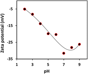 | ||
| Fig. 4 Zeta potential of glass–ceramic composite-water dispersion in solutions with different pH values. | ||
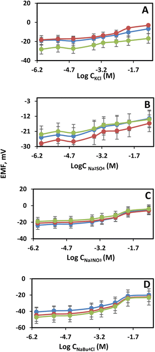
Another evidence that the developed mesoporous glass–ceramic frits trigger a smaller screening effect, compared to glass frits, is studying the effect of some representative electrolytes. The potential variations of reference electrodes equipped with glass–ceramic frits (A–C) were studied with respect to the concentration of KCl, NaNO3, Na2SO4, and NBu4ClO4 (Fig. 5A–D). Those electrolytes were chosen not only because they include many cations and anions often contained in real biological and environmental samples, but also for comparison purposes with literature data. The electrical potentials of a cell containing a reference electrode based on mesoporous glass–ceramic frits (A–C) exhibited small changes, over a wide range of electrolytes concentrations, in comparison with the previously reported mesoporous-based frits. As can be seen in Fig. 5A–D, reference electrodes equipped with different types of mesoporous glass–ceramic frits (A–C) exhibited an average potential variation of 13 ± 3 mV in case of KCl, 16 ± 1 mV in case of sodium nitrate, 10 ± 1 mV in case of sodium sulfate, and 22 ± 2 mV in case of tetrabutylammonium perchlorate over electrolytes' concentration range 1 mM to 0.1 M (Table 1). This is in clear contrast with the massive EMF changes observed for the commercially available mesoporous glass frit-based reference electrodes (up to 150 mV). Moreover, there is a 3-fold improvement in the potential variations of glass–ceramic based reference electrodes in comparison with the recently developed mesoporous polymeric frit with polyols (∼50 mV) (Table 1).
The flow rate of reference electrodes is an important feature and should be controlled to avoid intermixing and contamination of the sample and reference solutions. The flow rate must be minimized as much as possible. Fast flow-rate reference electrode requires refilling of the reference electrode solution frequently and leads to sample solution contamination. The flow through the reference electrode frit was measured at a pressure of 5 × 10⁻³ bar (pressure difference caused by filling 3.0 M KCl solution to a height of 5 cm into glass tubing attached to a porous frit). To correct for evaporation of the inner filling solution, the flow rate is measured by using two glass tubes: the first was attached to a porous frit and the second is closed at one end. The volume of solution flows through the porous frit can be obtained by measuring the difference in solution heights in both tubes. The flow rate was measured over 60 days. It was observed that as the water absorption increases, the flow rate increases with the highest flow rate for frit A (0.41 μL h−1) and the lowest for frit C (0.002 μL h−1). The flow rates for ceramic-based frits A and B are higher than the flow rates of the previously reported mesoporous frits and much lower than that of the microporous frits (e.g., Teflon, polyethylene, and KT-glass) (Table 1). However, the flow rate of glass–ceramic based frit C is 2–3-fold smaller than that reported for other mesoporous frits.
The potential drift test for reference electrodes is an essential characterization and reflects the potential stability of the reference electrode over a certain period. The potential responses of mesoporous glass–ceramic frit-based reference electrodes filled with 3.0 M KCl inner filling solutions were monitored for 50 hours in 0.10 M KCl at 25 °C (Fig. S2†). Mesoporous glass–ceramic frit-based reference electrodes constructed using frits A, B, and C exhibited improved potential stability with a very small potential drift of about −2.4 ± 0.2, −2.1 ± 0.2, and −4.9 ± 0.2 μV h−1, respectively (see data depicted in Table 1). This potential stability of mesoporous ceramic-based reference electrodes is remarkable compared to those observed for the previously reported mesoporous glass-frit-based reference electrodes (Table 1).
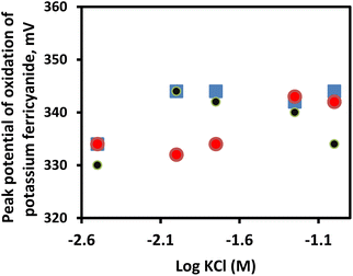
The practical utility of the prepared mesoporous glass–ceramic reference electrodes was demonstrated by performing cyclic voltammetric measurements (CVs) of potassium ferricyanide. Three-electrode set-up composed of a glassy-carbon electrode as working, a platinum wire as an auxiliary electrode, and a reference electrode was used in CVs. Fig. 6 represents the effect of the concentration of KCl (3–100 mM) on the potential of three reference electrodes based on frit-A, frit B, and free-flow. As can be seen in Fig. 6, the performances of reference electrodes equipped with frits A and B are comparable with that of the commercially available free-flow reference electrode. A variation in the peak potential of the oxidation of Fe(CN)64−, at different concentrations of KCl, in the range of about ±4–5 mV for the three tested reference electrodes was observed. The corresponding cyclic voltammograms are shown in Fig. S3A–C.† To further demonstrate that mesoporous glass–ceramic based reference electrodes are comparable to the free-flow reference electrode under the current experimental conditions, the cyclic voltammograms for 0.01 mol l−1 potassium ferricyanide as prepared in 0.1 mol l−1 phosphate buffer, pH 7 and measured at a scan rate of 100 mV s−1 are compared. As can be seen in Fig. S3D,† the three CVs have the same features with very close oxidation and reduction potentials.
Conclusions
Commercially available and low-cost Pyrex and Kaolin were utilized for the preparation of mesoporous glass–ceramic frits at relatively low temperatures. The prepared glass–ceramic frits were characterized using scanning electron microscopy (SEM), impedance measurements, and nitrogen sorption isotherms. The prepared mesoporous glass–ceramic frit exhibited high acid resistance and low-thermal expansion that enables its good adherence to Pyrex tubing. Homemade reference electrodes were constructed usingmesoporous glass–ceramic frits prepared at different temperatures. The prepared reference electrodes constructed using mesoporous glass–ceramic based frits exhibited mitigated sample-dependent properties (pH and electrolyte strength) in comparison to the heavy dependence of the previously reported reference electrodes based on mesoporous glass frits. The developed mesoporous glass–ceramic frit-based reference electrodes exhibited a potential variation, over 10 pH units, comparable to that of mesoporous polymer frit-based reference electrodes. The potential variations of the prepared glass–ceramic frit-based reference electrodes as function of electrolyte strength were enhanced by ∼3–15-fold, and ∼4-fold compared to the commercially available mesoporous glass, and the mesoporous polymeric frit-based reference electrodes, respectively. Moreover, the prepared reference electrodes exhibited superior potential stability compared to reported mesoporous frit-based reference electrodes.Author contributions
Both authors contributed to the study's conception and design. Data collection was performed by the second author. Analysis of data was performed by both authors. The first draft of the manuscript was written by the second author. Both authors read and approved the final manuscript.Conflicts of interest
There is no conflict of interest to declare.Acknowledgements
The authors would like to thank the Environmental Affairs Sector of Ain Sham University for the financial support of this work (EAS-FUND 18-19). Authors would like to thank Prof. Dr Gamal Elshafei for his helpful discussions related to zeta-potential measurements.Notes and references
- P. Buhlmann, E. Pretsch and E. Bakker, Chem. Rev., 1998, 98, 1593–1688 CrossRef PubMed.
- E. Bakker and E. Pretsch, Angew. Chem., Int., 2007, 46, 5660–5668 CrossRef CAS PubMed.
- E. Bakker and K. Chumbimuni-Torres, J. Braz. Chem. Soc., 2008, 19, 621–629 CrossRef CAS PubMed.
- G. Inzelt, A. Lewenstam and F. Scholz, Handbook of reference electrodes, Springer, Heidelberg, Germany, 2013 Search PubMed.
- A. J. Bard and L. R. Faulkner, Electrochemical methods fundamentals and applications, John Wiley and sons, New York, 2nd edn, 2009 Search PubMed.
- R. E. Dohner, D. Wegmann, W. E. Morf and W. Simon, Anal. Chem., 1986, 58, 2585–2589 CrossRef CAS.
- Gamry Instruments, https://www.gamry.com/application-notes/instrumentation/reference-electrodes/, accessed June 18, 2022.
- M. P. Mousavi and P. Bühlmann, Anal. Chem., 2013, 85, 8895–8901 CrossRef CAS PubMed.
- M. P. Mousavi, S. A. Saba, E. L. Anderson, M. A. Hillmyer and P. Buhlmann, Anal. Chem., 2016, 88, 8706–8713 CrossRef CAS PubMed.
- J. N. Israelachvili, Intermolecular and surface forces, Academic press, 2011 Search PubMed.
- W. B Russel, D. A Saville, and W. R. Schowalter, Colloidal dispersion, Cambridge University Press, Cambridge, U. K., 1989 Search PubMed.
- E. L. Anderson, S. A. Saba, D. J. Loomis, P. Buhlmann and M. A. Hillmyer, ACS Appl. Nano Mater., 2017, 1, 139–144 CrossRef.
- R. Bosch, S. Straetmans and S. Dyck, J. Mater. Sci., 2002, 37, 3973–3979 CrossRef CAS.
- E. L. Anderson, Development of improved ion-selective and reference electrodes for in situ monitoring of ion concentrations, PhD thesis, 2019, University of Minnesota, Minneapolis, USA.
- T. Kato, K. Ohashi, M. Fuji and M. Takahashi, J. Ceram. Soc., 2008, 116, 212–215 CrossRef CAS.
- A. Grandjean, M. Malki, V. Montouillout, F. Debruycker and D. Massiot, J. Non-Cryst. Solids, 2008, 354, 1664–1670 CrossRef CAS.
- O. Saad, A. N. M. Salem and I. H. Badr, Egypt. J. Chem., 2021, 64, 2193–2199 Search PubMed.
- P. Taylor, S. D. Ashmore and D. G. Owen, J. Am. Ceram. Soc., 1987, 70, 333–338 CrossRef CAS.
- F. Mansfeld, S. Lin, Y. Chen and H. Shih, J. Electrochem. Soc., 1988, 135, 906 CrossRef CAS.
- D. Ehrt and R. Keding, J. Glass Sci. Technol., Part B, 2009, 50, 165–171 CAS.
- Y. Gu and D. Li, J. Colloid Interface Sci., 2000, 226, 328–339 CrossRef CAS.
- A. Delgado, F. Gonzalez-Caballero, J. Salcedo and M. Cabrerizo, J. Dispersion Sci. Technol., 1989, 10, 107–129 CrossRef CAS.
- V. Gupta, Surface charge features of kaolinite particles and their interactions, PhD thesis, 2011, The University of Utah, USA.
Footnote |
| † Electronic supplementary information (ESI) available. See DOI: https://doi.org/10.1039/d2ra05315b |
| This journal is © The Royal Society of Chemistry 2022 |


