 Open Access Article
Creative Commons Attribution 3.0 Unported Licence
ZrO2 coated Li1.9K0.1ZnTi3O8 as an anode material for high-performance lithium-ion batteries
Jing Peng a,
Xianguang Zeng
 *ab,
Huafeng Zhuc,
Kui Xiaa,
Jing Gonga and
Kaixin Huanga
aSchool of Materials Science and Engineering, Sichuan University of Science & Engineering, Zigong 643000, China. E-mail: hnzxg1979@126.com
bMaterial Corrosion and Protection Key Laboratory of Sichuan Province, Zigong 643000, China
cLangxingda Technology Co., Ltd, Zigong, 643000, China
First published on 2nd November 2022
Abstract
The Li1.9K0.1ZnTi3O8@ZrO2 (1 wt%, 3 wt%, and 5 wt%) anode material was synthesized by doping Li2ZnTi3O8 with potassium and coating ZrO2, where the ZrO2 coating layer was prepared by citric acid and zirconium acetate, and the potassium source was KCl. When the added ZrO2 amount is 3%, the material has the most uniform size, reduced polarization, and reduced charge transfer resistance, and the specific capacity of LKZTO@ZrO2 (3 w%) was 361.5 mA h g−1 at 200 mA g−1 at the 100th cycle, which is higher than that of LKZTO, of 311.3 mA h g−1. The specific capacities of LKZTO@ZrO2 (3 w%) at 50, 100, 200, 500, and 1000 mA g−1 after 10 cycles were 424.9, 410.7, 394.1, 337.6 and 270.6 mA h g−1, indicating that LKZTO@ZrO2 (3 w%) has excellent electrochemical performance.
1 Introduction
Lithium-ion batteries (LIBs) are a new category of rechargeable batteries with a high specific capacity, high specific energy, long life, low cost, and high operating voltage, and have a wide range of application prospects. The physicochemical structure of the negative electrode active material has a decisive effect on the embedding and detachment of lithium ions, and is the carrier of lithium ions and electrons, which plays the role of energy storage and release, so the selection of anode materials is essential for good service life and charge/discharge performance of LIBs.1–14Li2ZnTi3O8 (LZTO) with a cubic spinel structure is considered a promising material in view of its non-toxicity, low cost, and high theoretical capacity. Li+ and Zn2+ occupy the octahedral position 8c in an atomic ratio of 1![[thin space (1/6-em)]](https://www.rsc.org/images/entities/char_2009.gif) :
:![[thin space (1/6-em)]](https://www.rsc.org/images/entities/char_2009.gif) 1, while Li+ and Ti4+ occupy the octahedral positions 4b and 12d respectively in an atomic ratio of 1
1, while Li+ and Ti4+ occupy the octahedral positions 4b and 12d respectively in an atomic ratio of 1![[thin space (1/6-em)]](https://www.rsc.org/images/entities/char_2009.gif) :
:![[thin space (1/6-em)]](https://www.rsc.org/images/entities/char_2009.gif) 3, so that LZTOcan also be written as (Li0.5Zn0.5)tet (Li0.5Ti1.5)oct (where tet stands for the tetrahedral position, and oct represents the octahedral position). In particular, a unique three-dimensional meshwork structure made by LiO6 and TiO6 provides a channel for Li+ transport.15,16 Compared with lithium zinc titanate, silicon in the process of lithium-ion insertion/extraction will cause Si volume expansion of 100% to 300%, generate greater internal stress inside the material, and cause damage to the material structure; the electrode material falls off on the copper foil, and the SEI film on the silicon surface is constantly repeatedly formed-ruptured-formed, which jointly reduces the conductivity and cyclic stability of the electrode. However, the ionic and electronic conductivity of LZTO is relatively poor. To improve the low electrical conductivity of LZTO, the usual modification methods used are surface coating,17–19 ion doping,20–25 and structural nanosizing.26
3, so that LZTOcan also be written as (Li0.5Zn0.5)tet (Li0.5Ti1.5)oct (where tet stands for the tetrahedral position, and oct represents the octahedral position). In particular, a unique three-dimensional meshwork structure made by LiO6 and TiO6 provides a channel for Li+ transport.15,16 Compared with lithium zinc titanate, silicon in the process of lithium-ion insertion/extraction will cause Si volume expansion of 100% to 300%, generate greater internal stress inside the material, and cause damage to the material structure; the electrode material falls off on the copper foil, and the SEI film on the silicon surface is constantly repeatedly formed-ruptured-formed, which jointly reduces the conductivity and cyclic stability of the electrode. However, the ionic and electronic conductivity of LZTO is relatively poor. To improve the low electrical conductivity of LZTO, the usual modification methods used are surface coating,17–19 ion doping,20–25 and structural nanosizing.26
Zeng et al.22 added Cr(NO3)3 to Li2ZnTi3O8 to achieve Cr3+ doping by the liquid phase process. The experimental results suggest that the discharge-specific capacities of Li2ZnTi2.9Cr0.1O8 were 156.7 and 107.5 mA h g−1 at 2 and 5 A g−1, respectively. Furthermore, even at 1 A g−1 the specific capacity remained at 162.2 mA h g−1 at the 200th cycle. The doping of Cr3+ improved the electrical conductivity of Li2ZnTi2.9Cr0.1O8, thus enhancing its electrochemical performance.
Li2ZnTi3O8@α-Fe2O3 were synthesized by Li et al.18 using a simple hydrothermal method. The Li2ZnTi3O8/α-Fe2O3 showed an irregular spherical morphology similar to that of Li2ZnTi3O8 and relatively small particle size compared to Li2ZnTi3O8. The charging capacity of Li2ZnTi3O8/α-Fe2O3 (5 wt%) was 184.8 mA h g−1, whereas the charging capacity of Li2ZnTi3O8 was 110.7 mA h g−1. The Li2ZnTi3O8/α-Fe2O3 has the benefits of a single component and exhibits new and attractive properties.
Tang et al.19 prepared Li2ZnTi3O8/La2O3 anode nanocomposites by a simple method. The high specific capacity of Li2ZnTi3O8/La2O3 was 188.6 mA h g−1 and maintained a high specific capacity of 147.7 mA h g−1 at the 100th cycle at 2.0 A g−1. Furthermore, Li2ZnTi3O8/La2O3 exhibited a retention rate of 42.7% after 1000 cycles at 2.0 A g−1, which was much higher than that of uncoated Li2ZnTi3O8. The superior lithium storage performance of Li2ZnTi3O8/La2O3 can be attributed to the stability of the protective layer, the small particle size, and the large surface area.
Zirconia is often used as a cladding material and ZrO2 is known to have three well-defined crystalline phases, namely cubic, tetragonal and monoclinic phases.27 In this paper, zirconia cladding materials were prepared using different ratios of citric acid and zirconium acetate as raw materials, lithium acetate anhydrous as lithium source, zinc acetate dihydrate as zinc source, titanium dioxide nanoparticles as titanium source, and potassium chloride as potassium source, and Li1.9K0.1ZnTi3O8 (LKZTO) was prepared by sol–gel combined with microwave sintering, and finally different amounts of ZrO2 were added to LKZTO. The LKZTO@ZrO2 anode material was obtained by coating with different amounts of ZrO2. The results showed that the electrochemical performance of the material prepared at 3% ZrO2 addition was superior.
2 Materials and methods
2.1 Preparation of LKZTO
LKZTO (0.02 mol) was prepared via the sol–gel reaction. First, TiO2 (99.8%, Maclin), (CH3COO)2Zn·2H2O (AR, Cologne Chemical), (CH3COO)Li (99.9%, Maclin), and KCl (AR, Cologne Chemical) were added to anhydrous ethanol, and the mixture was dried at 80 °C for 4 h. Then the white precursor was heated at 750 °C for 15 minutes in a microwave sintering furnace (in an Ar atmosphere) to prepared the LKZTO anode material, which named LKZTO. The preparation of LZTO is the same as the above scheme but does not contain KCl.2.2 Preparation of LKZTO@ZrO2 composite
For the preparation of LKZTO@ZrO2 composite, the prepared LKZTO was dispersed in deionized water for 30 minutes. After that, the citric acid (C6H8O7) and Zr(CH3COO)4 were dissolved in deionized water, respectively, and drop by drop into the LKZTO solution, the mixture was dried at 80 °C after sealed at 80 °C for 3 h. Then the white precursor was heated at 400 °C for 5 h in a muffle furnace. The ratios of ZrO2 in LKZTO are 1, 3, and 5 wt%, and the corresponding composites are named LKZTO@ZrO2-1, LKZTO@ZrO2-2, and LKZTO@ZrO2-3, respectively, as Fig. 1.2.3 Materials characterization
The crystal structure of the synthesized material was obtained by X-ray diffraction (XRD, Brook AXS's D2 PHASER), and the range of records is 10–70° (2θ) with CuKα radiation. The micromorphology of the materials was observed by scanning electron microscope (SEM, TESCAN VEGA3) and high-resolution transmission electron microscope (HR-TEM, Talos F200X). The Brunauer Emmett Teller (BET) surface area tests were analyzed using an ASAP2460. Surface chemical composition was recorded by X-ray photoelectron spectroscopic (XPS, Escalab 250Xi) using a K Kα excitation source.2.4 Electrochemical measurements
Electrochemical testing of anode materials was tested by a CR2032 button cell. Electrode materials were made up of active materials (80 wt%), Super P (10 wt%), and sodium carboxymethylcellulose (CMC) (10 wt%) (The loading capacity of the active material is about 1.0–1.5 mg, and the small loading amount will make the electrochemical performance of the material not be fully demonstrated, and the excessive loading amount will lead to material waste inside the material, resulting in a sharp decrease in the specific capacity of the material), then the slurry was spread on a copper foil and dried at 80 °C for 8 h in a vacuum oven. The CR 2032 button cells were assembled in an Ar-filled glove box. The constant current charge–discharge test was carried out on the LANHE CT2001A in the voltage range from 0.5 to 3.0 V (vs. Li/Li+).Cyclic voltammetry (CV) and electrochemical impedance spectroscopy (EIS) tests were recorded by CHI660E. CV tests were recorded in the voltage range from 0.05 to 3.0 V at the scanning rate of 0.1 mV s−1, and EIS tests were measured at the frequency range of 10–10 kHz. All electrochemical properties of materials were measured at temperature.
3 Results and discussion
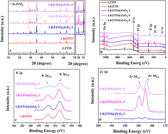
XRD patterns for LZTO, LKZTO, LKZTO@ZrO2-1, LKZTO@ZrO2-3 and LKZTO@ZrO2-5 materials are shown in Fig. 2(A). All samples have good crystallinity and belong to the cubic spinel structure, which indicates that a dose of K+ did not change the structure of the materials. It is worth noting that the 2θ degree of 28.3°, 31.5°, 33.9°, and 35.78° correspond to (![[1 with combining macron]](https://www.rsc.org/images/entities/char_0031_0304.gif) 11), (111), (002) and (
11), (111), (002) and (![[1 with combining macron]](https://www.rsc.org/images/entities/char_0031_0304.gif) 02) planes of Monoclinic-ZrO2 (m-ZrO2),28 respectively.
02) planes of Monoclinic-ZrO2 (m-ZrO2),28 respectively.
To further study, the lattice parameters of five materials are expressed in Table 1. The results indicated that the increased lattice constant of LKZTO, which may be due to a slight increase in the lattice constant due to the entry of K+ into the crystal structure, as the radius of K+ (1.38 Å) is larger compared to Li+ (0.076 Å),29 and the lattice parameters only change slightly after ZrO2 coating, means ZrO2 only coated on the surface of the LKZTO and not change the cubic spinel structure, and The addition of ZrO2 makes the particle size of the material smaller, the particle size of the material is small, and the large surface tension makes the lattice distortion and the lattice parameters become smaller. It's showing that K+ doping and ZrO2 coating widens the transport channels for lithium ions and speeds up the rate of Li+ transport, further improving the electrochemical properties of the electrode material.30
| Samples | Lattice parameters |
|---|---|
| a (Å) | |
| LKZTO@ZrO2-5 | 8.37454 |
| LKZTO@ZrO2-3 | 8.37377 |
| LKZTO@ZrO2-1 | 8.37629 |
| LKZTO | 8.37323 |
| LZTO | 8.36786 |
To prove the formation on the surface of the material, the X-ray photoelectron spectroscopy (XPS) spectrum of LZTO, LKZTO, and LKZTO@ZrO2 has shown in Fig. 2(B–D). The peaks of Li 1s, O 1s, Zn 2p, and Ti 2p appear in all samples while the peak of Zr 3d appears only in the LKZTO@ZrO2, which indicated that ZrO2 has only coated on the surface of LKZTO. In Fig. 2(C), two peaks at about 292.78 and 295.58 eV correspond well to K 2p3/2 and K 2p1/2,31 suggesting the presence of K+ in the LKZTO and LKZTO@ZrO2. The Zr 3d peak can be described as two main peaks at 182.4 and 184.8 eV corresponding to Zr 3d5/2 and Zr 3d3/2, representing the Zr4+ of ZrO2(ref. 32) (Fig. 2(D)), this is evidence that samples immersed only in Zr (CH3COO)4 have only surface Zr compared to non-immersion samples.
The SEM images of LZTO, LKZTO, and LKZTO@ZrO2 and the TEM and HRTEM images of LKZTO@ZrO2-3 are shown in Fig. 3. As seen in Fig. 3, the crystallinity of all samples is well, the particles are evenly distributed and the size is uniform. As can be seen from Fig. 3(A), the microscopic morphology of the material prepared under unmodified conditions with a diameter of about 200–300 nm; after K+ doping (Fig. 3(B)), the microscopic morphology with a diameter of about 200–300 nm. This shows that the diameter of the material does not change significantly after the doping of K+. Fig. 3(C–E) shows the SEM images of LKZTO@ZrO2-1, LKZTO@ZrO2-3 and LKZTO@ZrO2-5. From Fig. 3(C–E), it can be seen that when the zirconia addition is 1%, the size distribution of LKZTO@ZrO2-1 material is not homogeneous; when the zirconia content continues to increase to 5%, the material shows aggregation, which may be caused by too much zirconia addition; when the addition is 3%, LKZTO@ZrO2-3 were homogeneous in size, around 60–70 nm, compared to the size of 200–300 nm for LKZTO, the addition of zirconia reduced the size of the material to a great extent.
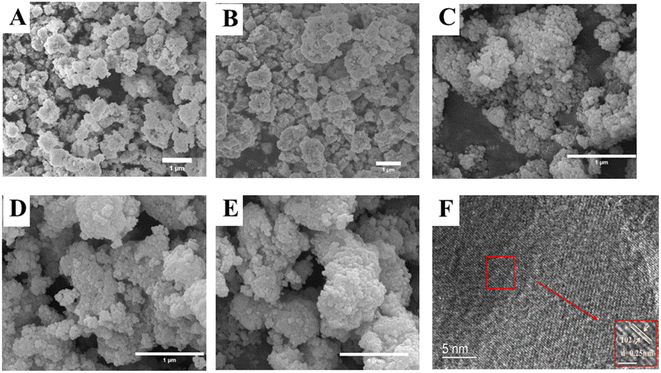 | ||
| Fig. 3 The SEM images of (A) LZTO, (B) LKZTO, (C) LKZTO@ZrO2-1, (D) LKZTO@ZrO2-3 and (E) LKZTO@ZrO2-5, HRTEM images (F) of LKZTO@ZrO2-3. | ||
The material LKZTO@ZrO2-3 with a ZrO2 addition of 3% was selected and analyzed by transmission electron microscopy. It is obvious from the TEM images that there is a layer of cladding material on the surface of the material, and the cladding layer was placed under a high-resolution transmission microscope for observation to obtain Fig. 3(F). The lattice striations of the material are evident in Fig. 3(F), indicating its good crystallinity. Calculation of the crystal plane spacing in the selected areas shows that the crystal plane spacing of the cladding layer is all 0.25 nm, which corresponds to the (![[1 with combining macron]](https://www.rsc.org/images/entities/char_0031_0304.gif) 02) crystal plane of monoclinic zirconia and is consistent with the XRD results, the peak with m-ZrO2 is detected by XRD, and the (
02) crystal plane of monoclinic zirconia and is consistent with the XRD results, the peak with m-ZrO2 is detected by XRD, and the (![[1 with combining macron]](https://www.rsc.org/images/entities/char_0031_0304.gif) 02) crystal plane with m-ZrO2 is corresponded to TEM, indicating that LKZTO@ZrO2 was successfully prepared.
02) crystal plane with m-ZrO2 is corresponded to TEM, indicating that LKZTO@ZrO2 was successfully prepared.
The specific surface area and pore diameter of LKZTO and LKZTO@ZrO2 has displayed in Fig. 4(A–D). The specific surface area of LKZTO, LKZTO@ZrO2-1, LKZTO@ZrO2-3, and LKZTO@ZrO2-5 is 24.0615, 26.8465, 27.6906, and 26.6244 m2 g−1 (relative error of ± 6% and the error was small which had little influence on the results), and it is clear that the surface area of LKZTO@ZrO2-3 is largest. The specific surface area of the material increased, which shortens the transmission distance of Li+, and reduces the charge transfer resistance and the degree of polarization. Moreover, the larger area makes the transmission of Li+ more efficient and prevents the side reaction between the electrode material and the electrolyte. Meanwhile, it can stabilize the structure and improve the material's chemical properties.
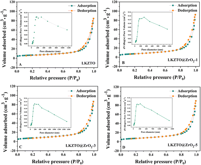 | ||
| Fig. 4 The nitrogen adsorption–desorption isotherms of (A) LKZTO, (B) LKZTO@ZrO2-1, (C) LKZTO@ZrO2-3, (D) LKZTO@ZrO2-5 and corresponding pore size distributions (inset). | ||
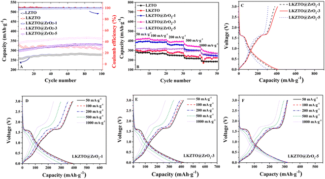
The cycling performance of LZTO, LKZTO, and LKZTO@ZrO2 was characterized at 200 mA g−1 (Fig. 5(A)) between 0.5–3.0 V. The capacity of LZTO, LKZTO, LKZTO@ZrO2-1, LKZTO@ZrO2-3, and LKZTO@ZrO2-5 is 259.1, 337.1, 300.1, 338.1 and 296.4 mA h g−1 after two cycles. At the 100th cycle, the capacity of 277.9, 311.3, 329.5, 361.5, and 326.5 mA h g−1 for LZTO, LKZTO, LKZTO@ZrO2-1, LKZTO@ZrO2-3, and LKZTO@ZrO2-5, respectively. The capacity of LKZTO@ZrO2-3 has increased means the polarization degree of the material is reduced, and the charge transfer resistance is reduced. Moreover, the transport of Li+ is more efficient, and the electrochemical performance of the material is improved.
The rate performance is an important way to evaluate the excellent electrochemical performance of a material. The material is cycled from a small current to a high current cycle, which shows whether the structure of the material will collapse due to too much current. The rate properties of LZTO, LKZTO, and LKZTO@ZrO2 are compared in Fig. 5(B). At 50 mA g−1, the capacity of LZTO, LKZTO, LKZTO@ZrO2-1, LKZTO@ZrO2-3, and LKZTO@ZrO2-5 are 283.5, 304.9, 382.8, 413.9, and 316.3 mA h g−1 at the second cycle. The specific capacities of LKZTO@ZrO2-3 after 10 cycles of 50, 100, 200, 500, and 1000 mA g−1 each were 424.9, 410.7, 394.1, 337.6, and 270.6 mA h g−1, while the specific capacities of LKZTO@ZrO2-1 after 10 cycles of 50, 100, 200, 500 and 1000 mA g−1 were 396, 387.6, 356.8, 299.2 and 244.2 mA h g−1, and the specific capacities of LKZTO@ZrO2-5 after 10 cycles of 50, 100, 200, 500 and 1000 mA g−1 were 321.1, 322, 320.2, 295, and 265.4 mA h g−1, while the specific capacities of LKZTO after 10 cycles of each 50, 100, 200, 500, and 1000 mA g−1 were 302.3, 302.7, 275.6, 250.66 and 224.4 mA h g−1, and the comparison shows that LKZTO@ZrO2-3 has the best multiplicative performance. The rate performance of the material was greatly improved after the appropriate amount of K+ doping and ZrO2 coating, probably due to:33 (1) K+ doping reduces charge transfer resistance and enhances conductivity, giving LKZTO good electrochemical properties; (2) the low dose of potassium doping broadens the Li+ transport channel, increasing the rate of Li+ transport; (3) the coating of ZrO2 can reduce the charge transfer resistance and enhance the electrical conductivity, which gives LKZTO@ZrO2-3 a good electrochemical performance; (4) the appropriate amount of ZrO2 coating makes the polarization lower and the Li+ transport efficiency higher; (5) hinder the side reaction between the material and electrolyte, the structure of the material is more stable, and the electrochemical performance of the material is improved.
Fig. 5(C) shows the charge/discharge curves of LKZTO@ZrO2-1, LKZTO@ZrO2-3, and LKZTO@ZrO2-5 at the third cycle at 50 mA g−1, (D) – (F) shows the charge/discharge curves of LKZTO@ZrO2-1, LKZTO@ZrO2-3, and LKZTO@ZrO2-5 at different current densities. From Fig. 5(C), it can be seen that the discharge-specific capacity at the third cycle of LKZTO@ZrO2-3 at 50 mA g−1 is 415.5 mA h g−1, and the third cycle, while the discharge-specific capacities of LKZTO@ZrO2-1 and LKZTO@ZrO2-5 were 385.1 mA h g−1 and 317 mA h g−1, respectively, and the comparison shows that when the addition of ZrO2 is 3%, the initial discharge specific capacity of LKZTO@ZrO2-3 is better than that of LKZTO@ZrO2-1 and LKZTO@ZrO2-5.
Fig. 5(D) and (E) show that the discharge-specific capacity of the material has a very obvious decreasing trend with the increase of current density, while graph (F) shows that its discharge-specific capacity decreases slowly with the increase of current density, which may be because when the addition of ZrO2 is 1%, although the specific capacity of the material increases, the outer layer of the material has limited ZrO2 coating, and the electrode material will have some side reactions generated with the electrolyte to consume Li+, so its specific capacity also decreases faster with the decrease of current density. When the addition amount is 3% and 5%, the ZrO2 in the outer layer of the material prevents the material from reacting with the electrolyte, which makes the material more stable and the specific capacity decreases more slowly. Therefore, when the addition amount of ZrO2 is 3%, the specific capacity can have a higher increase and also maintain a better structure under the increasing current without a rapid decrease in specific capacity, which indicated the rate capability of LKZTO@ZrO2-3 is better than that of LKZTO@ZrO2-1 and LKZTO@ZrO2-5.
The insertion of lithium ions into LKZTO involves the following processes: (1) the lithium ions dissolved in the electrolyte diffuse onto the surface of LKZTO; (2) a charge–transfer reaction occurs at the interface between LKZTO and the electrolyte, accepting both electrons from the collector and lithium ions from the electrolyte; (3) Lithium ions diffuse into the LKZTO. After coating ZrO2 could affect the processes of the charge–transfer reaction occurs at the interface between LKZTO and the electrolyte, and the lithium ions diffuse from the electrolyte to the surface of the ZrO2 coating and diffuse to the internal structure of the material through the porous structure. This will allow lithium ions to diffuse into the material more quickly through the porous structure, allowing more efficient electron transport. Obviously, a smaller particle sizes will shorten the transmission distance of Li+, and reduces the charge transfer resistance and polarization. Further, ZrO2 coating can hinder the direct contact between the electrode material and the electrolyte, reducing the probability of side reactions occurring, thereby maintaining the structural stability of the material while inhibiting the formation of SEI.
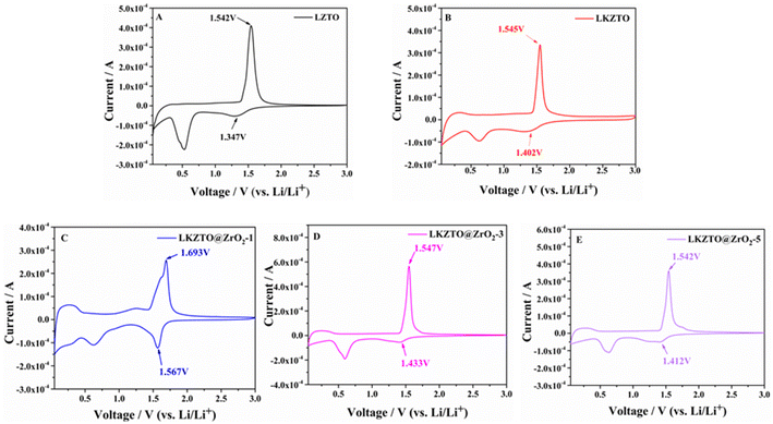
Fig. 6 shows the cyclic voltammetry curves of LZTO, LKZTO, LKZTO@ZrO2-1, LKZTO@ZrO2-3, and LKZTO@ZrO2-5, recorded at a scan rate of 0.1 mV s−1 with potentials ranging is 0.05–3 V. The peak anode potential (φPa), the peak cathode potential (φPc) and the difference between the peak anode and cathode (ΔφP) are shown in Table 2. LZTO, LKZTO, LKZTO@ZrO2-1, LKZTO@ZrO2-3, and LKZTO@ZrO2-5 all showed a pair of redox peaks in the range of 1–2 V, which corresponded to the Ti4+/Ti3+ redox process,34,35 and the shapes of the curves did not change significantly, which indicated that K+ doping and ZrO2 coating does not change the electrochemical process of LZTO.36,37 From Fig. 6, it can also be found that there is a reduction peak around 0.3–0.6 V, which may correspond to the multi-bit storage of Ti4+.37,38
| Sample | φPa (V) | φPc (V) | ΔφP (mV) |
|---|---|---|---|
| LKZTO@ZrO2-5 | 1.542 | 1.412 | 130 |
| LKZTO@ZrO2-3 | 1.547 | 1.433 | 114 |
| LKZTO@ZrO2-1 | 1.693 | 1.567 | 126 |
| LKZTO | 1.545 | 1.402 | 143 |
| LZTO | 1.542 | 1.347 | 195 |
The potential differences between the anodic and cathodic peaks of LZTO, LKZTO, LKZTO@ZrO2-1, LKZTO@ZrO2-3, and LKZTO@ZrO2-5 were 195, 143, 126, 114 and 130 mV, respectively, as shown in Table 2, which indicates that among the five materials, LKZTO@ZrO2-3 has the smallest redox potential difference of 114 mV. It is well known that the potential difference between the anodic and cathodic peaks (ΔφP) can reflect the strength of the reversibility of an electrochemical process.39,40 Therefore, LKZTO@ZrO2-3 has smaller polarization than LKZTO@ZrO2-1 and LKZTO@ZrO2-5, the transport efficiency of Li+ is increased, and the materials exhibit superior electrochemical performance properties, which are consistent with the test results of cycling performance and rate performance. Therefore, coating ZrO2 is a better way to improve the electrochemical performance of the electrode material LZTO.
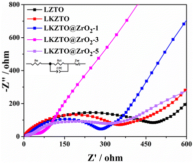
To better understand the electrochemical reaction behavior of LZTO, LKZTO, LKZTO@ZrO2-1, LKZTO@ZrO2-3, and LKZTO@ZrO2-5, EIS tests were performed on the five materials. The EIS spectra (Fig. 7.) all consist of a semicircle and a diagonal line, where the intercept of the semicircle in the high-frequency region with the X-axis represents the ohmic resistance, i.e. the contact resistance between the electrolyte and the electrode and between the electrode and the diaphragm; the semicircle represents the charge transfer resistance within the electrode and the diagonal line represents the Warburg impedance caused by the diffusion of Li+ in the active material.17,41 The corresponding equivalent circuit is shown in the inset of Fig. 7, where re represents the contact resistance in the liquid phase, Rct represents the charge transfer resistance, CPE is a constant, and Zw is the Warburg resistance.42–44 It is obvious from Fig. 7 that the charge transfer resistance of LKZTO@ZrO2-3 is the lowest, and after fitting, the charge transfer resistance of LZTO, LKZTO, LKZTO@ZrO2-1, LKZTO@ZrO2-3, and LKZTO@ZrO2-5 were 476.3, 334.5, 278.9, 68.51 and 333.7 Ω, respectively, from which it can be seen that there is a significant decrease in the charge transfer resistance of the materials after the addition of ZrO2, which indicates that the cladding of ZrO2 is an effective method to enhance the electrical conductivity and reduce the resistance. In addition, from the low-frequency region, the Li+ diffusion rate of LKZTO@ZrO2-3 is slightly higher than that of LKZTO@ZrO2-1 and LKZTO@ZrO2-5.
4 Conclusions
The LKZTO@ZrO2 (1 wt%, 3 wt%, and 5 wt%) anode material was synthesized by doping LZTOwith potassium and coating ZrO2, which the ZrO2 coating layer was prepared by citric acid and zirconium acetate, and the potassium source was KCl. From TEM and XRD can prove that the LKZTO@ZrO2 was successfully prepared, from SEM can observe that the distribution of the material is uniform, the size is uniform, and the size of the material is reduced after coating ZrO2, which is conducive to shortening the transport path of lithium ions. The specific capacities of LKZTO@ZrO2-3 after 10 cycles of 50, 100, 200, 500, and 1000 mA g−1 each were 424.9, 410.7, 394.1, 337.6, and 270.6 mA h g−1. After 100 cycles at 200 mA g−1, the capacity of 361.5 mA h g−1 of LKZTO@ZrO2-3 demonstrates that LKZTO@ZrO2 is a great anode material for high-performance lithium-ion batteries.Author contributions
Xianguang Zeng and Jing Peng: contributed conception and design of the study. Huafeng ZHU and Kaixin Huang: organized the database. Jing Peng, Jing Gong, and Kui Xia: wrote the first draft of the manuscript. Xianguang Zeng: revised the whole manuscript.Conflicts of interest
The authors declare that the research was conducted in the absence of any commercial or financial relationships that could be construed as a potential conflict of interest.Acknowledgements
This work was financially supported by the Demonstration Project of Scientific and Technological Achievements Transfer and Transformation of Sichuan Province (2021ZHCG0040).References
- Y. F. Shen, J. F. Qian, H. X. Yang, F. P. Zhong and X. P. Ai, Chemically Prelithiated Hard-Carbon Anode for High Power and High Capacity Li-Ion Batteries, Small, 2020, 16, 1907602 CrossRef CAS PubMed.
- Y. Han, L. Dong, J. M. Feng, D. J. Li and S. X. Liu, Cobalt oxide modified porous carbon anode enhancing electrochemical performance for Li-ion batteries, Electrochim. Acta, 2015, 167, 246–253 CrossRef CAS.
- K. Kim, R. A. Adams, P. J. Kim, A. Arora, E. Martinez, J. P. Youngblood and V. G. Pol, Li-ion storage in an amorphous, solid, spheroidal carbon anode produced by dry-autoclaving of coffee oil, Carbon, 2018, 133, 62–68 CrossRef CAS.
- H. Y. Bao, D. Tian, J. H. Chen and H. J. Li, Research of resin-coating natural graphite for negative electrode materials of Li-ion battery, Chin. Battery Ind., 2013, 18, 7–10+17 CAS.
- X. X. Tang, Q. S. Yang, J. W. Yang and W. W. Sun, Composite of covalent organic framework-derived nitrogen-doped carbon with carbon nanotubes for lithium-storage, J. Shanghai Univ., 2020, 26, 972–979 Search PubMed.
- R. X. Zhou and Y. Q. Ge, Preparation and electrochemical properties of carbon nanofiber anode materials, Adv. Text. Technol., 2022, 30, 41–46 Search PubMed.
- X. Q. Li, Y. F. Xing, J. Xu, Q. B. Deng and L. H. Shao, Uniform yolk–shell structured Si-C nanoparticles as a high performance anode material for the Li-ion battery, Chem. Commun., 2020, 56, 364–367 RSC.
- P. Li, J. Y. Hwang and Y. K. Sun, Nano/Microstructured Silicon-Graphite Composite Anode for High-Energy-Density Li-Ion Battery, ACS Nano, 2019, 13, 2624–2633 CAS.
- Y. X. Liu, L. J. Qin, F. Liu, Y. M. Fan, J. J. Ruan and S. J. Zhang, Interpenetrated 3D porous silicon as high stable anode material for Li-Ion battery, J. Power Sources, 2018, 406, 167–175 CrossRef CAS.
- T. Liu, H. Q. Tang, L. X. Zan and Z. Y. Tang, Comparative study of Li2ZnTi3O8 anode material with good high rate capacities prepared by solid state, molten salt and sol–gel methods, J. Electroanal. Chem., 2016, 771, 10–16 CrossRef CAS.
- Z. F. Li, Y. H. Cui, J. W. Wu, C. Q. Du, X. H. Zhang and Z. Y. Tang, Synthesis and electrochemical properties of lithium zinc titanate as an anode material for lithium ion batteries via microwave method, RSC Adv., 2016, 6, 39209–39215 RSC.
- B. K. Chen, C. J. Du, Y. Z. Zhang, R. X. Sun, L. Zhou and L. J. Wang, A new strategy for synthesis of lithium zinc titanate as an anode material for lithium ion batteries, Electrochim. Acta, 2015, 159, 102–110 CrossRef CAS.
- W. M. Long, X. Y. Wang, S. Y. Yang, H. B. Shu, Q. Wu, Y. S. Bai and L. Bai, Electrochemical properties of Li4Ti5−2xNixMnxO12 compounds synthesized by sol–gel process, Mater. Chem. Phys., 2011, 131(1–2), 431–435 CrossRef CAS.
- T. F. Yi, T. T. Wei, Y. Li, Y. B. He and Z. B. Wang, Efforts on enhancing the Li-ion diffusion coefficient and electronic conductivity of titanate-based anode materials for advanced Li-ion batteries, Energy Storage Mater., 2020, 26, 165–197 CrossRef.
- Z. X. Zhang, R. Xun, L. J. Wang and Z. H. Meng, Construction of pseudocapacitive Li2-xLaxZnTi3O8 anode for fast and super-stable lithium storage, Ceram. Int., 2021, 47, 662–669 CrossRef CAS.
- H. Q. Tang, L. X. Zan and Z. Y. Tang, Predominant electronic conductivity of Li2ZnTi3O8 anode material prepared in nitrogen for rechargeable lithium-ion batteries, J. Electroanal. Chem., 2018, 823, 269–277 CrossRef CAS.
- L. Y. Qiu, X. Q. Lai, F. F. Wang, J. J. Pan, Y. R. Zhu, P. Cui and T. F. Yi, Promoting the Li storage performances of Li2ZnTi3O8@Na2WO4 composite anode for Li-ion battery, Ceram. Int., 2021, 47(14), 19455–19463 CrossRef CAS.
- Y. Li, T. F. Yi, X. Z. Li, X. Q. Lai, J. J. Pan, P. Cui, Y. R. Zhu and Y. Xie, Li2ZnTi3O8@α-Fe2O3 composite anode material for Li-ion batteries, Ceram. Int., 2021, 47, 18732–18742 CrossRef CAS.
- H. Q. Tang, L. X. Zan, J. T. Zhu, Y. H. Ma, N. Q. Zhao and Z. Y. Tang, High rate capacity nanocomposite lanthanum oxide coated lithium zinc titanate anode for rechargeable lithium-ion battery, J. Alloys Compd., 2016, 667, 82–90 CrossRef CAS.
- P. Fu, Z. Y. Li, Y. Pan, W. B. Zeng, C. Zhu, B. M. Xu and C. Chen, Synthesis and characterization of Sm-doped Li2ZnTi3O8 as anode material for lithium-ion batteries, Mater. Chem. Phys., 2022, 227, 125449 CrossRef.
- W. Chen, Z. R. Zhou, R. R. Wang, Z. T. Wu, H. F. Liang, L. Y. Shao, J. Shu and Z. C. Wang, ChemInform Abstract: High performance Na-doped lithium zinc titanate as anode material for Li-ion batteries, RSC Adv., 2015, 46, 49890–49898 RSC.
- X. G. Zeng, J. Peng, H. F. Zhu, Y. Gong and X. Hua, Cr-Doped Li2ZnTi3O8 as a High Performance Anode Material for Lithium-Ion Batteries, Front. Chem., 2021, 8, 1–7 CrossRef PubMed.
- H. Q. Tang, Z. Y. Tang, C. Q. Du, F. C. Qie and J. T. Zhu, Ag-doped Li2ZnTi3O8 as a high rate anode material for rechargeable lithium-ion batteries, Electrochim. Acta, 2014, 120, 187–192 CrossRef CAS.
- T. F. Yi, J. Z. Wu, J. Yuan, Y. R. Zhu and P. F. Wang, Rapid Lithiation and Delithiation Property of V-Doped Li2ZnTi3O8 as Anode Material for Lithium-Ion Battery, ACS Sustainable Chem. Eng., 2015, 3, 3062–3069 CrossRef CAS.
- F. C. Qie and Z. Y. Tang, Cu-doped Li2ZnTi3O8 anode material with improved electrochemical performance for lithium-ion batteries, Mater. Express, 2014, 4, 221–227 CrossRef CAS.
- Z. S. Hong, X. Z. Zheng, X. K. Ding, L. L. Jiang, M. D. Wei and K. M. Wei, Complex spinel titanate nanowires for a high rate lithium-ion battery, Energy Environ. Sci., 2011, 4, 1886–1891 RSC.
- G. J. Wang, F. Huang, X. B. Chen, S. Wen, C. L. Gong, H. Liu, F. Cheng, X. Zheng, G. W. Zheng and M. Pan, Density functional studies of zirconia with different crystal phases for oxygen reduction reaction, RSC Adv., 2015, 5(103), 85122–85127 RSC.
- H. T. Yang, Preparation of ZrB2@ZrO2 power by in situ passivation method and the oxidation resistance of its sintered composite, Wuhan Univ. Technol., 2020 Search PubMed.
- F. C. Xi, Research on synthesis and modification of lithium zinc titanate as anode material for lithium ion batteries, Tianjin Univ., 2014 Search PubMed.
- Z. G. Tai, W. Zhu, M. Shi, Y. F. Xin, S. W. Guo, Y. F. Wu, Y. Z. Chen and Y. N. Liu, Improving electrochemical performances of Lithium-rich oxide by cooperatively doping Cr and coating Li3PO4 as cathode material for Lithium-ion batteries, J. Colloid Interface Sci., 2020, 576, 468–475 CrossRef CAS.
- H. Yang, X. H. Wang, Y. X. Qi, N. Lun, Y. M. Cao and Y. J. Bai, Improving the Electrochemical Performance of Li2ZnTi3O8 by Surface KCl Modification, ACS Sustainable Chem. Eng., 2017, 5, 6099–6106 CrossRef CAS.
- Y. Y. Zhao, Y. C. Zhang, J. Li and X. H. Du, Solvothermal synthesis of visible-light-active N-modified ZrO2 nanoparticles, Mater. Lett., 2014, 130, 139–142 CrossRef CAS.
- H. Han, F. Qiu, Z. T. Liu and X. E. Han, ZrO2-coated Li3V2(PO4)3/C nanocomposite: A high-voltage cathode for rechargeable lithium-ion batteries with remarkable cycling performance, Ceram. Int., 2015, 41, 8779–8784 CrossRef CAS.
- Z. S. Hong, M. D. Wei, X. K. Ding, L. L. Jiang and K. M. Wei, Li2ZnTi3O8 nanorods: A new anode material for lithium-ion battery, Electrochem. Commun., 2010, 12, 720–723 CrossRef CAS.
- L. Wang, L. J. Wu, Z. H. Li, G. T. Lei, Q. Z. Xiao and P. Zhang, Synthesis and electrochemical properties of Li2ZnTi3O8 fibers as an anode material for lithium-ion batteries, Electrochim. Acta, 2011, 56, 5343–5346 CrossRef CAS.
- W. Chen, H. F. Liang, L. Y. Shao, J. Shu and Z. C. Wang, Observation of the structural changes of sol–gel formed Li2MnTi3O8 during electrochemical reaction by in situ and ex situ studies, Electrochim. Acta, 2015, 152, 187–194 CrossRef CAS.
- W. J. H. Borghols, M. Wagemaker, U. Lafont, E. M. Kelder and F. M. Mulder, Size effects in the Li4+xTi5O12 spinel, J. Am. Chem. Soc., 2009, 131(49), 17786–17792 CrossRef CAS PubMed.
- H. Ge, N. Li, D. Y. Li, C. S. Dai and D. L. Wang, Electrochemical characteristics of spinel Li4Ti5O12 discharged to 0.01 V, Electrochem. Commun., 2008, 10, 719–722 CrossRef CAS.
- H. Q. Tang, J. T. Zhu, Z. Y. Tang and C. X. Ma, Al-doped Li2ZnTi3O8 as an effective anode material for lithium-ion batteries with good rate capabilities, J. Electroanal. Chem., 2014, 731, 60–66 CrossRef CAS.
- W. Chen, H. F. Liang, L. Y. Shao, J. Shu and Z. C. Wang, Observation of the structural changes of sol–gel formed Li2MnTi3O8 during electrochemical reaction by in-situ and ex situ studies, Electrochim. Acta, 2015, 152, 187–194 CrossRef CAS.
- H. Q. Tang, Study on preparation and electrochemical performance of Li2ZnTi3O8 anode materials for lithium ion battery, Tianjin Univ., 2015 Search PubMed.
- Z. Y. Kou, C. Miao, P. Mei, Y. Zhang, X. M. Yan, Y. Jiang and W. Xiao, Enhancing the cycling stability of all-solid-state lithium-ion batteries assembled with Li1.3Al0.3Ti1.7(PO4)3 solid electrolytes prepared from precursor solutions with appropriate pH values, Ceram. Int., 2020, 46, 9629–9636 CrossRef CAS.
- W. M. Long, X. Y. Wang, S. Y. Yang, H. B. Shu, Q. Wu, Y. S. Bai and L. Bai, Electrochemical properties of Li4Ti5−2xNixMnxO12 compounds synthesized by sol–gel process, Mater. Chem. Phys., 2011, 131, 431–435 CrossRef CAS.
- Y. Q. Tang, X. Liu, X. B. Huang, X. Ding, S. B. Zhou and Y. D. Chen, Synthesis and electrochemical properties of Li2FeSiO4/C/Ag composite as a cathode material for Li-ion battery, J. Cent. South Univ., 2019, 26, 1443–1448 CrossRef CAS.
| This journal is © The Royal Society of Chemistry 2022 |


