 Open Access Article
New family of layered N-based cathode materials for sodium-ion batteries†
Yundan Jiang,
Wangping Xu,
Wei Zhao * and
Juexian Cao*
Department of Physics & Hunan Institute of Advanced Sensing and Information Technology, Xiangtan University, Xiangtan, 411105, China. E-mail: zhaowei@xtu.edu.cn; jxcao@xtu.edu.cn
First published on 8th December 2022
Abstract
The cathode materials of sodium-ion batteries (SIBs) have received considerable attention not only because of their abundant natural reserves and chemical properties similar to those of lithium-ion batteries but also their great potential in energy storage and conversion technologies. However, their low capacity and high diffusion barrier remain unsolved problems. In this work, we systematically studied the theoretical capacity and sodium ion diffusion barrier in a new family of layered transition metal compounds, named MX2 (M = Ti, V, Cr, Mn, and Fe; X = C, N, and O), as the cathode materials of SIBs. The results indicate that all 2H-phase MX2 materials possess a high theoretical capacity of over 300 mA h g−1. Moreover, it is found that the 2H-phase CrN2 exhibits a desirable sodium ion diffusion barrier, indicating high mobility of sodium ions. In addition, the layered CrN2 has a remarkable voltage window (3.1–3.8 V) and outstanding electrochemical performance arising from the charge transfer between Na and N atoms, which is induced by the large electronegativity of nitrogen. Our research provides a promising candidate for application in SIB cathode materials in the future.
1. Introduction
Sodium-ion batteries (SIBs) have increasingly received attention not only because of their similar intercalation properties to lithium-ion batteries but also the wide distribution and low cost of sodium.1 Sodium-ion batteries exhibit remarkable electrochemical performance, including good cycle stability and high rate performance, which endow them with great application potential in the field of electric vehicles and large-scale energy storage.2 Cathode materials, as an important component of the sodium-ion battery, play a key role in improving battery performance and bringing down battery costs.3High-performance cathode material for SIBs calls for not only a high theoretical capacity but also good cycle stability and high-rate performance.4 Following the success of cathode materials of lithium-ion batteries, various cathode materials for SIBs have been reported, such as layered transition metal oxides, polyanionic compounds, Prussian blue analogs and organic materials.5 It is found that layered metal oxides, such as NaMO2 (M = Co, Mn, Fe),6–8 have high theoretical capacity. However, the multi-phase transition is easily induced in layered metal oxide during the charge and discharge processes, which badly hinders the diffusion of sodium ions.9,10 On the contrary, polyanionic compounds, like NaMPO4 (M = Mn, Fe, Co, Ni),11,12 have excellent cycle stability and high rate performance due to their fast sodium ion diffusion rates. But the heavy polyanions lead to a limited specific capacity.13 Experimentally, the electrochemical performance of the electrode material has been improved by ion doping9,14 and morphology control,10,15 while their intrinsically low specific capacity and sodium ion diffusion properties have not been enhanced.
Recently, transition metal dichalcogenides (TMDs), such as MX2 (M = Mo, W, Nb, Ta; X = S, Se),16–18 have attracted considerable attention due to their high theoretical capacity and graphite-like layered structure, which facilitates the intercalation and de-intercalation of sodium ions in the interlayer of TMDs.19,20 However, the phase transition and poor conductivity of TMDs impede their practical applications.21 Therefore, it is desirable to design a high-performance cathode material featuring high theoretical capacity, long cycle life and high rate performance. Some two-dimensional materials, such as monolayer ScO2 (ref. 22), BP2 (ref. 23) and V2O5,24,25 have a large specific surface area and an unrestricted sodium diffusion path, which make their excellent sodium storage capacity and diffusion properties.26 However, their generally poor conductive properties hinder the transmission of electrons. Furthermore, it is difficult for single-layer materials to achieve practical applications in sodium-ion batteries. Recently, transition metal nitrides have been fabricated experimentally,27–29 and they have also received increasing attention theoretically.30 It is shown that N-based compounds have ultra-high hardness and good electrical conductivity, especially N-based TMDs-like layered transition metal compounds with a large interlayer spacing, which is conducive to the diffusion of large sodium ions. Two-dimensional transition metal N-based materials (i.e. MoN2 (ref. 31), VN2 (ref. 32), and Zr2N33) have both high capacity and extremely fast Na diffusion performance, besides, they usually exhibit metallic features and boast good electronic conductivity, suggesting that they can serve as potential cathode SIBs materials.
Thanks to their excellent electrochemical performance, including suitable sodium ion diffusion rate, extraordinary theoretical capacity, stable structural framework, and good electronic conductivity, layered N-based TMDs-like bulk materials hold a great potential to become excellent cathode materials of SIBs. In this work, we have systematically studied the theoretical capacity and sodium ion diffusion barrier in layered bulk transition metal compounds named MX2 (M = Ti, V, Cr, Mn and Fe; X = C, N and O). Our results indicated that most of them possess high theoretical capacity and low sodium ion diffusion barrier. 2H-Phase bulk CrN2 in particular shows the lowest sodium ion diffusion barrier, revealing the high Na intercalation concentration in layered CrN2. Besides, the formation energy and phonon spectrum were also calculated to analyze the stability of layered CrN2. Plus, we also calculated the charge transfer and electronic properties. All of the results show that layered CrN2 is a desirable electrode SIBs with good electrochemical performance.
2. Computational methods
We build our calculations on Vienna ab initio simulation package (VASP),34 a first-principles calculation software package based on density functional theory (DFT), and adopt the projected augmented wave (PAW)35 method to depict the interaction between ion nuclei and valence electrons. Besides, the electron exchange-correlation is described via Perdew–Burke–Ernzerhof (PBE) functional in generalized gradient approximation (GGA).36 The long-range van der Waals interactions are depicted exactly with the DFT-D3 correction method.37,38 In this study, the cut-off energy of plane wave base expansion is set to 500 eV. The structural relaxation is geometrically optimized via the conjugate gradient (CG) method until the force on each atom is less than 0.01 eV Å−1 and reaches the energy convergence standard of 10−6 eV. For Brillouin zone sampling, the reciprocal space of the Brillouin zone is integrated with 18 × 18 × 6 M-P grid k points. Differential charge density and Bader charge analysis are used to show and measure charge transfer on atoms respectively. Band structure and density of states calculations are applied to analyze the electronic properties of materials. In the calculation of energy band structure, 140 k points are selected along the line of high symmetry points in reciprocal space. Spin polarization is taken into account in all calculations since the system contains magnetic 3d transition metal elements. Besides, the phonon spectrum is calculated via phonopy code.39To investigate the stability of materials, we compute both the formation energy and phonon spectrum of materials. The formation energy Eform is defined as the formula (1):
| Eform = (ENaMX2 − μNa − μM − 2μX)/4 | (1) |
To study the diffusion properties of sodium ions in MX2, a 3 × 3 × 1 supercell consisting of 18 M atoms and 36 X atoms is used, and a 6 × 6 × 6 K-point grid is adopted. The diffusion performance of sodium in MX2 is calculated through the climbing image nudge elastic band (CI-NEB) method.40,41 Specifically, a series of intermediate images are inserted between the optimized initial structure and the final structure, and then each image finds the lowest potential energy configuration along the reaction path. The energy and force convergence criteria of diffusion calculation are set to be 10−5 eV and 0.02 eV Å−1 respectively to improve the calculation efficiency. This method can accurately locate the diffusion path of the lowest energy and the diffusion barrier.
The theoretical capacity42 C is calculated according to formula (2):
 | (2) |
The equation for deriving voltage43 V is expressed as:
| V = −(ENax2CrN2 − ENax1CrN2 − (x2 − x1)ENa)/(x2 − x1)e | (3) |
3. Results and discussion
3.1. Screening of materials
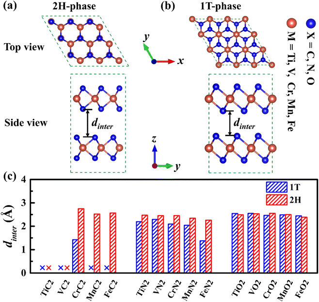
There is a sandwich-like X–M–X structure similar to TMDs in MX2, in which each M atom is coordinated with six X atoms to form a triangular prism or octahedral coordination configuration, and each X atom is coordinated with three M atoms. Due to the difference in the coordination configuration of M and the stacking period along the c-axis, the materials have several different configurations, among which 1T-phase and 2H-phase are the most common structural configurations in this type of material.44 In the 2H-phase, each M atom and six X atoms form a triangular prism, and the MX2 layer is stacked in AB order (as is shown in Fig. 1a). In the 1T-phase, each M atom is surrounded by six X atoms to form an octahedral coordination configuration, and the MX2 layer is stacked in AA order (as is shown in Fig. 1b). Therefore, a 1 × 1 × 2 supercell of 1T-phase and 1 × 1 × 1 unit-cell of 2H-phase were calculated, both of which have 2 MX2 layers containing 2 M atoms and 4 X atoms.To study the structural properties of different phases, we have fully optimized all 1T- and 2H-phase MX2, and the fully optimized structures of these MX2 are shown in Fig. S1,† and the lattice parameters of all MX2 are shown in Table S1.† The cell parameters of 2H-phase VN2 we calculated are in agreement with those of theoretically reported H-phase VN2 monolayer,45 as is shown in Table S2.† The results indicate that almost all 2H-phase MX2 maintained layered structures well, but most of 1T phase structures tend to collapse or slope, 1T-MC2 in particular. Fig. 1c gives the interlayer spacing of all 1T- and 2H-phase MX2. It is shown that most of MX2 has an interlayer spacing from 1.4 Å to 2.7 Å. However, 1T-phase TiC2, VC2, MnC2, FeC2 and 2H-phase TiC2, VC2 have no interlayer spacing because they have formed compounds. From the comparison of interlayer spacing between 1T- and 2H-phase MX2, it is obvious that most 2H-phase MX2 have larger interlayer spacing than 1T-phase. Larger interlayer spacing is beneficial to intercalation and diffusion for Na. Therefore, 2H-phase MX2 is fitter to serve as electrode materials.
To ascertain the energy stability of the NaMX2 structure, we have computed the formation energy of all 2H-phase NaMX2 systems (as is shown in Fig. 2). The results show that the corresponding nitrides and oxides have a negative formation energy while carbides have a positive formation energy, which indicates the NaMN2 and NaMO2 systems enjoy better stability than NaMC2. Better stability is beneficial to the preparation of materials. Therefore, N and O are the selected anions for its compounds whose formation energy is lower than C. Negative formation energy suggests that better cycling stability can be expected for N- and O-based compounds when they are used as the electrode materials for SIBs.
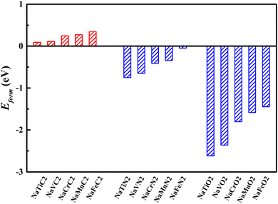 | ||
| Fig. 2 The formation energy of all 2H-phase NaMX2 systems (M = Ti, V, Cr, Mn and Fe; X = C, N and O). | ||
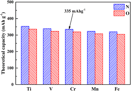
Theoretical capacity, as we know, is an important factor in the applications of electrode materials, so we have calculated the theoretical capacity of different MX2 (M = Ti, V, Cr, Mn and Fe; X = N and O) materials, and the results are shown in Fig. 3. Benefiting from the lighter relative atomic masses of 3d transition metals and 2p non-metallic elements, all MX2 (M = Ti, V, Cr, Mn and Fe; X = N and O) materials possess a higher theoretical capacity (305–353 mA h g−1). Among them, CrN2 has a theoretical capacity of 335 mA h g−1, which is much larger than traditional oxide materials46 and polyanionic compound materials47 and is nearly twice that of MoS2 (167 mA h g−1).48
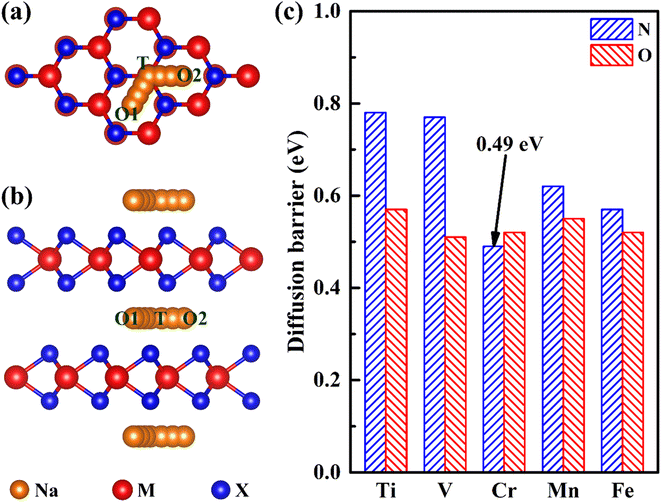
Ion diffusion is a key issue in the application of electrode materials for sodium-ion batteries. The rapid sodium diffusion determines the high-rate performance of the battery, ensuring the battery a high charge and discharge rate.49,50 Therefore, we have studied the migration properties of 2H-phase MX2 (M = Ti, V, Cr, Mn and Fe; X = C, N and O) materials. It is found that the most stable intercalation site of sodium is an octahedral gap (O1 or O2), as is shown in Fig. 3a and b. And according to the previous reporting on the migration of TMDs materials,51 the migration path of sodium is between two adjacent octahedral interstitial sites through tetrahedral interstitial sites (O1–T–O2), as is shown in Fig. 4a and b. The diffusion barrier of all Na in MX2 (M = Ti, V, Cr, Mn and Fe; X = N and O) are shown in Fig. 4c. And the diffusion energy profile along the diffusion path is shown in Fig. 5a and S2.† It is shown that all of the materials have a lower barrier. In particular, the diffusion barrier of sodium ions in CrN2 is the lowest, about 0.49 eV. Thus, CrN2 as an electrode material of sodium-ion battery boasts satisfactory rate performance.
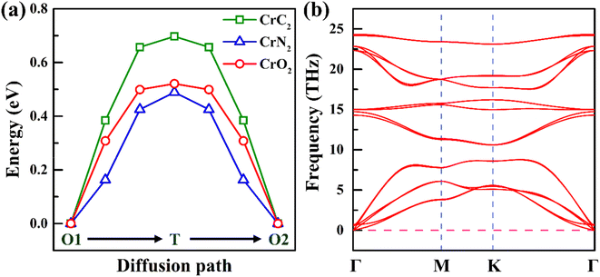 | ||
| Fig. 5 (a) Energy profile of Na diffusion along the diffusion path in 2H-phase CrX2 (X = C, N, O). (b) Phonon spectrum of 2H-phase CrN2. | ||
3.2. Properties of CrN2 as an electrode material
Due to the lowest diffusion barrier of CrN2 (0.49 eV), lower than CrC2 (0.7 eV) and CrO2 (0.52 eV), it was chosen as the best electrode material for SIBs (as is shown in Fig. 5a). To better understand the dynamic stability of CrN2 materials, we have calculated the phonon spectrum. There is no virtual frequency in the phonon spectrum (as is shown in Fig. 5b), which indicates CrN2 is dynamically stable. Thus, CrN2 possesses not only thermal stability (see Fig. 2) but also dynamical stability, which indicates a good cycling stability when it is used as electrode material for SIBs.As intercalation energy is a crucial parameter for measuring the level of difficulty in inserting sodium ions into the materials, we have calculated the intercalation energy of sodium inserting CrN2 at different sodium concentrations. It suggests that CrN2 has a large negative intercalation energy indicating the feasibility of inserting Na into it (see Fig. S3†). The most stable configurations of NaxCrN2 (x ranges from 0 to 1) at different sodium concentrations are shown in Fig. S4 in the ESI.† Fig. 6a shows the calculated intercalation energy at different concentrations. It suggests that the intercalation energy initially decreases at the concentration from 0.00 to 0.33 as the effective interaction of the sodium ions is attractive, and then increases at the concentration from 0.33 to 1.00 when the effective interaction of the sodium ions becomes repulsive. When sodium reaches the maximum concentration of 1, its intercalation energy achieves the maximum value of −3.4 eV. Overall, negative intercalation energy is conducive to sodium ion intercalated. And volume expansion rate of sodium in the process of embedding CrN2 is less than 10%, which is beneficial to the cyclic stability of the material.
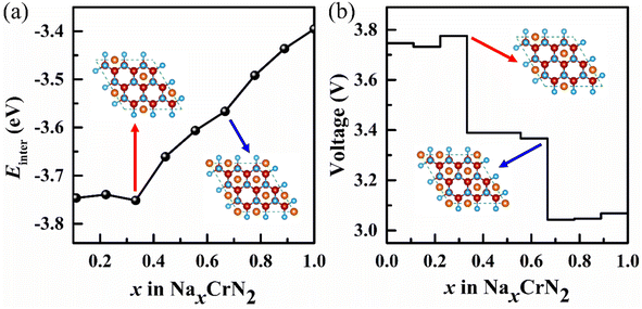 | ||
| Fig. 6 (a) Intercalation energy (Einter) of NaxCrN2 (x = 0–1) under different sodium concentrations. (b) Voltage profile under different sodium concentrations. Insets represent the intercalation configurations for NaxCrN2 (x = 0.33 and x = 0.67), respectively (red and blue arrow point to Na0.33CrN2 and Na0.67CrN2, respectively) (for more configurations at all sodium concentrations please see Fig. S4 in the ESI†). | ||
As voltage is also a critical parameter for electrode materials, we have calculated the voltage of CrN2 under different sodium concentrations. The calculated voltage is a function of sodium concentration in CrN2 (see Fig. 6b). It shows CrN2 boasts a high voltage window of about 3.1–3.8 V. Such a high voltage makes it ideal for cathode materials. When x1 = 0 and x2 = 1, the computed voltage (3.4 V) is the open-circuit voltage. Combining the open-circuit voltage and theoretical capacity, the CrN2 has a high energy density of 1139 W h kg−1, which is much higher than that of traditional cathode materials, like transition metal oxides (less than 800 W h kg−1), polyanionic compounds (no more than 500 W h kg−1) and Prussian blue analogs (about 500 W h kg−1).52
To reveal the mechanism of sodium ion intercalation, we have examined the charge transfer after sodium ion intercalated. The differential charge density is shown in Fig. S5 in the ESI.† The yellow electron-rich regions on the nitrogen atom and the cyan electron-deficient regions around the sodium atom indicate that the charge has been transferred from the sodium atom to the CrN2 substrate. Bader charge analysis calculated the number of charge transfers in great detail. The results show that the sodium atom transfer 0.73 electrons and the electrons are mainly transferred from Na to the N atom. Charge transfer means that sodium is in a cationic state, and the Na–N bond has obvious ionic characteristics. In addition, the strong sodium–nitrogen interaction further shows that sodium can be stably embedded into CrN2.
To further study the electronic structure of CrN2, we have calculated band structures and density of states, which are shown in Fig. 7. In band structure, it is shown that the CrN2 material exhibits metallic features both before and after sodium-ion intercalation, which endows it with a fast charge and discharge rate. According to the density of states near the Fermi level, the CrN2 exhibits ferromagnetism before sodium-ion intercalation in TDOS, which is mainly contributed by the Cr-d orbital electrons in PDOS. The fully sodiated state of CrN2 presents non-magnetic, and the density of N-p orbital states near the Fermi level is significantly enhanced, and the hybridization of Cr-d orbital and N-p orbital is enhanced, improving the cycle stability of the CrN2 material. In addition, the electrical double-layered structure induced by strong charge transfer between sodium and nitrogen enables the sodium-ion diffusion barrier to be reduced greatly.
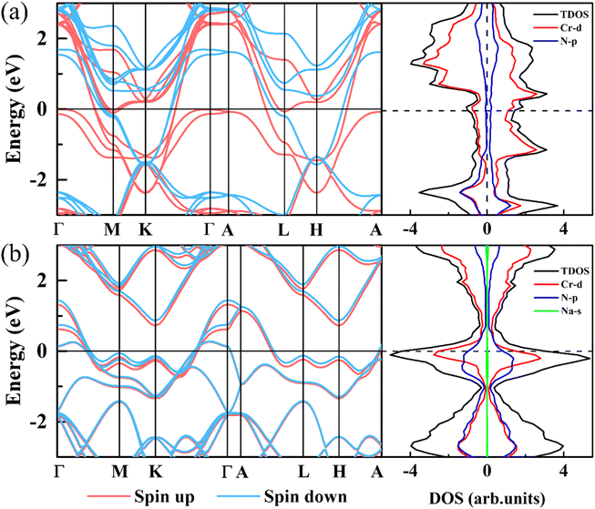 | ||
| Fig. 7 Band structure and density of states of 2H-phase CrN2 (a) and 2H-phase NaCrN2 (b), respectively. The Fermi level is set to zero. | ||
4. Conclusions
In this paper, we systematically studied the theoretical capacity and ion diffusion barrier in a new type of layered bulk transition meta compounds, named MX2 (M = Ti, V, Cr, Mn, Fe; X = C, N, O). Our results show that most of these layered MX2 materials possess a high theoretical capacity of over 300 mA h g−1. In particular, 2H-phase layered bulk CrN2 possesses a proper theoretical capacity (335 mA h g−1) and a desirable sodium ion diffusion barrier (0.49 eV). In addition, the layered CrN2 has both good thermal and dynamical stability. Importantly, the results of charge transfer and electronic properties lead to the high voltage platform from 3.1 to 3.8 V and extraordinary electrochemical performance of layered CrN2. Moreover, CrN2 boasts a high energy density of 1139 W h kg−1 thanks to its high open-circuit voltage (3.4 V) combined with high theoretical capacity. Our predicted 2H-phase layered transition-metal nitrides enjoy great potential to be ideal candidates for SIBs cathode materials.Conflicts of interest
There are no conflicts to declare.Acknowledgements
This work is supported by the National Natural Science Foundation of China (No. 11772285, 11774298, 11604278). Research Foundation of Xiangtan University (21QDZ39) and Education Department of Hunan Province (21C0093).Notes and references
- J. Y. Hwang, S. T. Myung and Y. K. Sun, Chem. Soc. Rev., 2017, 46, 3529–3614 RSC.
- Q. Bai, L. F. Yang, H. L. Chen and Y. F. Mo, Adv. Energy Mater., 2018, 8, 1702998 CrossRef.
- X. Xiang, K. Zhang and J. Chen, Adv. Mater., 2015, 27, 5343–5364 CrossRef CAS.
- L. L. Wong, H. Chen and S. Adams, Phys. Chem. Chem. Phys., 2017, 19, 7506–7523 RSC.
- J. Xiao, X. Li, K. Tang, D. Wang, M. Long, H. Gao, W. Chen, C. Liu, H. Liu and G. Wang, Mater. Chem. Front., 2021, 5, 3735–3764 RSC.
- R. J. Clément, D. S. Middlemiss, I. D. Seymour, A. J. Ilott and C. P. Grey, Chem. Mater., 2016, 28, 8228–8239 CrossRef.
- Y. J. Fang, X. Y. Yu and X. W. Lou, Angew. Chem. Int., Ed., 2017, 56, 5801–5805 CrossRef CAS.
- H. D. Luong, V. A. Dinh, H. Momida and T. Oguchi, Phys. Chem. Chem. Phys., 2020, 22, 18219–18228 RSC.
- M. Sathiya, Q. Jacquet, M.-L. Doublet, O. M. Karakulina, J. Hadermann and J.-M. Tarascon, Adv. Energy Mater., 2018, 8, 1702599 CrossRef.
- H. Xia, X. Zhu, J. Liu, Q. Liu, S. Lan, Q. Zhang, X. Liu, J. K. Seo, T. Chen, L. Gu and Y. S. Meng, Nat. Commun., 2018, 9, 5100 CrossRef.
- F. Bianchini, H. Fjellvåg and P. Vajeeston, Mater. Chem. Phys., 2018, 219, 212–221 CrossRef CAS.
- B. Senthilkumar, K. V. Sankar, L. Vasylechko, Y.-S. Lee and R. K. Selvan, RSC Adv., 2014, 4, 53192–53200 RSC.
- Q. Ni, Y. Bai, F. Wu and C. Wu, Adv. Sci., 2017, 4, 1600275 CrossRef.
- B.-K. Zou, Y. Shao, Z.-Y. Qiang, J.-Y. Liao, Z.-F. Tang and C.-H. Chen, J. Power Sources, 2016, 336, 231–239 CrossRef CAS.
- A. Gutierrez, S. Kim, T. T. Fister and C. S. Johnson, ACS Appl. Mater. Interfaces, 2017, 9, 4391–4396 CrossRef CAS.
- B.-M. Zhang, C.-B. Zhang, H. Zhang, Y.-X. Hu, Y.-S. Zhang, C. Lu, J. Li, L.-B. Kong and M.-C. Liu, Appl. Surf. Sci., 2020, 513, 145826 CrossRef CAS.
- S. Fan, X. Zou, H. Du, L. Gan, C. Xu, W. Lv, Y.-B. He, Q.-H. Yang, F. Kang and J. Li, J. Phys. Chem. C, 2017, 121, 13599–13605 CrossRef CAS.
- D. B. Putungan and J. L. Kuo, Phys. Chem. Chem. Phys., 2021, 23, 19811–19818 RSC.
- Q. Su, X. Cao, X. Kong, Y. Wang, C. Peng, J. Chen, B. Yin, J. Shi, S. Liang and A. Pan, Electrochim. Acta, 2018, 292, 339–346 CrossRef CAS.
- H. Wang, X. Lan, D. Jiang, Y. Zhang, H. Zhong, Z. Zhang and Y. Jiang, J. Power Sources, 2015, 283, 187–194 CrossRef CAS.
- M. Feng, M. Zhang, H. Zhang, X. Liu and H. Feng, Carbon, 2019, 153, 217–224 CrossRef CAS.
- Z. Liu, H. Deng, S. Zhang, W. Hu and F. Gao, J. Mater. Chem. A, 2018, 6, 3171–3180 RSC.
- X. J. Ye, J. Xu, Y. D. Guo and C. S. Liu, Phys. Chem. Chem. Phys., 2021, 23, 4386–4393 RSC.
- J. Zeng, J. Huang, J. Liu, T. Xie, C. Peng, Y. Lu, P. Lu, R. Zhang and J. Min, Carbon, 2019, 154, 24–32 CrossRef CAS.
- X. Zhao, X. Zhang, D. Wu, H. Zhang, F. Ding and Z. Zhou, J. Mater. Chem. A, 2016, 4, 16606–16611 RSC.
- N. Khossossi, W. Luo, Z. Haman, D. Singh, I. Essaoudi, A. Ainane and R. Ahuja, Nano Energy, 2022, 96, 107066 CrossRef CAS.
- K. Niwa, T. Yamamoto, T. Sasaki and M. Hasegawa, Phys. Rev. Mater., 2019, 3, 053601 CrossRef CAS.
- F. Kawamura, H. Yusa and T. Taniguchi, Appl. Phys. Lett., 2012, 100, 251910 CrossRef.
- T. Chen, E. Castanon, J. G. Gigax, H. Kim, R. Balerio, J. Fan, F. A. Garner and L. Shao, Nucl. Instrum. Methods Phys. Res., Sect. B, 2019, 451, 10–13 CrossRef CAS.
- Z. Zhao, K. Bao, F. Tian, D. Duan, B. Liu and T. Cui, Phys. Rev. B, 2016, 93, 214104 CrossRef.
- X. Zhang, Z. Yu, S.-S. Wang, S. Guan, H. Y. Yang, Y. Yao and S. A. Yang, J. Mater. Chem. A, 2016, 4, 15224–15231 RSC.
- J. Xu, D. Wang, Y. Liu, R. Lian, X. Gao, G. Chen and Y. Wei, J. Mater. Chem. A, 2019, 7, 26858–26866 RSC.
- G. Liu, S. Xu, L. Wu, J. Zhang, Q. Wang and P. Lu, Mater. Chem. Phys., 2020, 250, 123028 CrossRef CAS.
- G. Kresse and J. Furthmüller, Phys. Rev. B: Condens. Matter Mater. Phys., 1996, 54, 11169–11186 CrossRef CAS.
- P. E. Blöchl, Phys. Rev. B: Condens. Matter Mater. Phys., 1994, 50, 17953–17979 CrossRef PubMed.
- J. P. Perdew, K. Burke and M. Ernzerhof, Phys. Rev. Lett., 1996, 77, 3865–3868 CrossRef CAS.
- W. Hujo and S. Grimme, J. Chem. Theory Comput., 2011, 7, 3866–3871 CrossRef CAS PubMed.
- S. Grimme, S. Ehrlich and L. Goerigk, J. Comput. Chem., 2011, 32, 1456–1465 CrossRef CAS PubMed.
- A. Togo and I. Tanaka, Scr. Mater., 2015, 108, 1–5 CrossRef CAS.
- G. Henkelman and H. Jónsson, J. Chem. Phys., 2000, 113, 9978–9985 CrossRef CAS.
- G. Henkelman, B. P. Uberuaga and H. Jónsson, J. Chem. Phys., 2000, 113, 9901–9904 CrossRef CAS.
- D. Datta, J. Li and V. B. Shenoy, ACS Appl. Mater. Interfaces, 2014, 6, 1788–1795 CrossRef CAS PubMed.
- I. A. Courtney, J. S. Tse, O. Mao, J. Hafner and J. R. Dahn, Phys. Rev. B: Condens. Matter Mater. Phys., 1998, 58, 15583–15588 CrossRef CAS.
- Y. Wang, J. Xiao, H. Zhu, Y. Li, Y. Alsaid, K. Y. Fong, Y. Zhou, S. Wang, W. Shi, Y. Wang, A. Zettl, E. J. Reed and X. Zhang, Nature, 2017, 550, 487–491 CrossRef CAS PubMed.
- Y. Dong, Z. Tang, P. Liang, H. Wan, H. Wang, L. Wang, H. Shu and D. Chao, J. Colloid Interfaces Sci., 2021, 593, 51–58 CrossRef CAS PubMed.
- Q. N. Liu, Z. Hu, M. Z. Chen, C. Zou, H. L. Jin, S. Wang, S. L. Chou, Y. Liu and S. X. Dou, Adv. Funct. Mater., 2020, 30, 1909530 CrossRef CAS.
- S. Chakraborty, A. Banerjee, T. Watcharatharapong, R. B. Araujo and R. Ahuja, J. Phys.:Condens. Matter, 2018, 30, 283003 CrossRef.
- J. C. Su, Y. Pei, Z. H. Yang and X. Y. Wang, RSC Adv., 2014, 4, 43183–43188 RSC.
- Y. Jing, J. Liu, Z. P. Zhou, J. Zhang and Y. F. Li, J. Phys. Chem. C, 2019, 123, 26803–26811 CrossRef CAS.
- J. Liu, M. Qiao, X. Zhu, Y. Jing and Y. Li, RSC Adv., 2019, 9, 15536–15541 RSC.
- M. Mortazavi, C. Wang, J. K. Deng, V. B. Shenoy and N. V. Medhekar, J. Power Sources, 2014, 268, 279–286 CrossRef CAS.
- Y. C. Lyu, Y. C. Liu, Z. E. Yu, N. Su, Y. Liu, W. X. Li, Q. Li, B. K. Guo and B. Liu, Sustainable Mater. Technol., 2019, 21, e00098 CrossRef CAS.
Footnote |
| † Electronic supplementary information (ESI) available: The fully optimized structures of all 1T- and 2H-phase MX2 are shown in Fig. S1. The energy profile of sodium diffusion along the diffusion path in MX2 (M = Ti, V, Mn and Fe; X = C, N and O) is shown in Fig. S2. The intercalation energy for Na intercalated in 2H-phase MX2 is shown in Fig. S3. The most stable configurations of NaxCrN2 (x = 0–1) at different sodium concentrations are shown in Fig. S4. Fig. S5 shows the differential charge density of NaCrN2. Table S1 gives the lattice parameters of all MX2 systems. Table S2 gives a direct comparison of cell parameters between our predicted 2H-VN2 and theoretically reported H-phase VN2 monolayer. Table S3 gives the relaxed atomic positions of 2H-phase CrN2. See DOI: https://doi.org/10.1039/d2ra06336k |
| This journal is © The Royal Society of Chemistry 2022 |

