 Open Access Article
MnO2-based materials for supercapacitor electrodes: challenges, strategies and prospects
Juyin Liu,
Jiali Bao,
Xin Zhang,
Yanfang Gao *,
Yao Zhang
 ,
Ling Liu* and
Zhenzhu Cao
School of Chemical Engineering, Inner Mongolia University of Technology, No. 49 Aimin Street, Xincheng District, Hohhot 010051, PR China. E-mail: yf_gao@imut.edu.cn; ll@imut.edu.cn
First published on 12th December 2022
Abstract
Manganese dioxide (MnO2) has always been the ideal electrode material for supercapacitors due to its non-toxic nature and high theoretical capacity (1370 F g−1). Over the past few years, significant progress has been made in the development of high performance MnO2-based electrode materials. This review summarizes recent research progress in experimental, simulation and theoretical studies for the modification of MnO2-based electrode materials from different perspectives of morphology engineering, defect engineering and heterojunction engineering. Several main approaches to achieve enhanced electrochemical performance are summarized, respectively increasing the effective active site, intrinsic conductivity and structural stability. On this basis, the future problems and research directions of electrode materials are further envisaged, which provide theoretical guidance for the adequate design and synthesis of MnO2-based electrode materials for use in supercapacitors.
1. Introduction
In recent years, the rapid development of the global economy and the expanding industrialization of science and technology have led to the depletion of fossil energy sources and the production of large amounts of carbon dioxide emissions, which have a serious impact on the environment and human beings. In order to meet the demand for efficient energy storage systems, there is an urgent need to research and develop new electrochemical energy storage devices (EESDs) for energy conversion, which are suitable for different energy storage systems in multiple fields.1 Supercapacitors (SCs), also known as electrochemical capacitors (ECs), have attracted wide attention as they are alternative to both conventional capacitors and secondary batteries with such features as high-power density, long cyclic stability, good rate capability and fast charge/discharge.2,3 SCs have unique advantages so that make them show good perspectives for future applications in new energy technologies, such as smart and wearable electrical products, wind pitch devices and grid access systems for power grids, etc.4–7 In addition, SCs can fill the gap between batteries and conventional capacitors.1 They meet the demand for short-term acceleration in electric and hybrid vehicles by providing higher power density. The power density and energy density are represented by Ragone plot (Fig. 1).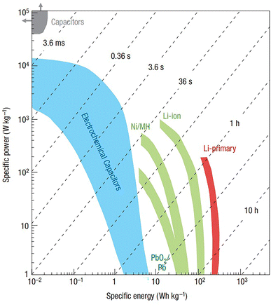 | ||
| Fig. 1 Ragone plot of different electrochemical energy conversion systems. Reproduced with permission from ref. 1. Copyright 2008, Springer Nature. | ||
Based on the energy storage mechanisms, SCs are generally defined in three major categories: electric double-layer capacitors (EDLCs), Faraday pseudo-capacitors and hybrid capacitors which are made from a combination of the above two. In EDLCs, carbon-based materials are common electrode materials, which through the adsorption and desorption of ions on the surface of the electrodes, complete the energy storage. Currently, many researchers have extensively studied carbon-based materials. Based on the traditional porous carbon materials, many new porous carbon materials have been prepared, which are able to achieve an increase in specific capacitance through the adjustment of the pore structure.8,9 However, due to the limited physical space on the surface, its obtained energy density is lower.10,11 In addition, the fast and reversible redox reacted inside the surface of electrodes in Faraday pseudo-capacitor that contribute to provide higher capacitance and increase energy density without impacting power density.12 Nevertheless, the research on the matching degree of parameters between two electrodes (positive and negative) are not mature. Hence, it requires the development of good positive and negative electrode materials with high performance and compatibility.13 In comparison, hybrid capacitors can achieve higher capacity and energy storage capability by combining two energy storage mechanisms of EDLCs and Faraday pseudo-capacitors.14
In general, the electrode materials of SCs are divided into EDLCs materials and pseudo-capacitor materials. Compared with the EDLCs materials, because of the high specific capacitance of the pseudo-capacitor materials, it plays an important role in the process of obtaining good capacitance and energy density. So far, many electrode materials based on transition metal oxides have been explored, such as TiO2,15 RuO2,16,17 V2O5,18 Co3O4,19 Fe3O4,20 MoO3 (ref. 21 and 22) and MnO2.23–26 Besides, spinel-based mixed transition metal oxides have also been investigated. Compared to the low electrical conductivity of oxides, spinel-based cobaltite has a variety of oxidation states and a higher electrical conductivity, which allows it to store more charge and thus achieve higher capacitive properties. These include FeCo2O4,27–29 ZnCo2O4,30–32 CuCo2O4,33–35 MnCo2O4,36–38 etc. MnO2 has received great attention, because of its low price, low toxicity, high theoretical capacity (1370 F g−1) and good environmental compatibility, etc.39 But the electronic conductivity and structural stability of MnO2 is poor, and there are some shortcomings such as the manganese (Mn) element is easily dissolved in the electrolyte, which limits the development and application of MnO2-based electrode materials.40 Therefore, researchers have usually worked on combining MnO2 with highly conductive substrates (e.g., metals or carbon-based materials) in order to enhance the whole performances. A series of MnO2-based composites have been designed, including MnO2/precious metal (gold, silver) composites,41–43 MnO2/transition metal (Cu, Ni, Mn) composites,44–47 MnO2/graphene composites,48–50 MnO2/carbon nanotube (CNT) composites,51,52 MnO2/porous carbon composites,53,54 etc. Up to now, MnO2-based materials have got good experiment and calculation results in aspects of enhanced electrical conductivity and improved specific surface area, and they have also been reviewed extensively from different perspectives. Our primary intention is to summarize the various engineering strategies in MnO2-based electrode materials through reference and guidance for the unique design and preparation of MnO2-based electrodes by specifically.
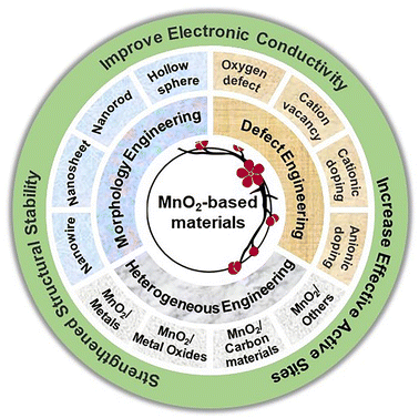
In this review, we intend to conduct an in-depth investigation and comprehensive overview of the crystal structures and energy storage mechanisms of MnO2-based electrode materials firstly. In addition, the problems which limit the application of MnO2-based electrode materials are proposed, and several examples are combined to summarize and compare different engineering strategies that can improve the performance of MnO2-based SCs (Fig. 2). Through in-depth research on improving the electrical conductivity and structural stability of MnO2, and providing effective active sites for electrolyte cations. Finally, we give the overall summary of MnO2-based electrode materials as well as the future outlook.
2. Types of MnO2 crystal structures
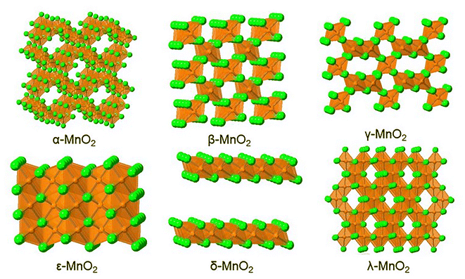
In general, MnO2 consists of [MnO6] octahedral unit, which is composed of one Mn atom and six oxygen (O) atoms. These [MnO6] octahedral units are connected to each other in different ways through shared angles and shared chains and so it shows a variety of tunnel and chain structures, which correspond to different crystal structures.55 Among them, the crystal form of MnO2 are mainly included: α-MnO2, β-MnO2, δ-MnO2, γ-MnO2, ε-MnO2 and λ-MnO2. The different crystal structures are shown in Fig. 3. According to the space structures, MnO2 can be divided into three categories: one-dimensional (1D) tunnel structures, two-dimensional (2D) layered structures and three-dimensional (3D) network structures.56The different MnO2 have different structures and space groups, as shown in Table 1. α-MnO2, β-MnO2, γ-MnO2 belong to the 1D tunnel structures where the lattice is all made up of shared chains and shared angles.57,58 α-MnO2 is a tetragonal crystal system, which belongs to the typical hollandite. It is crosslinked by the [MnO6] octahedron shared edge double chain and forms 1D (2 × 2) tunnel structure through corner connections. The tunnel size of α-MnO2 is 4.6 Å where most of the cations (e.g. K+, Li+, Na+, Mg2+, Ca2+, etc.) can be allowed to pass through for its larger tunnel. β-MnO2 is also a tetragonal crystal system with a rutile structure. The Mn atom is used as the centre of the [MnO6] octahedron, and O atoms occupy its hexagon to arrange into a single-chain angular close-packed structure. The 1D (1 × 1) tunnel structure is formed by means of shared edge connections where each chain is connected by four similar chains. The narrow tunnel of β-MnO2 is about 1.89 Å. It can only accommodate smaller ions, which is not conducive to the diffusion of ions. γ-MnO2 is a hexagonal crystal system with a hexagonal close-packed structure.59 γ-MnO2 is the result of irregular alternating symbiosis of pyrolusite (1 × 1 type) and rhodochrosite (1 × 2 type). ε-MnO2 has a structure that is comparable to γ-MnO2, and it belongs to the hexagonal crystal system as well. The former is only connected by shared planes, which leads to a disordered appearance of its lattice and the formation of an irregular tunnel structure. Mn4+ is distributed in more than half of the [MnO6] octahedral gap.60 Both δ-MnO2 and λ-MnO2 are formed by using only the shared edges of [MnO6] octahedron. δ-MnO2 belongs to the monoclinic crystal system, which has 2D layered structure formed by the common edges of the [MnO6] octahedron. It has a large interlayer distance of about 7 Å, which can allow a large number of water molecules, metal cations and other substances to pass through. Consequently, δ-MnO2 is beneficial to the migration of ions/substances. λ-MnO2 is a spinel structure, which is similar to γ-MnO2. After the irregular alternating growth of pyrolusite and rhodochrosite, it forms a 3D (1 × 1 type) network structure, which promotes charge transfer.
| Crystalline forms | Structure types | Space groups | Tunnels (n × m) | Size (Å) | Ref. |
|---|---|---|---|---|---|
| α-MnO2 | Hollandite | I4/m | (2 × 2) | 4.6 | 61 |
| β-MnO2 | Pyrolusite | P42/mnm | (1 × 1) | 1.89 | 62 |
| γ-MnO2 | Distorted boehmite | — | (1 × 1)/(1 × 2) | 1.89/2.3 | 63 |
| δ-MnO2 | Birnessite | C2/m | (1 × ∞) | 7.0 | 64 |
| ε-MnO2 | — | P63/mmc | (1 × 1)/(1 × 2) | 3D | 65 |
| λ-MnO2 | Spinel | Fd3m | (1 × 1) interconnected 3D networks | 3D | 66 |
3. Energy storage mechanism of MnO2
Electrochemical behaviors of MnO2-based electrode materials are divided into two types according to their energy storage mechanisms: EDLCs materials and Faraday pseudo-capacitance materials. The properties are determined by the cations in the electrolyte which lead to different energy storage mechanisms of MnO2-based electrode materials. For example, it usually shows pseudo-capacitive behavior in electrochemical performance tests when the charge–discharge process occurs in alkaline electrolytes or neutral electrolytes containing alkali metal ions (Li+, Na+, K+, etc.).67,68In the energy storage mechanism of EDLCs, MnO2-based electrodes exhibit adsorption/desorption activities over the material surface. After immersing the electrode in electrolyte, a tight charge layer is formed around the electrode surface by applying a certain voltage between the positive and negative electrodes, which promotes the separation of charges.69–71 But in most cases, the Faraday pseudo-capacitor energy storage mechanism is commonly used to analyze. Harnessing the variable valence states of pseudocapacitive materials to store charges. According to the differences in the thickness of MnO2-based electrode materials, it is further divided into two kinds of charge storage mechanisms for Faraday pseudo-capacitor. On the nanoscale MnO2-based electrode layers for surface charge storage. The reversible faradaic reaction on/near the electrode surface can be accomplished by adsorption/desorption of ions which from electrolyte. The process is quite similar to the physical adsorption/desorption in an EDLC, and the difference is that electrochemical reactions take place in fact. It is usually expressed by eqn (1):
| (MnO2)surface + C+ + e− → (MnO2−C+)surface | (1) |
In the formula, C+ = Li+, Na+, K+, etc. Since the electrolyte cations have opposite charges to the O atoms in the [MnO6] octahedron, and they are attracted to the O atoms and become electrically neutral during the charge/discharge. The additional generated charges are transferred to the nearby Mn atom, which results in the change of Mn4+ to Mn3+.72 Furthermore, electrolyte cations or protons can also be used for charge storage through intercalation/deintercalation in the bulk phase of MnO2-based electrode materials.73,74 Eqn (2) is expressed as follows:
| MnO2 + C+ + e− → MnOOC | (2) |
In the formula, C+ = Li+, Na+, K+, etc. Generally, the bulk pseudo-capacitive reaction is limited to the subsurface layer of MnO2, with a thickness of about 420 nm according to Brousse's study.75 Due to the thickness of the bulk MnO2-based electrode materials, the resistance to the diffusion of electrolyte cations or protons in its interior is larger. It affects the rate of ion diffusion and charge transfer, and its conductivity is poor as well. Thus, it is further illustrated that the thickness of the MnO2-based electrode materials is crucial to the capacitance.
4. Challenges of MnO2-based electrode materials
4.1 Effect of active sites on capacitance
The accommodating level of MnO2-based electrode materials for protons or cations directly determines its charge storage capacity, which affects its electrochemical performance. Generally, adjusting the size of the crystal to increase the specific surface areas is a way to obtain higher specific capacitance. For various crystal forms, the capacitance values exhibited by MnO2-based electrode materials are significantly different, which mainly depends on the size of spaces such as tunneling or interlayer spacing in the crystal structure of different dimensions. It is found that the capacitance value decreases for different crystal forms of MnO2, which following is the order: α > δ > γ > λ > β.55,76 However, due to the small proportion of effective Mn atom active centers in the crystal structure, which can attract fewer negative charges. With the increase of crystal structures and particle sizes of MnO2 of a specific phase, the electrochemical performance is reduced. Therefore, increasing the specific surface areas and exposing more effective active sites have become a necessary way to improve electrochemical performance.4.2 Influence of intrinsic conductivity on electrochemical properties
On the other hand, electrical conductivity is also one of the important factors affecting the electrochemical performance of electrode materials. Although MnO2-based electrode materials have fast and reversible redox reactions. Actually, the capacitance results of pure phase MnO2 is only 14–43% of the theoretical capacity can be achieved. This phenomenon may be due to the electrons/ions transport via the MnO2 electrode|electrolyte interface is relatively slow. Besides, the internal resistance is relatively large during the process of charging and discharging, which seriously reduces its rate capability.77 The conductivity of MnO2-based electrode materials is determined by its own inherent structural properties, which make the actual capacity far from the theoretical capacity. However, the semiconductor property can determine the internal structural properties of MnO2, and its band gap is 0.25 eV. Therefore, to obtain better electrochemical performance, MnO2 must reduce its band gap to favor metal characteristics. Hence, the key to improving the electrical conductivity of MnO2-based electrode materials lies in how to improve the limited electron transfer on the surface and the interior, that is, change its electronic properties.4.3 Effect of crystal structure on cyclic stability
Finally, the structural stability as another important factor in evaluating the performance of electrode materials to determine the cyclic stability of the materials. In all electrode materials which involving MnO2, the unavoidable disproportionation reaction of Mn element causes the problem that Mn always dissolves slowly in the electrolyte.78 The role of Mn atoms is to absorb excess charges, because the reduction of Mn leads to a decrease in the storage capacity of charges and affects the final cyclic stability of the materials. The size of the ions in the electrolyte and the spatial structure of the MnO2 are not match. The crystal structure of MnO2 expands and collapses when protons or cations are inserted or extracted, respectively. Consequently, it is urgent to improve the structural stability of MnO2.5. Engineering strategies to improve electrochemical performance
In view of the above challenges faced by MnO2-based electrode materials, researchers have proposed methods such as morphology control, introduction of defects or doping of various elements, and construction of heterostructures to improve certain properties of MnO2 to achieve the improvement of its overall electrochemical performance.5.1 Morphology engineering
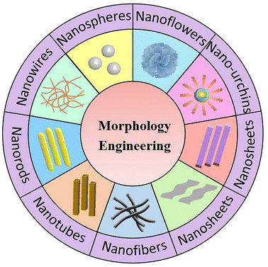
Morphology engineering is a common strategy to regulate the specific surface area of electrode materials. Larger specific surface area can be achieved by controlling the morphology of electrode materials and obtained to promote its electrochemical performance. Since the size of MnO2 grains is inversely proportional to its electrochemical performance in a certain range, and it is of great significance to synthesize nanoscale MnO2-based electrode materials. In the past period of time, many MnO2-based nanomaterials with different morphologies have been studied, and they have been designed and prepared by various synthetic methods. After a large number of experiments and literature review, we have summarized the existing morphologies of MnO2-based materials. Various forms of nanomaterials exist, including zero-dimensional (0D), 1D, 2D and 3D nanomaterials according to the spatial dimension, such as nanospheres, nanowires, nanorods, nanotubes, nanofibers, nanosheets, nanobelts, nano-urchins and nanoflowers (Fig. 4).Well-constructed nanostructures can effectively shorten the diffusion distance of ions to the electrode surface and the transport path of electrons. For example, Singu et al.79 prepared MnO2 films grown on stainless steel substrates by using the sequential ionic layer adsorption and reaction method (SILAR). Three samples were synthesized according to the cycle numbers of SILAR. With the increase of cycle numbers, the diameter of the MnO2 structure enlarged, which resulted in the change of nanoparticles into nanospheres (Fig. 5a–c). A thin film consisting of MnO2 nanospheres in the form of α-MnO2 and λ-MnO2 co-existing was created eventually. The curves of the samples showed a typical triangular shape after charging and discharging tests when the diameter of MnO2 nanospheres was 5–20 nm (Fig. 5d and e). It obtained specific capacitance up to 262 F g−1 and better capacitance retention in Na2SO4 solution (Fig. 5f). It could be concluded that nanoparticles with certain porosity were favorable for the diffusion of electrolyte ions. Tang et al.80 obtained MnO2 nanomaterials with different morphologies by changing the hydrothermal reaction times under the mild conditions. The results indicated that the morphology of MnO2 nanomaterials depended on the hydrothermal time. When the time of hydrothermal heating was increased, the MnO2 crystallinity increased gradually. And this leads to the morphology changed from the initial nanowhisker spherical to α-MnO2 nanorods. It led to an increase in the pore volume of α-MnO2, and the specific surface area was also changed from 89 m2 g−1 to 119 m2 g−1. The better specific capacitance (152 F g−1 at 2.5 mA) was displayed when the hydrothermal time was 6 h, which had good cyclic stability. In a word, changing the hydrothermal time is beneficial to change the nanoparticles to a single nanorod structure with higher specific surface areas, which contributed to better entry of electrolyte ions to obtain higher capacitance. Yin et al.81 reported a facile hydrothermal route for the synthesis of uniform and ultralong α-MnO2 nanowires in a controllable redox reaction. Based on the nanomaterials obtained, it has many less porous with a size of ∼3.8 nm. The current density of 1 A g−1 showed a specific capacitance of 180 F g−1, and the capacitance retention was above 78% after 2000 cycles. α-MnO2 nanowires with large specific surface area and small porosity shorten the diffusion paths of electrons and ions, thereby enhancing the electrochemical performance of SCs.
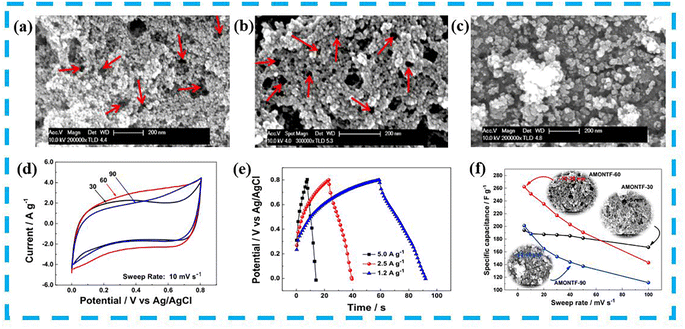 | ||
| Fig. 5 Morphology of (a) sample 1, (b) sample 2 and (c) sample 3 prepared by SILAR method. (d) Comparative cyclic voltammetry (CV) of the three samples (e) The galvanostatic charge/discharge (GCD) curves of sample 2. (f) Specific capacitance of three samples with effect on scanning rate. Reproduced with permission from ref. 79. Copyright 2016, Elsevier B.V. | ||
Xu and co-workers82 synthesize highly loose mesoporous clusters of hollow spheres and sea urchin-structured α-MnO2 nanomaterials in a simple hydrothermal method through the “Ostwald ripening process”. Among them, the shell of the hollow sea urchin was composed of densely arranged nanorods with consistent diameter and length, and the hollow sphere was composed of nanosheets. Due to its high specific surface area, it provided good cycling capability and high rate capacity. Xie et al.83 developed a self-supporting material which composed of interconnected δ-MnO2 nanosheets on graphite paper (GP). It demonstrated excellent specific capacitance (446 F g−1 at 1 A g−1) and outstanding cyclic stability under a wide voltage window of 1.3 V. Owing to the interaction which between δ-MnO2 and the open nanosheet structures interconnected with the GP substrates, the effective contact of the electrolyte was promoted. It increased the specific surface area and improved ion diffusion and charge transfer.
We also investigated the morphology of pure phase MnO2 materials. MnO2 with different morphologies was obtained by changing the hydrothermal temperature and reaction time under the condition of using the same precursor. For example, it was found that the obtained one-dimensional MnO2 micro-particles showed a “moss”-like uniform distribution (Fig. 6a). However, the MnO2 samples existed in the form of “dendritic” nanorods and packed together to form clusters when both the hydrothermal temperature and time were increased (Fig. 6b and c). And its electrochemical performance was better with a specific capacitance of 257 F g−1 at 1 A g−1 when hydrothermally reacted at 160 °C for 12 h (Fig. 6d and e).
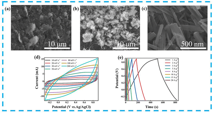 | ||
| Fig. 6 SEM images of (a) sample 1 (10 μm), (b) sample 2 (10 μm) and (c) sample 2 (500 nm). (d and e) CV and GCD curves of sample 2. | ||
Generally speaking, the pseudo-capacitance properties of MnO2 lead to a fast and reversible redox reaction, mainly between Mn(IV) and Mn(III). It enters protons and electrons into the lattice during the charging process, which means that the electrons released from the negative electrode enter the lattice of MnO2 and reduce Mn4+ to Mn3+. At the same time, the protons in the solution combine with O2− in the lattice to become OH−. Thus, for every electron and proton gained, one MnO2 molecule is converted to MnOOH. The positive MnOOH releases H+ to convert MnO2. Athouël et al.84 doped Mg in layered MnO2 and investigated in depth the effect of cycling processes on the crystal structure of MnO2 by voltammetric behavior and XRD analysis. The results show that Mg as a dopant promoted the charge transfer process and that the charging and discharging process does not change the monoclinic structure of a classic Na-birnessite.85 Therefore, the cycling process does not affect the crystal structure of MnO2. The main reason for changing its structure is the size of the cations during the intercalation/deintercalation process. When the diameter of the embedded cation is smaller than its structural tunnel, the structure does not change before and after cycling. Suppose the diameter of the cation is larger than the structural tunnel. Its structure is disrupted during the intercalation of the cation into the crystal structure, resulting in an extremely rapid decrease in capacitance. In addition, the morphology of MnO2 is more macroscopic than the valence and structure; therefore, the cycling process does not affect it significantly.
The MnO2 structure changes fundamentally with increasing spatial dimensionality. A variety of morphologies are designed and composed, and the advantages of dimension control can be used to improve the shortcomings of one or several aspects of MnO2-based electrode materials. Changing the morphology of electrode material, the higher porosity can be obtained to facilitate the diffusion of ions and electrons, or a larger specific surface area can be designed to expose more abundant active centers. This leads to further improvement of the electrochemical performances of MnO2 nanomaterials in SCs.
5.2 Defect engineering
Due to the inherent internal limitations of the material, it is sometimes impossible to solve the existing problems with simple external modifications. Defect engineering is considered to be able to adjust the electronic structure of materials effectively, and the introduction of defects in MnO2-based materials can provide them with new electronic, magnetic and optical properties.86,87 According to the mechanism of defect formation can be grouped into interstitial defects, substitutional defects, atomic vacancies and high-dimensional defects.88 This section focuses on common defect engineering strategies for MnO2-based materials: (1) oxygen vacancies, (2) cation vacancies, (3) cation doping and (4) anion doping.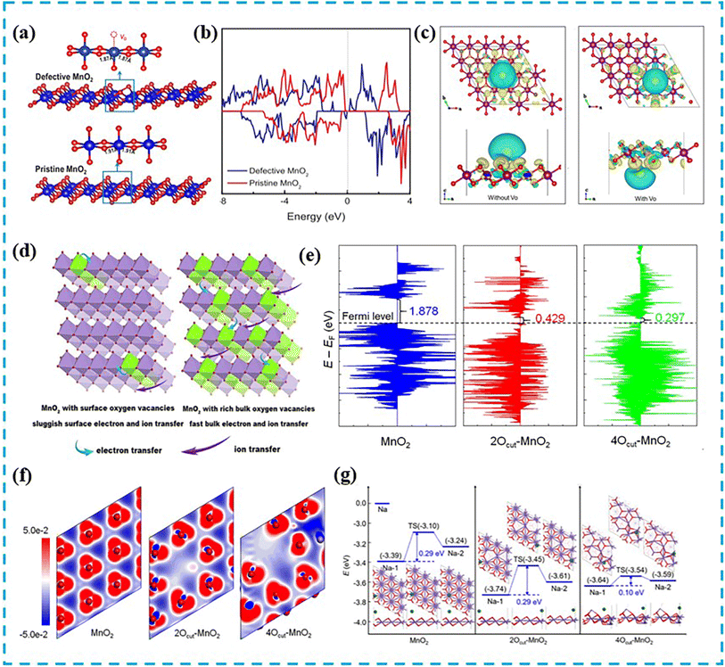 | ||
| Fig. 7 (a) Constructed models of defective and perfect δ-MnO2 surfaces. (b) Projected DOS of δ-MnO2. Reproduced with permission from ref. 89. Copyright 2019, Elsevier Ltd. (c) Difference in electron density of MnO2 without VO and with VO, blue and yellow represent charge consumption and accumulation (the Mn, O and Na atoms in purple, red and gold, respectively). Reproduced with permission from ref. 13. Copyright 2022, Elsevier B.V. (d) Charge transfer kinetics on MnO2 with surface containing VO and abundant bulk VO. (e) DOS of MnO2, 2Ocut–MnO2 and 4Ocut–MnO2 models. (f) Charge density difference between three models, with red and blue regions representing the accumulation and depletion of charge density, respectively. (g) Diagram of the energy distribution of Na+ diffusion on three models and the related structures of the intermediate, with the potential obstacles in blue (green, purple and red represented Na, Mn and O, respectively). Reproduced with permission from ref. 90. Copyright 2021, Elsevier B.V. | ||
Recently, Zhang et al.90 successfully introduced abundant VO into the bulk MnO2 phase by complex-induced chemical precipitation. MnO2 with abundant bulk VO exhibited fast charge transfer kinetics (Fig. 7d). The electronic properties of MnO2 were investigated via DFT calculations, and the results showed that VO could induce a reduction significantly in the band gap to enhance the conductivity. The concentration of VO was proportional to the conductivity (Fig. 7e). Charge density difference calculations evidenced that electrons around O and Mn atoms were accumulated and depleted, respectively (Fig. 7f). Bader charge analysis showed that with increasing concentration of VO, there was a greater electron transfer and a higher electron delocalization, which resulted in positive and negative region at VO and around O, respectively. The adsorption energy of Na+ belonged to VO-rich MnO2 in the electrolyte was stronger than that of MnO2 without VO, which proved the presence of VO was beneficial to the storage of Na+. The barrier of 4Ocut–MnO2 (0.10 eV) was lower than that of MnO2 (0.29 eV) and 2Ocut–MnO2 (0.29 eV), which demonstrated that 4Ocut–MnO2 had a fast Na+ transfer capability (Fig. 7g). At the same time, other reports had pointed out that the Mn 3d orbital state in MnO2 with VO was closer to the Fermi level and the state was more defined than that of MnO2 without VO. It was shown that VO promoted the delocalized movement of nearby electrons to the vicinity of the low-coordinated Mn atom, causing the rapid transfer of the delocalized electrons into the conduction band and improving the overall conductivity of the system.91 Thus, abundant bulk VO could increase the conductivity significantly by reducing the band gap and increasing the electron delocalization. Furthermore, a strong local electric field was formed around VO, which could accelerate bulk ion transfer with a low diffusion energy barrier. In order to enhance the energy storage capacity of MnO2 effectively. Jing et al.92 synthesized microsphere electrode materials using a typical hydrothermal-electrostatic self-assembly method combined with heat treatment. Based on in situ characterization techniques and DFT calculations, the pseudocapacitive behavior of K+ intercalation during discharge was revealed. As the amount of K+ intercalation increased, the length of the Mn–O bond near K+ in the [MnO6] octahedral structure became longer, which led to a decrease in its stability. As a result, the Mn–O bond lost O and generated VO, so that the phase transition occurred and layered MnO2 was transformed into a stable spinel-type Mn3O4.
Our research group had also successfully modified MnO2 materials by means of VO. After the method of low temperature calcination, MnO2 containing a certain amount of VO was obtained by calcining at 300 °C for 4 h. In addition, the structure of CeO2-coated MnO2 was also formed through the additional introduction of Ce3+ ions. During this process, the morphology changed from nanorods to clusters formed by aggregation of nanospheres, and VO also increased by 9.36% compared with the previous MnO2. Therefore, the charge transfer resistance of the finally obtained material was reduced, and the electrochemical performance of the corresponding material was improved.
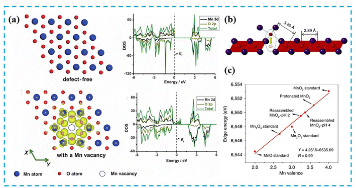 | ||
| Fig. 8 (a) The charge density distribution and density of states of MnO2 plates without Mn vacancy and with one Mn vacancy in 4 × 4. Reproduced with permission from ref. 94. Copyright 2015, Wiley-VCH. (b) Empirically estimated Mn vacancy concentration (circles) using Gaussian peak and linear baseline. (c) Average oxidation state of Mn from K-edge energies for δ-MnO2 samples and standards obtained in different pH values. Reproduced with permission from ref. 95. Copyright 2017, Springer Nature. | ||
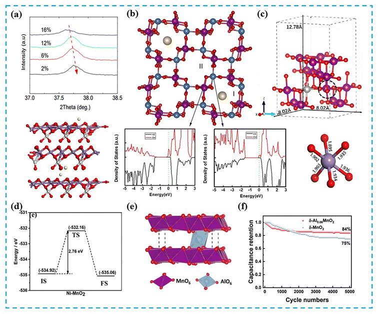 | ||
| Fig. 9 (a) The magnification of the (211) crystal plane in the XRD spectra of K+-doped MnO2 at different doping concentrations. (b) K+-doped two different Mn sites combined with the vertex and plane positions of the octahedral O in the MnO2 crystal structure (blue and purple) and effects on PDOS. Reproduced with permission from ref. 96. Copyright 2015, Springer Nature. (c) The theoretically optimized structural model of Ni–MnO2 and the magnified Mn–O bond length from the unit cell in the black circle. The purple, red and silver spheres represent the Mn, O and Ni atoms, respectively. (d) In Ni–MnO2 illustration of Na+ migration pathways and corresponding potential barriers. Reproduced with permission from ref. 97. Copyright 2022, Elsevier B.V. (e) The most stable structure of δ-Al0.06MnO2. (f) Capacitance retention of δ-MnO2 and δ-Al0.06MnO2 when the current density is 10 mA cm−2. Reproduced with permission from ref. 67. Copyright 2022, Royal Society of Chemistry. | ||
Our research group also modified MnO2-based materials by cationic doping. We have studied a variety of cationic doping, such as Ni, Co, Ce, Bi, etc. Among them, Ni, Co doping and Ce, Bi doping belong to substitution doping and interstitial doping, respectively. It was found that appropriate doping was beneficial to the improvement of the electrochemical performance of MnO2, which was consistent with the results in the literature. However, not only the performance of MnO2 could not be improved, but also the overall test results would be affected when the doping amount was slightly larger.
After experiments and research, it was found that defect engineering can change the internal structure of the MnO2 lattice to a certain extent and improve its electronic structure. Using this strategy can achieve the improvement of electronic conductivity effectively, so as to achieve the purpose of improving the electrochemical performance of MnO2.
5.3 Heterojunction engineering
Currently, the construction of heterojunctions is one of the most common methods for developing electrode materials. Manipulate electronic structure, enhance electronic/ionic conductivity, facilitate charge transfer kinetics, build porous structures, and improve structural stability by combining with other species.100–102 So, heterojunction engineering is also one of the most effective strategies to improve the adsorption and electrochemical performance of MnO2-based materials. Recently, many MnO2-based heterojunction materials for energy storage have been extensively reported.For example, Luo et al.103 utilized magnetron sputtering to synthesis the 3D network of nanofibres coated with gold on the surface. It could provide a large specific surface area and high porosity to improve the overall electrochemical performance of the material when MnO2 was electrodeposition on the conductive networks. In another example, Khandare et al.104 used gold nanoparticles to modify the surface of MnO2 nanowires (Fig. 10a). Through surface functionalization and the increase of defects, the gold nanoparticles which decorated on MnO2 nanowires provided good contacts for MnO2, so that led to larger surface area and better storage capacity. The obtained cyclic stability of MnO2 nanowires decorated with gold nanoparticles were better than MnO2 nanowires (Fig. 10b). Deng et al.47 constructed a 3D macroporous Mn core–shell structure through anodization process (Fig. 10c). Due to the high conductivity of the Mn layer, it was able to provide electron channels for charge storage and discharge (Fig. 10d). Moreover, Kumar et al.44 reported the synthesis of nanoporous MnO2–Cu structures by a facile method utilizing surface deformation and selective dealloying in the Cu–Mn system (Fig. 10e). The severe surface deformation before selective dealloying led to the in situ growth of nanoporous MnO2 in the Cu-rich matrix, which enhanced the reaction kinetics. Furthermore, the nanoporous MnO2–Cu structure provided a unique microstructure to ensure high specific surface area and small charge transfer resistance.
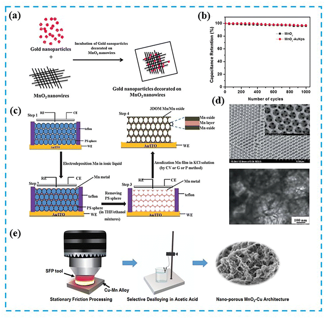 | ||
| Fig. 10 (a) Illustration showing the steps in the process of MnO2 nanowires decorated with gold nanoparticles. (b) Cyclic stability of MnO2 nanowires decorated with gold nanoparticles. Reproduced with permission from ref. 104. Copyright 2017, Elsevier B.V. (c) Fabrication of highly porous 3D ordered macroporous Mn/Mn oxide electrodes. (d) SEM image (inset: partially enlarged) and TEM image of the inverse opal Mn with structure of 3D macro-porous. Reproduced with permission from ref. 47. Copyright 2013, Royal Society of Chemistry. (e) Development process of nanoporous MnO2–Cu structures. The process included alloy synthesis by using an electric arc furnace, and severe surface deformation by using fixed friction machining and selective dealloying. Reproduced with permission from ref. 44. Copyright 2021, Elsevier Ltd. | ||
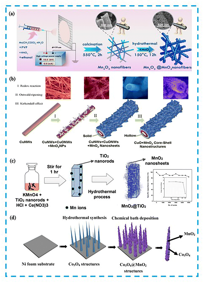 | ||
| Fig. 11 (a) Diagram of the formation of Mn2O3/MnO2 nanofibres. Reproduced with permission from ref. 105. Copyright 2020, American Chemical Society. (b) Schematic diagram of the growth mechanism of CuO/MnO2 core–shell structure. Reproduced with permission from ref. 107. Copyright 2014, Springer Nature. (c) Schematic of formation TiO2/MnO2 core–shell structure, the inset shows the cycling stability of TiO2/MnO2 constructed ASC. Reproduced with permission from ref. 109. Copyright 2020, Elsevier B.V. (d) Diagram representation of the growth of 3D Co3O4/MnO2 heterostructures grown on nickel foam. Reproduced with permission from ref. 111. Copyright 2016, Royal Society of Chemistry. | ||
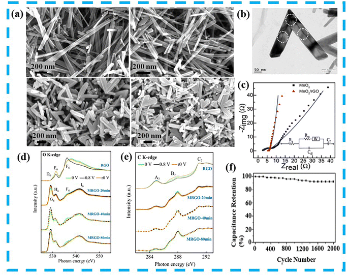 | ||
| Fig. 12 (a) FESEM images of α-MnO2 synthesized with different concentrations of acetic acid. (b) SEM image of V-shaped MnO2 nanorods. (c) Energy quist plots for the comparison of MnO2 and MnO2/rGO in the frequency range of 0.01 Hz to 0.1 MHz. Reproduced with permission from ref. 116. Copyright 2021, Royal Society of Chemistry. (d) Ex situ XAS at the O K-edge of RGO and MRGO at different times under sequential application of potentials of 0, 0.8 and r0 V. (e) Ex situ XAS at C K-edges of RGO and MRGO at different times under sequential application of potentials of 0, 0.8 and r0 V. Reproduced with permission from ref. 117. Copyright 2022, Elsevier B.V. (f) Cyclic stability of the electrode at a current density of 0.2 A g−1 for GCD. Reproduced with permission from ref. 118. Copyright 2020, AIP Publishing. | ||
Carbon Quantum Dots (CQDs) are considered as promising active nanomaterials due to their unique specific surface area, good water dispersibility and electrical conductivity.119 CQDs exhibit excellent electrochemical performance when combined with pseudocapacitive materials. Lv et al.120 fabricated ultralong MnO2 nanowires via a CQD-induced process (Fig. 13a). The formed CQD/MnO2 films exhibited superhydrophilicity in aqueous solution, which significantly improved the wettability between electrode and electrolyte (Fig. 13b). The obtained electrode material showed high specific capacitance, good reversibility and good stability. Prasath et al.121 prepared CQDs-coated MnO2 nanostructures by using waste yogurt (Fig. 13c). It had excellent electrochemical performance due to its excellent electrical conductivity, extremely small size and carrying a variety of functional groups on its surface. In addition, carbon nanotubes (CNTs) also had higher electrical conductivity and controllable specific surface areas. Li et al.122 prepared 3D CNTs by large-area ultrasonic spraying of the surface, and the 3D CNTs provided sufficient sites for MnO2 nanoparticles. High specific capacitance and good cycling stability were obtained through the good dispersion of MnO2 on the CNTs surface. Gueon and co-workers123 synthesized core–shell structures of CNTs coated with MnO2 nanosheets (Fig. 13d). Because of the stronger binding of MnO2 nanosheets on the CNT surface, this led to their low interfacial resistance. And the radial growth of MnO2 nanosheets made the existence of radial spaces between the layers on the spherical CNTs particles, which enhanced the ion diffusion to obtain high capacitive performance (370 F g−1 at 0.5 A g−1). Activated carbon (AC) is also commonly used for hybridization with transition metal oxides. Choi et al.24 used a simple hydrothermal method to synthesize AC/MnO2 composites with different mass ratios. The study found that the addition of MnO2 could improve the electrochemical performance of AC within a certain range. However, with the increase of MnO2 addition led to the decrease of porosity, which further made the electrochemical performance of the composites decreased.
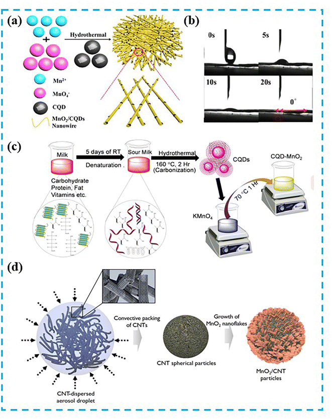 | ||
| Fig. 13 (a) Schematic diagram of the fabrication process of CQD-induced MnO2 nanowires composite films. (b) Images of CQD/MnO2 composite film and the shape of water droplets on the film at 0, 5, 10 and 20 s, respectively. Reproduced with permission from ref. 120. Copyright 2017, American Chemical Society. (c) Schematic representation of the synthesis of CQD and CQD/MnO2 nanohybrid materials. Reproduced with permission from ref. 121. Copyright 2018, Wiley-VCH. (d) Preparation diagram of CNT/MnO2 core–shell particles. Reproduced with permission from ref. 123. Copyright 2017, American Chemical Society. | ||
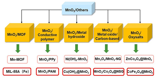 | ||
| Fig. 14 Recently reported heterogeneous junctions of MnO2-based electrode materials with other substances. | ||
Zhao et al.124 prepared MnO2/carbon nano-support sheet (CNS) arrays via Mn-MOF-derived CNS nanosheets (Fig. 15a). The pristine framework of Mn-MOF not only provided a path for fast electron transport and enhanced electrical conductivity. The in situ formed MnO2 nanosheet arrays and the derived carbon nanosheets also generated strong coupling, so the final electrode material achieved excellent capacitance and cyclic stability. Chen et al.125 via Fe2O3 derived from MIL-88A as a core and surface-modified it with an array of vertically grown MnO2 nanosheets. The as-synthesized Fe2O3@MnO2 material provided a sufficient interface for electrode–electrolyte contact due to the modification of nanosheet arrays. The large pore volume also provided portability for rapid ion diffusion, so it exhibited good capacitive performance (908.5 F g−1 at 1 A g−1) and cyclic stability. Fu et al.126 prepared core/sheath structured MnOx/PPy nanowires via in situ polymerization of polypyrrole (PPy) (Fig. 15b). Conductive VO was introduced into MnOx simultaneously during the formation of the PPy sheath. And the mesoporous PPy nanoparticles were used to form chemical bonds with their underlying layers to promote electron transfer and restraint the dissolution of Mn. Liu et al.127 obtained MnO2 nanosheet structures enriched with 3D mesopores interconnected with polyaniline (PANI) chains, which underwent a fast chemical oxidation polymerization reaction by electrostatically grafting the negatively charged surface of MnO2 with aniline monomers. Due to the exposure of the reaction center on the electrode surface and the porous structure formed by the combination of PANI chains, it could be used for electron transport and ion diffusion pathway shortening. Li et al.128 synthesized Ni(OH)2–MnO2 hierarchical nanosheet arrays. The formed heterostructure provided lattice fringe distortion as additional active centers, which combined the synergistic effect of the two to improve the capacitive performance (area capacitance of 14.7 F cm−2 at 2.5 mA cm−2) of the material. Wang et al.129 synthesized Cu(OH)2@MnO2 core–shell nanorod arrays on a copper foam substrate (Fig. 15c). The 1D Cu(OH)2 nanocrystalline nuclei provided a scaffold for MnO2 nanosheets growth and facilitated the ions and electrons to diffuse rapidly. The 2D MnO2 nanosheets used as the shell provided a great deal of active sites. Cui et al.130 reported novel Mn3O4/MnO2–NG hierarchical nanostructures (Fig. 15d). The 3D conductive network of NG provided an open path for electron/ion transport while being in close contact with Mn3O4/MnO2. The enhanced conductivity also increased the synergy of the components, which promoted the electrode reaction kinetics. Adaikalam et al.131 improved the problems of poor reversibility and stability in the presence of single MnO2 and Co3O4 electrodes by N and S double doped GO sheets. The overall mechanical strength and electrical conductivity of the material was also enhanced and allowed more ion penetration into the electrode. Hybridization of MnO2-based materials with oxygenates could enhance the electrochemical performance through their structural advantages. Gao et al.132 designed unique CoFe2O4@MnO2 nanoarrays based on nickel foam. The porous framework formed by CoFe2O4 contributed sites for the growth of MnO2, which promoted the enhancement of electronic/ionic conductivity. Jia et al.133 prepared ZnCo2O4@MnO2 core–shell structure in which the generation of MnO2 films could provide large specific surface areas to efficiently promote the rapid ion transport. The final result is reflected in the assembled ASC devices. Therefore, it shows different MnO2-based materials glowing LEDs for heterojunction engineering in Fig. 16.
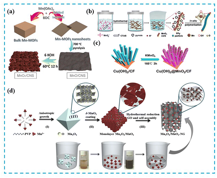 | ||
| Fig. 15 (a) Schematic diagram of the preparation of vertically aligned MnO2 nanosheets strongly coupled with carbon nanosheets. Reproduced with permission from ref. 124. Copyright 2018, Springer Nature. (b) Illustrative diagram of the formation of MnOx/PPy nanowires. Reproduced with permission from ref. 126. Copyright 2019, Elsevier Inc. (c) Schematic diagram of the synthesis of Cu(OH)2@MnO2/CF nanorod arrays. Reproduced with permission from ref. 129. Copyright 2019, Elsevier Inc. (d) Synthesis in process of Mn3O4/MnO2–NG and schematic representation of the specific nanostructures of Mn3O4 octahedral, as well as Mn3O4/MnO2 particles and Mn3O4/MnO2–NG. Reproduced with permission from ref. 130. Copyright 2018, Elsevier B.V. | ||
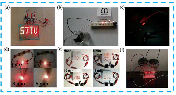 | ||
| Fig. 16 (a) Device of Ar-plasma treated α-MnO2 nanowires in two series powered 65 LEDs. Reproduced with permission from ref. 134. Copyright 2018, Elsevier B.V. (b) The V-shaped MnO2 powers four LEDs after charging. Reproduced with permission from ref. 116. Copyright 2021, Royal Society of Chemistry. (c) Digital image of a red LED lit by the ASC composed of MnO2/CNT. Reproduced with permission from ref. 123. Copyright 2017, American Chemical Society. (d) A red and a yellow LED illuminated by the single device of hierarchical MnO2–Mn3O4. Reproduced with permission from ref. 106. Copyright 2019, Elsevier Ltd. (e) Photographic images of two solid-state ASCs made of Cu(OH)2@MnO2/CF in series lighting a red LED bulb. Reproduced with permission from ref. 129. Copyright 2019, Elsevier Inc. (f) A digital image showing the two devices composed of CoFe2O4@MnO2 in series can lighten up ten red LED indicators. Reproduced with permission from ref. 132. Copyright 2017, Elsevier Ltd. | ||
The systematically summarizes the adjustment of the electrochemical properties of MnO2-based electrode materials by different engineering strategies, and shows the differences of each strategy in Table 2. Overall, the results obtained are still far from the theoretical requirements.
| Strategy | Active materials | Cycle stability | Specific capacitance | Electrolyte | Rate stability | Ref. |
|---|---|---|---|---|---|---|
| Morphology engineering | MnO2 nanospheres thin films | 72.3% (after 1000 cycles) | 206.2 F g−1 at 1.25 A g−1 | 1 M Na2SO4 | 75.8% (1.25 to 5 A g−1) | 71 |
| α-MnO2 nanorods | 87% (after 100 cycles) | 152 F g−1 at 2.5 mA | 1 M Na2SO4 | 75% (2.5 to 10 mA) | 72 | |
| α-MnO2 nanowires | 78% (after 2000 cycles) | 180 F g−1 at 1 A g−1 | 1 M Na2SO4 | 40% (1 to 8 A g−1) | 73 | |
| α-MnO2 hollow spheres and hollow urchins | 89% (after 350 cycles) | 167 F g−1 at 2.5 mA | 1 M Na2SO4 | 74.3% (2.5 to 10 mA) | 74 | |
| δ-MnO2/GP | 87.2% (after 30![[thin space (1/6-em)]](https://www.rsc.org/images/entities/char_2009.gif) 000 cycles) 000 cycles) |
446.6 F g−1 at 1 A g−1 | 1 M NaNO3 | 66.8% (1 to 10 A g−1) | 75 | |
| Defect engineering | Defective MnO2 | 89.4% (after 4000 cycles) | 202 F g−1 at 1 A g−1 | 1 M Na2SO4 | NA | 79 |
| MnO2–C | 83.9% (after 10![[thin space (1/6-em)]](https://www.rsc.org/images/entities/char_2009.gif) 000 cycles) 000 cycles) |
286.9 F g−1 at 1 A g−1 | 1 M Na2SO4 | 78.4% (1 to 20 A g−1) | 80 | |
| 2D birnessite δ-MnO2 | 84.7% (after 5000 cycles) | 382 F g−1 at 5 mV s−1 | 1 M KOH | 67.4% (1 to 8 A g−1) | 81 | |
| MnOx@rGO microspheres | 90% (after 10![[thin space (1/6-em)]](https://www.rsc.org/images/entities/char_2009.gif) 000 cycles) 000 cycles) |
405 F g−1 at 1 A g−1 | 6 M KOH | 76.5% (1 to 20 A g−1) | 82 | |
| δ-MnO2 nanosheets | 83% (after 1000 cycles) | 306 F g−1 at 0.2 A g−1 | 1 M Na2SO4 | NA | 87 | |
| Ni–MnO2 | 85% (after 10![[thin space (1/6-em)]](https://www.rsc.org/images/entities/char_2009.gif) 000 cycles) 000 cycles) |
379 F g−1 at 1 A g−1 | 1 M Na2SO4 | 74.1% (1 to 20 A g−1) | 89 | |
| Al doped δ-MnO2 | 84% (after 5000 cycles) | 450 mF cm−2 at 0.1 mA cm−2 | 1 M Li2SO4 | 77.8% (0.1 to 2 mA cm−2) | 90 | |
| GdMnO2/Ni(OH)2 nanorods | 108.3% (after 10![[thin space (1/6-em)]](https://www.rsc.org/images/entities/char_2009.gif) 000 cycles) 000 cycles) |
118.61 mA h g−1 at 1 A g−1 | 2 M KOH | 57.5% (1 to 10 A g−1) | 20 | |
| B doped MnO2 film | NA | 269 F g−1 at 50 mV s−1 | 0.5 M Na2SO4 | 58.7% (2 to 500 mV s−1) | 92 | |
| Heterojunction engineering | Au–MnO2 nanowires | 97% (after 1000 cycles) | 249 F g−1 at 1 mV s−1 | 1 M Na2SO4 | 65.9% (1 to 5 mV s−1) | 96 |
| Nano-porous MnO2–Cu architecture | 95% (after 4000 cycles) | 2.8 F cm−2 at 5 mA cm−2 | 1 M Na2SO4 | 35.7% (5 to 25 mA cm−2) | 97 | |
| Mn2O3@MnO2 core–shell nanofibers | 86.5% (after 5000 cycles) | 225 F g−1 at 0.2 A g−1 | 1 M Na2SO4 | 39.8% (0.1 to 10 A g−1) | 98 | |
| Hierarchical MnO2–Mn3O4 | 99.3% (after 5000 cycles) | 406.2 F g−1 at 1 A g−1 | 1 M Na2SO4 | 68.8% (1 to 20 A g−1) | 99 | |
| Nanoflakes MnO2/rGO | 99.4% (after 5000 cycles) | 482.4 F g−1 at 10 mV s−1 | 1 M Na2SO4 | NA | 100 | |
| 3D-graphene/MnO2 foam | 92.2% (after 2000 cycles) | 333.4 F g−1 at 0.2 A g−1 | 1 M Na2SO4 | NA | 111 | |
| CQD–MnO2 | 100% (after 1200 cycles) | 189 F g−1 at 0.14 A g−1 | 1 M Na2SO4 | 34.4% (0.14 to 2 A g−1) | 114 | |
| MnO2/CNS nanosheet arrays | 96.1% (after 5000 cycles) | 339 F g−1 at 0.5 A g−1 | 1 M Na2SO4 | 53.8% (0.5 to 2 A g−1) | 117 | |
| MnOx/PPy nanowires core/sheath structure | 97.4% (after 10![[thin space (1/6-em)]](https://www.rsc.org/images/entities/char_2009.gif) 000 cycles) 000 cycles) |
1091.4 F g−1 at 1 A g−1 | 1 M Na2SO4 | 81.6% (1 to 20 A g−1) | 119 | |
| Cu(OH)2@MnO2/CF core–shell nanorods array | 85.17% (after 5000 cycles) | 708.6 mF cm−2 at 2 mA cm−2 | 6 M KOH | 74.65% (2 to 20 mA cm−2) | 122 | |
| MnO2/Co3O4 with N and S co-doped GO | 95% (after 10![[thin space (1/6-em)]](https://www.rsc.org/images/entities/char_2009.gif) 000 cycles) 000 cycles) |
614 F g−1 at 1 A g−1 | 6 M KOH | 57% (1 to 30 A g−1) | 124 |
6. Summary and perspectives
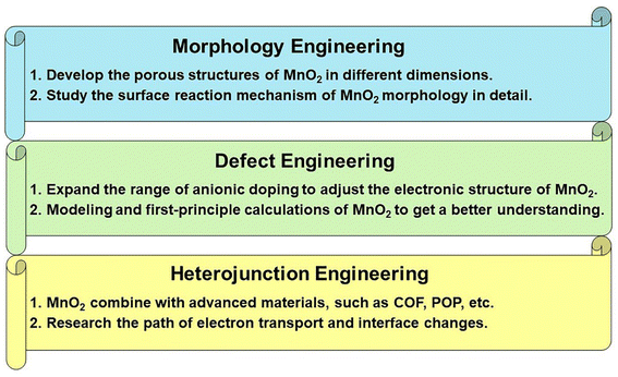
MnO2 is a potential electrode material in both crystal structure control and energy storage. In this review, we give a systematic description of various strategies based on MnO2-based electrode materials through morphology engineering, defect engineering and heterojunction engineering. Many strategies are used to prepare MnO2-based electrode materials to improve their electrochemical properties. However, there are still problems that deserve our attention, whether using strategies such as morphology engineering or defect engineering, which are only matter of fact, all lacking a systematic process and mechanism analysis of a single strategy. As a conclusion, MnO2-based electrode materials still have numerous difficulties to overcome, while leaving some space for more in-depth exploration (Fig. 17).The following are issues that may need to be solved immediately:
(1) The morphology engineering based on MnO2 nanostructures can be used to influence the final electrochemical performance by means of extrinsic modification. For example, increasing specific surface area and exposing effective active sites, shortening ion diffusion paths and electron transport distances, and promoting charge transfer and accelerating reaction kinetics.81–83 At present, a large number of synthetic methods on the morphology and porous structure of MnO2 have been developed to enhance its electrochemical behavior. Most studies are limited to the same dimension, and they lack systematic studies on the formation of MnO2 porous structure in multi-dimensional space. In the process of electrochemical reaction, the existence of disproportionation reaction will lead to the reduction of specific surface area or the reduction of effective active sites in the MnO2 structure. Moreover, the more complex structure of MnO2 also requires a complete set of theories to describe the surface reaction mechanisms corresponding to different morphologies. Therefore, this type of research is relatively lacking, and new methods need to be explored to obtain structures with excellent properties and certain stability. We should focus on the reports which related to new technologies and methods to stabilize the morphology and structure of MnO2. In addition, it is quite difficult to obtain high-purity crystalline MnO2, and it is urgent to develop new strategies to prepare single-phase MnO2 materials.
(2) Defect engineering can adjust the electronic structure of MnO2-based materials effectively according to the formation mechanisms of different defects. For instance, oxygen vacancy can change the bond length by adjusting the state of the active centers. And cation vacancies can provide additional intercalation sites to enhance the storage capacitance. Besides, cationic doping and anionic doping can use positive and negative charge attraction and different positions in the lattice to change the structure band gap, thereby enhancing conductivity and releasing electrochemical activity.88,89,93,98 There are few reports on anionic doping as MnO2-based electrode materials, so that the reaction mechanism of electrode materials in electrolyte is not perfect. Therefore, it is necessary to expand the research scope of anions to deeply understand and explore them in this regard.
(3) The construction of MnO2-based heterojunction materials is one of the most effective strategies to enhance the electrochemical performance. The electronic structure is regulated by the interaction generated by binding with other substances, promoting the charge transfer kinetics, building the porous structure and improving the stability of the structure.127–132 Up to now, great progress has been made and the exploration of heterojunctions is not over yet, so further efforts are still needed. In the future research process, it can focus on combining MnO2 with advanced materials (such as COF, POP, etc.) to form heterojunction materials. Based on the above basis, advanced characterization methods are used to deeply explore the changes of its electron transport paths and interfaces.
In summary, the reaction mechanisms of MnO2 as electrode materials for SCs need to be further explored and refined. We sincerely hope that the review will provide an overview of the study progress of MnO2-based electrode materials for SC and theoretical guidance for subsequent basic and applied research.
Author contributions
Juyin Liu: project conceptualization, methodology, investigation, writing – original draft, writing – review & editing, visualization. Jiali Bao: writing – review & editing. Xin Zhang: writing – review & editing. Yanfang Gao: resources, funding acquisition. Yao Zhang: supervision. Ling Liu: writing – review & editing, resources, funding acquisition. Zhenzhu Cao: writing – review & editing.Conflicts of interest
There are no conflicts to declare.Acknowledgements
This work was supported by the National Natural Science Foundation of China (No. 21566030) and Ministry of Science and Technology China-South Africa Joint Research Program (No. CS08-L15), Project of Inner Mongolia Education Department (NJZY089), Natural Science Foundation of Inner Mongolia (2015MS0205), Scientific Research Startup Foundation Project (No. DC2200000899), the National Natural Science Foundation of China (No. 22165021), Scientific Foundation of High Education Institutes Inner Mongolia of China (NJZY20071), and creative talents team of “Prairie Talent” engineering industry and the “Prairie Talent” of organization Department of Inner Mongolia Party Committee.References
- P. Simon and Y. Gogotsi, Nat. Mater., 2008, 7, 845–854 CrossRef CAS.
- G. Ma, M. Dong, K. Sun, E. Feng, H. Peng and Z. Lei, J. Mater. Chem. A, 2015, 3, 4035–4041 RSC.
- R. M. John and P. Simon, Science, 2008, 321, 651–652 CrossRef.
- R. Wang, M. Yao and Z. Niu, Smart supercapacitors from materials to devices, InfoMat, 2020, 2, 113–125 CrossRef CAS.
- Y. Su, N. Li, L. Wang, R. Lin, Y. Zheng, G. Rong and M. Sawan, Adv. Mater. Technol., 2022, 7, 2100608 CrossRef CAS.
- M. Shi, C. Yang, X. Song, L. Zhao, J. Liu, P. Zhang and L. Gao, Adv. Sustainable Syst., 2017, 1, 1700044 CrossRef.
- R. K. Sarojini, K. Palanisamy, P. Sanjeevikumar and J. B.-H. Nielsen, IET Renew. Power Gener., 2020, 14, 1156–1163 CrossRef.
- L. Chai, P. Wang, X. Liu, Y. Sun, X. Li and J. Pan, J. Power Sources, 2022, 532, 231324 CrossRef CAS.
- X. Gang, M. Krishnamoorthy, W. Jiang, J. Pan, Z. Pan and X. Liu, Carbon, 2021, 171, 62–71 CrossRef CAS.
- L. Sheng, L. Jiang, T. Wei, Z. Liu and Z. Fan, Adv. Energy Mater., 2017, 7, 1700668 CrossRef.
- H. Jin, X. Feng, J. Li, M. Li, Y. Xia, Y. Yuan, C. Yang, B. Dai, Z. Lin, J. Wang, J. Lu and S. Wang, Angew. Chem., Int. Ed., 2019, 58, 2397–2401 CrossRef CAS.
- H. S. Kim, J. B. Cook, H. Lin, J. S. Ko, S. H. Tolbert, V. Ozolins and B. Dunn, Nat. Mater., 2017, 16, 454–460 CrossRef CAS.
- S. Liu, A. Li, C. Yang, F. Ouyang, J. Zhou and X. Liu, Appl. Surf. Sci., 2022, 571, 151306 CrossRef CAS.
- A. Muzaffar, M. B. Ahamed, K. Deshmukh and J. Thirumalai, Renewable Sustainable Energy Rev., 2019, 101, 123–145 CrossRef CAS.
- Z. K. He, Y. Lu, C. Zhao, J. Zhao, Z. Gao and Y. Y. Song, Appl. Surf. Sci., 2021, 567, 150832 CrossRef CAS.
- M. Y. Chung and C. T. Lo, Electrochim. Acta, 2020, 364, 137324 CrossRef CAS.
- I. Ryu, D. Kim, G. Choe, S. Jin, D. Hong and S. Yim, J. Mater. Chem. A, 2021, 9, 26172–26180 RSC.
- K. C. Devarayapalli, K. Lee, H. B. Do, N. N. Dang, K. Yoo, J. Shim and S. V. P. Vattikuti, Mater. Today Energy, 2021, 21, 100699 CrossRef CAS.
- Z. Shi, L. Xing, Y. Liu, Y. Gao and J. Liu, Carbon, 2018, 129, 819–825 CrossRef CAS.
- M. B. Poudel and H. J. Kim, J. Energy Chem., 2022, 64, 475–484 CrossRef CAS.
- Z. Shi, J. Liu, Y. Gao and Y. Xu, J. Mater. Sci., 2021, 56, 1612–1629 CrossRef CAS.
- G. Manibalan, Y. Govindaraj, J. Yesuraj, P. Kuppusami, G. Murugadoss, R. Murugavel and M. R. Kumar, J. Colloid Interface Sci., 2021, 585, 505–518 CrossRef CAS.
- Y. Zhang, X. Yuan, W. Lu, Y. Yan, J. Zhu and T. W. Chou, Chem. Eng. J., 2019, 368, 525–532 CrossRef CAS.
- J. R. Choi, J. W. Lee, G. Yang, Y. J. Heo and S. J. Park, Catalysts, 2020, 10, 256 CrossRef CAS.
- Y. Mao, J. Xie, C. Guo, H. Liu, H. Xiao and W. Hu, Chem. Eng. J., 2021, 426, 131188 CrossRef CAS.
- Y. Wei, M. Zheng, W. Luo, B. Dai, J. Ren, M. Ma, T. Li and Y. Ma, All pseudocapacitive MXene-MnO2 flexible asymmetric supercapacitor, J. Energy Storage, 2022, 45, 103715 CrossRef.
- S. G. Mohamed, S. Y. Attia and H. H. Hassan, Microporous Mesoporous Mater., 2017, 251, 26–33 CrossRef CAS.
- N. R. Chodankar, D. P. Dubal, Y. Kwon and D.-H. Kim, NPG Asia Mater., 2017, 9, e419 CrossRef CAS.
- L. Lin, S. Tang, S. Zhao, X. Peng and N. Hu, Electrochim. Acta, 2017, 228, 175–182 CrossRef CAS.
- H. Wu, Z. Lou, H. Yang and G. Shen, Nanoscale, 2015, 7, 1921–1926 RSC.
- M. Isacfranklin, S. Daphine, R. Yuvakkumar, L. Kungumadevi, G. Ravi, A. G. Al-Sehemi and D. Velauthapillai, Ceram. Int., 2022, 48, 24745–24750 CrossRef CAS.
- Q. Ma, F. Cui, J. Zhang and T. Cui, J. Colloid Interface Sci., 2023, 629, 649–659 CrossRef CAS.
- A. K. Das, N. H. Kim, S. H. Lee, Y. Sohn and J. H. Lee, Composites, Part B, 2018, 150, 269–276 CrossRef CAS.
- A. K. Das, N. H. Kim, S. H. Lee, Y. Sohn and J. H. Lee, Composites, Part B, 2018, 150, 234–241 CrossRef CAS.
- P. Zhang and H. He, J. Alloys Compd., 2020, 826, 153993 CrossRef CAS.
- Y. Dong, Y. Wang, Y. Xu, C. Chen, Y. Wang, L. Jiao and H. Yuan, Electrochim. Acta, 2017, 225, 39–46 CrossRef CAS.
- X. Zheng, Y. Ye, Q. Yang, B. Geng and X. Zhang, Dalton Trans., 2016, 45, 572–578 RSC.
- S. Nagamuthu, S. Vijayakumar, S.-H. Lee and K.-S. Ryu, Appl. Surf. Sci., 2016, 390, 202–208 CrossRef CAS.
- Q. Zhao, A. Song, S. Ding, R. Qin, Y. Cui, S. Li and F. Pan, Preintercalation Strategy in Manganese Oxides for Electrochemical Energy Storage: Review and Prospects, Adv. Mater., 2020, 32, 2002450 CrossRef CAS.
- J. Shin, J. K. Seo, R. Yaylian, A. Huang and Y. S. Meng, Int. Mater. Rev., 2019, 1–32 Search PubMed.
- V. Veeramani, B. Dinesh, S. M. Chen and R. Saraswathi, J. Mater. Chem. A, 2016, 4, 3304–3315 RSC.
- S. B. Singh, T. I. Singh, N. H. Kim and J. H. Lee, J. Mater. Chem. A, 2019, 7, 10672–10683 RSC.
- S. Sun, G. Jiang, Y. Liu, B. Yu and U. Evariste, J. Energy Storage, 2018, 18, 256–258 CrossRef.
- A. Kumar, A. Thomas, A. Gupta, M. Garg, J. Singh, G. Perumal, E. Sujithkrishnan, P. Elumalai and H. S. Arora, J. Energy Storage, 2021, 42, 103100 CrossRef.
- K. Xiao, J. W. Li, G. F. Chen, Z. Q. Liu, N. Li and Y.-Z. Su, Electrochim. Acta, 2014, 149, 341–348 CrossRef CAS.
- Y. Wang, Y. Wang and L. Jiang, J. Appl. Electrochem., 2018, 48, 495–507 CrossRef CAS.
- M. J. Deng, P. J. Ho, C. Z. Song, S. A. Chen, J. F. Lee, J. M. Chen and K. T. Lu, Energy Environ. Sci., 2013, 6, 2178–2185 RSC.
- J. Cao, Y. Wang, Y. Zhou, J. H. Ouyang, D. Jia and L. Guo, J. Electroanal. Chem., 2013, 689, 201–206 CrossRef CAS.
- S. Sun, P. Wang, S. Wang, Q. Wu and S. Fang, Mater. Lett., 2015, 145, 141–144 CrossRef CAS.
- Z. Liu, J. Zhang, X. Yang, Y. He, Y. Bai, L. Kang, H. Xu, F. Shi and Z. Lei, J. Mater. Chem. A, 2016, 4, 9088–9096 RSC.
- C. Choi, H. J. Sim, G. M. Spinks, X. Lepró, R. H. Baughman and S. J. Kim, Adv. Energy Mater., 2016, 6, 1502119 CrossRef.
- T. Park, Y. Jang, J. W. Park, H. Kim and S. J. Kim, RSC Adv., 2020, 10, 14007–14012 RSC.
- M. Liu, L. Gan, W. Xiong, Z. Xu, D. Zhu and L. Chen, J. Mater. Chem. A, 2014, 2, 2555–2562 RSC.
- M. Li, J. Yu, X. Wang and Z. Yang, Appl. Surf. Sci., 2020, 530, 147230 CrossRef CAS.
- S. Devaraj and N. Munichandraiah, J. Phys. Chem. C, 2008, 112, 4406–4417 CrossRef CAS.
- S. D. Huang, C. Shang, X. J. Zhang and Z. P. Liu, Chem. Sci., 2017, 8, 6327–6337 RSC.
- W. Yao, G. M. Odegard, Z. Huang, Y. Yuan, H. Asayesh-Ardakani, S. Sharifi-Asl, M. Cheng, B. Song, R. Deivanayagam, F. Long, C. R. Friedrich, K. Amine, J. Lu and R. Shahbazian-Yassar, Nano Energy, 2018, 48, 301–311 CrossRef CAS.
- T. Barudžija, V. Kusigerski, N. Cvjetićanin, S. Šorgić, M. Perović and M. Mitrić, J. Alloys Compd., 2016, 665, 261–270 CrossRef.
- R. Yang, Y. Fan, R. Ye, Y. Tang, X. Cao, Z. Yin and Z. Zeng, Adv. Mater., 2021, 33, 2004862 CrossRef CAS.
- M. T. N. Dinh, C. C. Nguyen, T. L. T. Vu, V. T. Ho and Q. D. Truong, Appl. Catal., A, 2020, 595, 117473 CrossRef CAS.
- X. Wang and Y. Li, Chem. Commun., 2002, 764–765 RSC.
- Y. Chabre and J. Pannetier, Prog. Solid State Chem., 1995, 23, 1–130 CrossRef CAS.
- J. Zhao, Z. Tao, J. Liang and J. Chen, Cryst. Growth Des., 2008, 8, 2799–2805 CrossRef CAS.
- S. L. Brock, N. Duan, Z. R. Tian, O. Giraldo, H. Zhou and S. L. Suib, Chem. Mater., 1998, 10, 2619–2628 CrossRef CAS.
- C. H. Kim, Z. Akase, L. Zhang, A. H. Heuer, A. E. Newman and P. J. Hughes, J. Solid State Chem., 2006, 179, 753–774 CrossRef CAS.
- J. Greedan, N. Raju, A. Wills, C. Morin, S. Shaw and J. Reimers, Chem. Mater., 1998, 10, 3058–3067 CrossRef CAS.
- J. Wan, P. Ji, B. Li, Y. Xi, X. Gu, L. Huang, M. He and C. Hu, Chem. Commun., 2022, 58, 589–592 RSC.
- Q. Qu, P. Zhang, B. Wang, Y. Chen, S. Tian, Y. Wu and R. Holze, J. Phys. Chem. C, 2009, 113, 14020–14027 CrossRef CAS.
- H. Jiang, P. S. Lee and C. Li, Energy Environ. Sci., 2013, 6, 41–53 RSC.
- T. Brousse, D. Bélanger and J. W. Long, J. Electrochem. Soc., 2015, 162, A5185–A5189 CrossRef CAS.
- X. Liu, Y. Zheng and X. Wang, Chem.–Eur. J., 2015, 21, 10408–10415 CrossRef CAS PubMed.
- W. Huo, X. Liu and Y. Zhang, Nanoscale Adv., 2019, 2, 37–54 Search PubMed.
- Z. Sun, Y. Zhang, Y. Liu, J. Fu, S. Cheng, P. Cui and E. Xie, J. Power Sources, 2019, 436, 226795 CrossRef CAS.
- M. Huang, F. Li, F. Dong, Y. X. Zhang and L. L. Zhang, J. Mater. Chem. A, 2015, 3, 21380–21423 RSC.
- T. Brousse, M. Toupin, R. Dugas, L. Athouël, O. Crosnier and D. Bélanger, J. Electrochem. Soc., 2006, 153, A2171 CrossRef CAS.
- K. Chen, C. Sun and D. Xue, Phys. Chem. Chem. Phys., 2014, 17, 732–750 RSC.
- K. Naoi and P. Simon, Electrochem. Soc. Interface, 2008, 17, 34 CrossRef CAS.
- J. Shin, J. K. Seo, R. Yaylian, A. Huang and Y. S. Meng, Int. Mater. Rev., 2020, 65, 356–387 CrossRef CAS.
- B. S. Singu and K. R. Yoon, J. Alloys Compd., 2017, 695, 771–778 CrossRef CAS.
- N. Tang, X. Tian, C. Yang and Z. Pi, Mater. Res. Bull., 2009, 44, 2062–2067 CrossRef CAS.
- B. Yin, S. Zhang, Y. Jiao, Y. Liu, F. Qu and X. Wu, CrystEngComm, 2014, 16, 9999–10005 RSC.
- M. Xu, L. Kong, W. Zhou and H. Li, J. Phys. Chem. C, 2007, 111, 19141–19147 CrossRef CAS.
- W. Xie, J. Wang, X. Long, X. Wang, S. Zou, L. Zhang, H. Xu, Y. Fu, D. Liu, Y. Li, J. Li and D. He, J. Energy Storage, 2021, 35, 102308 CrossRef.
- L. Athouël, F. Moser, R. Dugas, O. Crosnier, D. Bélanger and T. Brousse, J. Phys. Chem. C, 2008, 112, 7270–7277 CrossRef.
- J. Zhu, W. Shi, N. Xiao, X. Rui, H. Tan, X. Lu, H. H. Hng, J. Ma and Q. Yan, ACS Appl. Mater. Interfaces, 2012, 4, 2769–2774 CrossRef CAS.
- R. E. John, A. Chandran, M. Thomas, J. Jose and K. C. George, Appl. Surf. Sci., 2016, 367, 43–51 CrossRef CAS.
- M. Khosravi, H. Feizi, R. Bagheri, Z. Song, B. Haghighi and M. M. Najafpour, New J. Chem., 2019, 43, 4049–4058 RSC.
- T. Xiong, Y. Zhang, W. S. V. Lee and J. Xue, Adv. Energy Mater., 2020, 10, 2001769 CrossRef CAS.
- Y. P. Zhu, C. Xia, Y. Lei, N. Singh, U. Schwingenschlögl and H. N. Alshareef, Nano Energy, 2019, 56, 357–364 CrossRef CAS.
- A. Zhang, R. Gao, L. Hu, X. Zang, R. Yang, S. Wang, S. Yao, Z. Yang, H. Hao and Y. M. Yan, Chem. Eng. J., 2021, 417, 129186 CrossRef CAS.
- R. Samal, M. Kandasamy, B. Chakraborty and C. S. Rout, Int. J. Hydrogen Energy, 2021, 46, 28028–28042 CrossRef CAS.
- F. Jing, Z. Ma, J. Wang, Y. Fan, X. Qin and G. Shao, Chem. Eng. J., 2022, 435, 135103 CrossRef CAS.
- D. Rolison and L. Nazar, MRS Bull., 2011, 36, 486–493 CrossRef CAS.
- H. Wang, J. Zhang, X. Hang, X. Zhang, J. Xie, B. Pan and Y. Xie, Angew. Chem., Int. Ed., 2014, 127, 1195–1199 Search PubMed.
- P. Gao, P. Metz, T. Hey, Y. Gong, D. Liu, D. D. Edwards, J. Y. Howe, R. Huang and S. T. Misture, Nat. Commun., 2017, 8, 14559 CrossRef CAS PubMed.
- L. T. Tseng, Y. Lu, H. M. Fan, Y. Wang, X. Luo, T. Liu, P. Munroe, S. Li and J. Yi, Sci. Rep., 2015, 5, 9094 CrossRef CAS PubMed.
- S. Yao, R. Zhao, S. Wang, Y. Zhou, R. Liu, L. Hu, A. Zhang, R. Yang, X. Liu, Z. Fu, D. Wang, Z. Yang and Y.-M. Yan, Chem. Eng. J., 2022, 429, 132521 CrossRef CAS.
- X. Zhang, X. Liu, Y. Zeng, Y. Tong and X. Lu, Small Methods, 2020, 4, 1900823 CrossRef CAS.
- H. Z. Chi, Y. Li, Y. Xin and H. Qin, Chem. Commun., 2014, 50, 13349–13352 RSC.
- S. Chen, Y. Xiang, W. Xu and C. Peng, Inorg. Chem. Front., 2019, 6, 199–208 RSC.
- W. Zhang, Y. Yang, R. Xia, Y. Li, J. Zhao, L. Lin, J. Cao, Q. Wang, Y. Liu and H. Guo, Carbon, 2020, 162, 114–123 CrossRef CAS.
- N. Zhang, C. Xu, H. Wang, J. Zhang, Y. Liu and Y. Fang, J. Mater. Sci.: Mater. Electron., 2021, 32, 1787–1799 CrossRef CAS.
- G. Luo, Int. J. Electrochem. Sci., 2020, 15, 515–525 CrossRef CAS.
- L. Khandare and S. Terdale, Appl. Surf. Sci., 2017, 418, 22–29 CrossRef CAS.
- W. Lu, Y. Li, M. Yang, X. Jiang, Y. Zhang and Y. Xing, ACS Appl. Energy Mater., 2020, 3, 8190–8197 CrossRef CAS.
- L. Kang, C. Huang, J. Zhang, M. Zhang, N. Zhang, Y. He, C. Luo, C. Wang, X. Zhou and X. Wu, Composites, Part B, 2019, 178, 107501 CrossRef CAS.
- M. Huang, Y. Zhang, F. Li, Z. Wang, Alamusi, N. Hu, Z. Wen and Q. Liu, Sci. Rep., 2014, 4, 4518 CrossRef.
- M. Huang, F. Li, X. L. Zhao, D. Luo, X. Q. You, Y. X. Zhang and G. Li, Electrochim. Acta, 2015, 152, 172–177 CrossRef CAS.
- R. Rajagopal and K.-S. Ryu, J. Electroanal. Chem., 2020, 856, 113669 CrossRef CAS.
- X. Y. Cao, X. Xing, N. Zhang, H. Gao, M. Y. Zhang, Y. C. Shang and X. T. Zhang, J. Mater. Chem. A, 2015, 3, 3785–3793 RSC.
- X. Zheng, Z. Han, W. Yang, F. Qu, B. Liu and X. Wu, Dalton Trans., 2016, 45, 16850–16858 RSC.
- H. Du, C. Wang and J. Lv, Solid State Commun., 2018, 277, 19–24 CrossRef CAS.
- P. M. Shafi, R. Dhanabal, A. Chithambararaj, S. Velmathi and A. C. Bose, ACS Sustainable Chem. Eng., 2017, 5, 4757–4770 CrossRef CAS.
- J. Zhu, D. Zhang, Z. Zhu, Q. Wu and J. Li, Ionics, 2021, 27, 3699–3714 CrossRef CAS.
- Z. J. Fan, J. Yan, F. Wei, G. Q. Ning, L. J. Zhi, J. C. Liu, D. X. Cao and G. L. Wang, ACS Nano, 2011, 5, 2787–2794 CrossRef CAS.
- S. Jangu, B. K. Satpathy, M. Raju, C. Jacob and D. Pradhan, Dalton Trans., 2021, 50, 6878–6888 RSC.
- H. W. Chang, Y. C. Huang, J. L. Chen, C. L. Chen, J. M. Chen, D. H. Wei, W. C. Chou, C. L. Dong and Y. C. Tsai, Catal. Today, 2022, 388, 63–69 CrossRef.
- X. L. Bai, Y. L. Gao, Z. Y. Gao, J. Y. Ma, X. L. Tong, H. B. Sun and J. A. Wang, Appl. Phys. Lett., 2020, 117, 183901 CrossRef CAS.
- J. Xu, K. Hou, Z. Ju, C. Ma, W. Wang, C. Wang, J. Cao and Z. Chen, J. Electrochem. Soc., 2017, 164, A430–A437 CrossRef CAS.
- H. Lv, X. Gao, Q. Xu, H. Liu, Y. G. Wang and Y. Xia, ACS Appl. Mater. Interfaces, 2017, 9, 40394–40403 CrossRef CAS.
- A. Prasath, M. Athika, E. Duraisamy, A. S. Sharma and P. Elumalai, ChemistrySelect, 2018, 3, 8713–8723 CrossRef CAS.
- W. S. Li, M. L. Chang, K. C. Chuang, Y. S. Li, J. D. Luo and H. C. Cheng, J. Electrochem. Soc., 2019, 166, A2194–A2198 CrossRef CAS.
- D. Gueon and J. H. Moon, ACS Sustainable Chem. Eng., 2017, 5, 2445–2453 CrossRef CAS.
- K. Zhao, Z. Xu, Z. He, G. Ye, Q. Gan, Z. Zhou and S. Liu, J. Mater. Sci., 2018, 53, 13111–13125 CrossRef CAS.
- Y. Chen, C. Kang, L. Ma, L. Fu, G. Li, Q. Hu and Q. Liu, Chem. Eng. J., 2021, 417, 129243 CrossRef CAS.
- J. Fu, Y. Zhang, H. Zhao, R. Jiang and R. Zhang, J. Colloid Interface Sci., 2020, 559, 39–44 CrossRef CAS PubMed.
- N. Liu, Y. Su, Z. Wang, Z. Wang, J. Xia, Y. Chen, Z. Zhao, Q. Li and F. Geng, ACS Nano, 2017, 11, 7879–7888 CrossRef CAS PubMed.
- J. Li, C. Wei, Y. Sun, Q. Liu, X. Zhang and J. Guo, Adv. Mater. Interfaces, 2019, 6, 1801470 Search PubMed.
- H. Wang, G. Yan, X. Cao, Y. Liu, Y. Zhong, L. Cui and J. Liu, J. Colloid Interface Sci., 2020, 563, 394–404 CrossRef CAS.
- M. Cui, S. Tang, Y. Ma, X. Shi, J. A. Syed and X. Meng, J. Power Sources, 2018, 396, 483–490 CrossRef CAS.
- K. Adaikalam, S. Ramesh, P. Santhoshkumar, H. S. Kim, H.-C. Park and H.-S. Kim, Int. J. Energy Res., 2022, 46, 4494–4505 CrossRef CAS.
- H. Gao, S. Cao and Y. Cao, Electrochim. Acta, 2017, 240, 31–42 CrossRef CAS.
- X. Jia, X. Wu and B. Liu, Dalton Trans., 2018, 47, 15506–15511 RSC.
- M. Jiang, C. Fu, J. Yang, Q. Liu, J. Zhang and B. Sun, Energy Storage Mater., 2019, 18, 34–42 CrossRef.
| This journal is © The Royal Society of Chemistry 2022 |

