 Open Access Article
Modular assembly of MOF-derived carbon nanofibers into macroarchitectures for water treatment†
Zishi
Zhang
a,
Chaohai
Wang
*a,
Yiyuan
Yao
a,
Hao
Zhang
a,
Jongbeom
Na
 bc,
Yujun
Zhou
a,
Zhigao
Zhu
 a,
Junwen
Qi
 a,
Miharu
Eguchi
bd,
Yusuke
Yamauchi
 *bd and
Jiansheng
Li
 *a
*a
aJiangsu Key Laboratory of Chemical Pollution Control and Resources Reuse, School of Environmental and Biological Engineering, Nanjing University of Science and Technology, Nanjing 210094, People's Republic of China. E-mail: wch2016@njust.edu.cn; lijsh@njust.edu.cn
bAustralian Institute for Bioengineering and Nanotechnology (AIBN) and School of Chemical Engineering, Faculty of Engineering, The University of Queensland, Brisbane, Queensland 4072, Australia. E-mail: y.yamauchi@uq.edu.au
cMaterials Architecturing Research Center, Korea Institute of Science and Technology, Seoul 02792, Republic of Korea
dJST-ERATO Yamauchi Materials Space-Tectonics Project and International Center for Materials Nanoarchitectonics (WPI-MANA), National Institute for Materials Science (NIMS), 1-1 Namiki, Tsukuba, Ibaraki 305-0044, Japan
First published on 25th July 2022
Abstract
The organized assembly of nanoparticles into complex macroarchitectures opens up a promising pathway to create functional materials. Here, we demonstrate a scalable strategy to fabricate macroarchitectures with high compressibility and elasticity from hollow particle-based carbon nanofibers. This strategy causes zeolitic imidazolate framework (ZIF-8)-polyacrylonitrile nanofibers to assemble into centimetre-sized aerogels (ZIF-8/NFAs) with expected shapes and tunable functions on a large scale. On further carbonization of ZIF-8/NFAs, ZIF-8 nanoparticles are transformed into a hollow structure to form the carbon nanofiber aerogels (CNFAs). The resulting CNFAs integrate the properties of zero-dimensional hollow structures, one-dimensional nanofibers, and three-dimensional carbon aerogels, and exhibit a low density of 7.32 mg cm−3, high mechanical strength (rapid recovery from 80% strain), outstanding adsorption capacity, and excellent photo-thermal conversion potential. These results provide a platform for the future development of macroarchitectured assemblies from nanometres to centimetres and facilitate the design of multifunctional materials.
The assembly of simple nanoparticles (such as silica, polystyrene and metal–organic frameworks) into macroarchitectures has a unique attraction for engineering materials due to their variable sizes, shapes, and chemical and physical properties.1–3 As a novel nanomaterial, the formed macroarchitecture with three-dimensional (3D) porous interconnected network structures has broad application prospects in various fields, including environment treatment, chemical sensing, energy storage, catalysis, and advanced electronic devices.4–7 Moreover, the functions of macroarchitectures are mainly determined by the fundamental building blocks. On account of large surface area, high porosity and more exposure to active sites, the complex macroarchitectures, which are assembled by building blocks with hollow structures, possess greater advantages.8,9
In the past few decades, in order to seek high-performance hollow building blocks for macroarchitectures, much effort has been put into it. In particular, the emergence of one-dimensional (1D) carbon hollow nanostructures, including hollow porous carbon nanofibers (HPCNs)10 and carbon nanotubes (CNTs)11 promotes the rapid development of this field. The HPCN- and CNT-based macroarchitectures realize the transformation from 1D nanomaterials to three-dimensional (3D) macroscopic materials with excellent properties (e.g., electrochemical energy storage and antimicrobial air filtration).12,13 Furthermore, these macroarchitectures can not only retain the characteristics of the 1D material, but also generate many new kinds of features (e.g., high specific surface area, high mechanical strength, and low density) that the components do not possess. Unfortunately, though the HPCN- and CNT-based macroarchitectures exhibit improved conductivity and stability properties, the synthesis of their building blocks is usually expensive and complex.14 Besides, the assembly of building blocks into 3D macroarchitectures usually exhibits relatively poor mechanical properties and requires some adhesives or templates, which have to be eliminated by extra strategies.15 These complex synthetic procedures and less favourable structural stability largely hinder the scale-up production of carbon aerogels and their practical applications.
To address these issues, we explore a novel and scalable method to synthesize functional macroarchitectures with robust mechanical properties fabricated from MOF-derived carbon nanofibers through manipulating nano-sized particles (MOFs) and micron-sized fibers. First, zeolitic imidazolate framework (ZIF-8) nanoparticles, which are spectacular for their large nitrogen content and surface area,16–18 are embedded into polyacrylonitrile (PAN)/polyvinylpyrrolidone (PVP) nanofibers to form ZIF-8-PAN/PVP composite nanofibers. Subsequently, the ZIF-8-PAN/PVP nanofibers are assembled into centimetre-sized nanofiber aerogels (ZIF-8/NFAs) by a freeze-drying technique. After preoxidation and carbonization of ZIF-8/NFAs, the carbon nanofiber aerogels with hollow and porous interlayer structures are fabricated (named C-ZIF-8-CNFAs). The interlayer structure of C-ZIF-8-CNFAs is very similar to natural luffa consisting of a network of elastic frameworks. As with the interconnected nanofibers in the interlayer structure, cellulose skeletons are in the interior of luffa interconnected in a highly uniform manner to maximize strength, a porous structure. Therefore, we refer to our porous structure as luffa-like. The prepared C-ZIF-8-CNFAs exhibit a low density of 7.32 mg cm−3, high specific surface area (288 m2 g−1), large hierarchical pore volume (0.22 cm−3 g−1), high mechanical strength (rapid recovery from 80% strain), outstanding adsorption capacity, and excellent photo-thermal conversion potential.
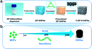
Fig. 1a depicts the assembly strategy of macroarchitectures (C-ZIF-8-CNFAs) schematically. The preparation process begins with the fabrication of ZIF-8/nanofibers (Fig. S1b†) using the method that ZIF-8 nanoparticles (Fig. S1a†) are incorporated into nanofibers by electrospinning (specific preparation methods in the ESI†). Upon homogenization in a mixed solution of ultrapure water and tert-butanol, the ZIF-8/nanofibers become wrapped around each other and dispersed uniformly. Subsequently, the homogenized nanofiber dispersion is frozen in a mold followed by freeze-drying into uncrosslinked ZIF-8/NFAs. To build further robust bonding among nanofibers, the obtained uncrosslinked ZIF-8/NFAs are preoxidized at 250 °C to form crosslinked ZIF-8/NFAs with a welding structure under the action of polyvinylpyrrolidone (PVP), providing elastic resilience to the resultant NFAs. Ultimately, the resulting preoxidized ZIF-8/NFAs are carbonized at 900 °C to form hollow C-ZIF-8-CNFAs under a N2 atmosphere. As a result of the carbonization, the organic ligands of ZIF-8 and molecules of PAN and PVP are decomposed and transformed into N-doped carbon materials. In addition, the Zn2+ in ZIF-8 nanoparticles is reduced to metallic Zn and then evaporated at high temperature.19–21 Nanoscale 0D MOFs are assembled into micron-scale 1D fibers, which are then assembled into centimeter-scale 3D carbon aerogels (Fig. 1b). This novel approach enables the super assembly on a multi-dimensional scale, which realizes the macroscopic application of nanoparticles and the functionalization of CAs. In order to verify that the performance of C-ZIF-8-CNFAs is improved after the introduction of ZIF-8, pure CNFAs (Fig. S2†) without ZIF-8 (the synthetic process is shown in the ESI†) are also prepared.
 | ||
| Fig. 1 Preparation steps for C-ZIF-8-CNFAs. (a) More fabrication details for C-ZIF-8-CNFAs. (b) Schematic illustration of the fabrication of CNFAs. | ||
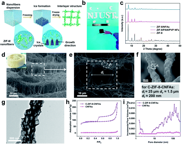
As illustrated in Fig. 2a, when the ZIF-8/nanofiber dispersion solution is frozen, the uniformly dispersed ZIF-8/nanofibers are extruded by the growth of ice crystals and assembled among ice crystals. After the sample is frozen completely, the nanofibers become lapped and locked into a 3D nanofibrous network. Subsequently, the ZIF-8/NFAs with a luffa-like structure are obtained after the sublimation of ice crystals through the freeze-drying process.22 Moreover, ZIF-8/NFAs can be made into diverse desired shapes such as cylinders, cubes, moon-like shapes, star-like shapes, heart-like shapes and intricate shapes of the letters (Fig. 2b). Fig. 2c shows the obvious reduction of the intensity of ZIF-8/NFA XRD patterns compared to the original ZIF-8, but the site hardly changes, which confirms that the introduced ZIF-8 nanoparticles are not destroyed during the electrospinning and the preparation process of aerogels. After the preoxidation and carbonization steps, the typical C-ZIF-8-CNFAs with an ultra-low density of 7.32 mg cm−3 can freely stand on the tip of a red maple leaf (Fig. 2b). The scanning electron microscopy (SEM) images in Fig. 2d–f show that C-ZIF-8-CNFAs have the hierarchical porous luffa-like structure with three kinds of pores (the picture of an actual luffa shown in the inset of Fig. 2d). The porous structure exhibits obvious rectangular pores of ∼25 μm, and the wall of these pores is made of interconnecting nanofibers (Fig. 2e). Meanwhile, the secondary pores of ∼1.5 μm are formed by the welded nanofibers that are interconnected with each other. The nanoscale pores of ∼200 nm also exist in these nanofibers, which come from the carbonization of ZIF-8 nanoparticles (Fig. 2f). As observed from the magnified SEM image (Fig. S3†), the welded structure resulting from preoxdiation is still preserved through carbonization. Remarkably, ZIF-8 nanoparticles encapsulated by PAN and PVP are transformed into a hollow structure after carbonization. As can be seen from the TEM image (Fig. 2g), the ZIF-8-derived hollow structure is evenly dispersed in PAN/PVP-derived carbon nanofibers. Because Zn2+ ions coordinate with –C![[triple bond, length as m-dash]](https://www.rsc.org/images/entities/char_e002.gif) N groups existing on the surface of PAN/PVP nanofibers, the ZIF-8 particles become tightly encapsulated by the PAN/PVP layers. During carbonization, the PAN/PVP layers make ZIF-8 shrink from inside to outside, thereby leading to the generation of a hollow structure. Moreover, the confined carbonization process within the PAN/PVP matrix prevents the irreversible fusion and aggregation of carbonized ZIF-8 nanoparticles.19
N groups existing on the surface of PAN/PVP nanofibers, the ZIF-8 particles become tightly encapsulated by the PAN/PVP layers. During carbonization, the PAN/PVP layers make ZIF-8 shrink from inside to outside, thereby leading to the generation of a hollow structure. Moreover, the confined carbonization process within the PAN/PVP matrix prevents the irreversible fusion and aggregation of carbonized ZIF-8 nanoparticles.19
After ZIF-8 nanoparticles were introduced into CNFAs, the properties have been improved significantly. To comprehend the variation of the porous characteristics in C-ZIF-8-CNFAs, nitrogen (N2) adsorption–desorption measurements were carried out. As observed from Fig. 2h and i, C-ZIF-8-CNFAs have a larger specific surface area of 288.3 m2 g−1 and pore volume of 0.22 cm−3 g−1, while the specific surface area and pore volume of CNFAs are only 12.1 m2 g−1 and 0.01 cm−3 g−1, respectively. Meanwhile, C-ZIF-8-CNFAs also have a hierarchical porous structure with micropores, mesopores, and macropores (Fig. 2i). Because of the existence of the hierarchical porous structure in C-ZIF-8-CNFAs, they have a lower density relative to CNFAs (20.73 mg cm−3) (Table S1†). The chemical compositions and graphitic structure of C-ZIF-8-CNFAs are investigated by X-ray powder diffraction (XRD) and X-ray photoelectron spectroscopy (XPS). The XRD pattern (Fig. S4a†) of C-ZIF-8-CNFAs only exhibits two broad peaks at about 25° and 44°, corresponding to the (002) and (101) diffraction facets of the graphitic structure, respectively.23 The correlative XPS spectrum shows that C-ZIF-8-CNFAs consist of C, N and O (Fig. S4b†). The high-resolution N 1s spectra (Fig. S4c†) can be deconvoluted into four peaks: pyridinic N (398.6 eV), pyrrolic N (399.4 eV), graphitic N (400.9 eV), and oxidized N (403.7 eV), respectively. The percentage of nitrogen and its types are listed in Table S2.† There is no Zn content thus indicating that it had evaporated during the carbonization process at high temperature (at 900 °C for 3 hours).24 Furthermore the N content of C-ZIF-8-CNFAs increases with the introduction of ZIF-8 compared to CNFAs clearly (Table S3†).
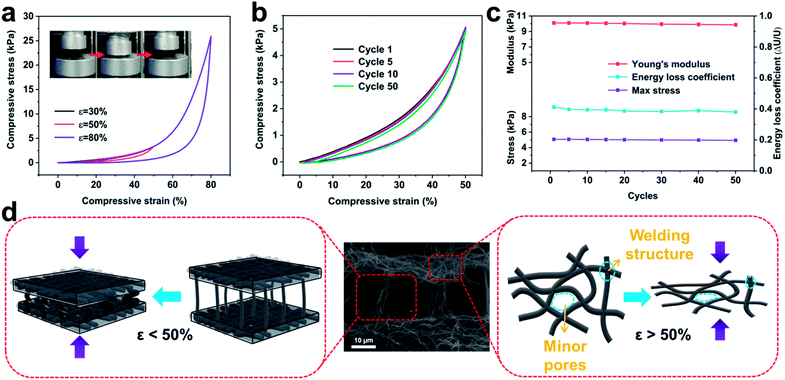
In stark contrast to the hard and brittle characteristics of conventional carbon aerogels, C-ZIF-8-CNFAs show robust mechanical properties, sustaining large compressive strain without fracture (insets in Fig. 3a and movie S1†). The compressive stress–strain (σ–ε) curves (Fig. 3a) show the compressive process of C-ZIF-8-CNFAs and two typical deformation regimes could be recognized: a Hookean or linear elastic regime of ε < 50% with a stable tangent modulus, and a densification regime of ε > 50% with σ and dσ/dε increasing sharply. When the maximum compressive strain increases from 30% to 80%, the maximum compressive stress steeply increases from 1.2 to 25.9 kPa, indicating that C-ZIF-8-CNFAs can bear over 25![[thin space (1/6-em)]](https://www.rsc.org/images/entities/char_2009.gif) 000 times their own weight without cracking. Moreover, the cyclic compression test of the C-ZIF-8-CNFAs is performed to validate their durable cycling performance by applying 50 loading–unloading fatigue cycles at a large ε of 50% (Fig. 3b). C-ZIF-8-CNFAs hardly undergo plastic deformation at all after the 50th cycle, which is a huge improvement over traditional CAs with a crisp character. As shown in Fig. 3c, C-ZIF-8-CNFAs retain nearly 100% of the initial value of the Young's modulus, maximum stress and energy loss coefficient, indicating that their strength or stiffness has no significant decline highlighting their exceptional structural robustness. Two reasons could account for the excellent mechanical elasticity of C-ZIF-8-CNFAs. On the one hand, the compressive strain is absorbed by the bending of the connected ZIF-8/nanofibers between layers; on the other hand, the strain that continues to grow (beyond 50%) is absorbed by the densification of minor pores, which is formed by the welding of PVP (Fig. 3d).25 The two reasons can also be confirmed by the sharp increase of the compressive stress after ε > 50% (Fig. 3a).
000 times their own weight without cracking. Moreover, the cyclic compression test of the C-ZIF-8-CNFAs is performed to validate their durable cycling performance by applying 50 loading–unloading fatigue cycles at a large ε of 50% (Fig. 3b). C-ZIF-8-CNFAs hardly undergo plastic deformation at all after the 50th cycle, which is a huge improvement over traditional CAs with a crisp character. As shown in Fig. 3c, C-ZIF-8-CNFAs retain nearly 100% of the initial value of the Young's modulus, maximum stress and energy loss coefficient, indicating that their strength or stiffness has no significant decline highlighting their exceptional structural robustness. Two reasons could account for the excellent mechanical elasticity of C-ZIF-8-CNFAs. On the one hand, the compressive strain is absorbed by the bending of the connected ZIF-8/nanofibers between layers; on the other hand, the strain that continues to grow (beyond 50%) is absorbed by the densification of minor pores, which is formed by the welding of PVP (Fig. 3d).25 The two reasons can also be confirmed by the sharp increase of the compressive stress after ε > 50% (Fig. 3a).
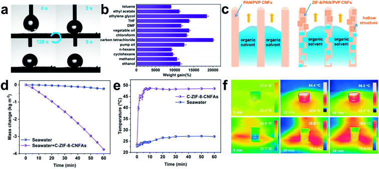
MOF-based derived CNFAs with hollow structures, ultra-low density, extraordinary mechanical elasticity, and large surface area are conducive to applications in various fields, including environment governance, energy absorption, and energy storage.26–28 As a proof of concept, we evaluated the organic solvent absorption and photo-thermal conversion performance of C-ZIF-8-CNFAs. Excellent hydrophobicity is one of the important factors to ensure the absorption efficiency of organic solvents. As demonstrated in Fig. 4a, C-ZIF-8-CNFAs exhibit high hydrophobicity with a water contact angle of 142° and the water contact angle has no significant change after 120 s. The water droplet and the absorbed oil droplet are on the surface of C-ZIF-8-CNFAs, indicating the effective oil/water selectivity of C-ZIF-8-CNFAs (Fig. S5†). As shown in Fig. 4b, C-ZIF-8-CNFAs demonstrate extraordinary absorption capacities for common oils and various organic solvents, 90–200 times their own weight, principally depending on the density and viscosity of the solvents. For example, the adsorption capacity for carbon tetrachloride (ρ = 1.595 g cm−3) is much higher than the adsorption capacity for n-hexane (ρ = 0.66 g cm−3). We also compared the maximum adsorption capacity of C-ZIF-8-CNFAs and CNFAs for several common organic solvents and oils. The adsorption performance of C-ZIF-8-CNFAs is also demonstrated to be better than that of CNFAs (Fig. S6†). According to the cross-sectional diagram of the adsorption of organic solvents (Fig. 4c), CNFAs only absorb organic solvents through the capillary phenomenon of the channel, which is formed by nanofibers, while the absorbed organic solvent can also enter into the hollow structure formed by carbonization of ZIF-8 inside the nanofiber of C-ZIF-8-CNFAs. Therefore, the performance of C-ZIF-8-CNFAs is significantly improved after the addition of ZIF-8 nanoparticles. Moreover, the adsorption capacity of C-ZIF-8-CNFAs for organic solvents is greater than that of previously reported aerogels (Fig. S7†). To verify the excellent adsorption performance of C-ZIF-8-CNFAs in practical application, the oil/water separation and cyclic adsorption experiments were carried out. As illustrated in Fig. S8,† C-ZIF-8-CNFAs can quickly absorb heavy organic solvents such as carbon tetrachloride (dyed with oil red) sunk at the bottom of water, thus indicating their potential application for selectively removing oils from water. Recyclability and reusability are also crucial to evaluate the practical application possibility of adsorption materials. In view of the outstanding elasticity and structural robustness of C-ZIF-8-CNFAs, we chose ethanol as the absorption solvent for recycling tests. Through simple heating, ethanol absorbed by C-ZIF-8-CNFAs can be readily removed. As demonstrated in Fig. S9a and b,† even after 10 cycles, C-ZIF-8-CNFAs still retained over 90% adsorption capacity for ethanol and their mass was reduced by less than 10%.
Given the abundant porous structure and blackbody characteristic, C-ZIF-8-CNFAs are also promising materials for interfacial solar steam generation (ISSG). To investigate the ISSG performance, the evaporation mass change of seawater and C-ZIF-8-CNFAs is measured under one sun illumination. As shown in Fig. 4d, the seawater in C-ZIF-8-CNFAs achieves the maximum evaporation rate of 3.74 kg m−2 h−1, which is 5.12 times the evaporation rate of bulk seawater (0.73 kg m−2 h−1) and 2.34 times faster than the evaporation rate of general 2D ISSG (∼1.6 kg m−2 h−1). An infrared camera is used to trace the surface temperatures of C-ZIF-8-CNFAs and bulk seawater under one-sun illumination to evaluate the photothermal behavior of ISSG (Fig. 4e). The surface temperature of C-ZIF-8-CNFAs presents a quick increase in 5 min and eventually reaches a stable state (∼48 °C) after 10 min, while the bulk seawater temperature stays unchanged (∼25 °C). The consecutive infrared images in Fig. 4f show the equilibrium temperature distribution and heat localization effect of C-ZIF-8-CNFAs and bulk seawater in 60 min under one-sun illumination.
Conclusions
In summary, we develop a facile method for the fabrication of CNFAs with a luffa-like structure by carbonization of ZIF-8/NFAs. Benefiting from the unique structure, C-ZIF-8-CNFAs demonstrate high specific surface area, large pore volume, and ultra-high mechanical strength. The modular assembly of C-ZIF-8-CNFAs shows great application prospects such as adsorption and photo-thermal conversion. Notably, this strategy can be extended to several MOFs (e.g., ZIF-67/NFAs, Fig. S10†). This work provides a new route to generate macroarchitectured assemblies from nanometres to centimetres.Author contributions
Z. Z. and C. W. synthesized the samples and wrote this manuscript. Z. Z. and C. W. equally contributed to this work. Y. Y., H. Z., J. N., and Y. Z characterized the materials. M. E., Z. Z., and J. Q revised the manuscript. J. L and Y. Y. conceived the experiments.Conflicts of interest
The authors declare no competing financial interest.Acknowledgements
This work was financially supported by the National Key Research and Development Program of China (No. 2019YFC0408302), National Natural Science Foundation of China (No. 51878352), the Natural Science Foundation of Jiangsu (BK20220969), and the JST-ERATO Yamauchi Materials Space-Tectonics Project (JPMJER2003). C. H. Wang acknowledges the support of the Initiative Postdocs Supporting Program (BX20200167). This work was performed in part at the Queensland node of the Australian National Fabrication Facility, a company established under the National Collaborative Research Infrastructure Strategy to provide nano and microfabrication facilities for Australia's researchers.Notes and references
- J. P. Randall, M. A. B. Meador and S. C. Jana, ACS Appl. Mater. Interfaces, 2011, 3, 613–626 CrossRef CAS PubMed.
- X. Wang and S. C. Jana, ACS Appl. Mater. Interfaces, 2013, 5, 6423–6429 CrossRef CAS PubMed.
- C. Avci, I. Imaz, A. Carne-Sanchez, J. A. Pariente, N. Tasios, J. Perez-Carvajal, M. I. Alonso, A. Blanco, M. Dijkstra, C. Lopez and D. Maspoch, Nat. Chem., 2018, 10, 78–84 CrossRef CAS PubMed.
- Z. Wu, H. Liang, B. Hu and S. Yu, Angew. Chem., Int. Ed., 2018, 57, 15646–15662 CrossRef CAS PubMed.
- H. Liang, Q. Guan, L. Chen, Z. Zhu, W. Zhang and S. Yu, Angew. Chem., Int. Ed., 2012, 51, 5101–5105 CrossRef CAS PubMed.
- F. Guo, Y. Jiang, Z. Xu, Y. Xiao, B. Fang, Y. Liu, W. Gao, P. Zhao, H. Wang and C. Gao, Nat. Commun., 2018, 9, 881 CrossRef PubMed.
- C. Wang, J. Kim, J. Tang, J. Na, Y. M. Kang, M. Kim, H. Lim, Y. Bando, J. Li and Y. Yamauchi, Angew. Chem., Int. Ed., 2020, 59, 2066–2070 CrossRef CAS PubMed.
- L. Chen, Y. Lu, L. Yu and X. Lou, Energy Environ. Sci., 2017, 10, 1777–1783 RSC.
- C. Zhao, X. Yin, Z. Guo, D. Zhao, G. Yang, A. Chen, L. Fan, Y. Zhang and N. Zhang, Chin. Chem. Lett., 2021, 32, 2254–2258 CrossRef CAS.
- W. Zhang, G. Cai, R. Wu, Z. He, H. Yao, H. Jiang and S. Yu, Small, 2021, 17, 2004140 CrossRef CAS PubMed.
- M. B. Bryning, D. E. Milkie, M. F. Islam, L. A. Hough, J. M. Kikkawa and A. G. Yodh, Adv. Mater., 2007, 19, 661–664 CrossRef CAS.
- Z. Lin, Z. Zeng, X. Gui, Z. Tang, M. Zou and A. Cao, Adv. Energy Mater., 2016, 6, 1600554 CrossRef.
- F. Wang, Y. Si, J. Yu and B. Ding, Adv. Funct. Mater., 2021, 31, 2107223 CrossRef CAS.
- J. Biener, M. Stadermann, M. Suss, M. A. Worsley, M. M. Biener, K. A. Rose and T. F. Baumann, Energy Environ. Sci., 2011, 4, 656–667 RSC.
- X. Zhang, Y. Zhang, Y. Qu, J. Wu, S. Zhang and J. Yang, Nano Lett., 2021, 21, 4167–4175 CrossRef CAS PubMed.
- C. Wang, J. Kim, J. Tang, M. Kim, H. Lim, V. Malgras, J. You, Q. Xu, J. Li and Y. Yamauchi, Chem, 2020, 6, 19–40 CAS.
- C. Wang, J. Kim, V. Malgras, J. Na, J. Lin, J. You, M. Zhang, J. Li and Y. Yamauchi, Small, 2019, 15, 190074 Search PubMed.
- X. Ren, X. Huang, Q. Wu, L. Tan, C. Fu, Y. Chen and X. Meng, Chin. Chem. Lett., 2021, 32, 3087–3089 CrossRef CAS.
- C. Wang, J. Kim, M. Kim, H. Lim, M. Zhang, J. You, J. Yun, Y. Bando, J. Li and Y. Yamauchi, J. Mater. Chem. A, 2019, 7, 13743–13750 RSC.
- Y. Pan, K. Sun, S. Liu, X. Cao, K. Wu, W. C. Cheong, Z. Chen, Y. Wang, Y. Li, Y. Liu, D. Wang, Q. Peng, C. Chen and Y. Li, J. Am. Chem. Soc., 2018, 140, 2610–2618 CrossRef CAS PubMed.
- P. Yin, T. Yao, Y. Wu, L. Zheng, Y. Lin, W. Liu, H. Ju, J. Zhu, X. Hong, Z. Deng, G. Zhou, S. Wei and Y. Li, Angew. Chem., Int. Ed., 2016, 55, 10800–10805 CrossRef CAS PubMed.
- G. Shao, D. A. H. Hanaor, X. Shen and A. Gurlo, Adv. Mater., 2020, 32, 1907176 CrossRef CAS PubMed.
- W. Xia, J. Tang, J. Li, S. Zhang, K. C. W. Wu, J. P. He and Y. Yamauchi, Angew. Chem., Int. Ed., 2019, 58, 13354–13359 CrossRef CAS PubMed.
- C. Liu, J. Wang, J. Li, J. Liu, C. Wang, X. Sun, J. Shen, W. Han and L. Wang, J. Mater. Chem. A, 2017, 5, 1211–1220 RSC.
- Y. Si, J. Yu, X. Tang, J. Ge and B. Ding, Nat. Commun., 2014, 5, 5802 CrossRef PubMed.
- T. Shang, Z. Lin, C. Qi, X. Liu, P. Li, Y. Tao, Z. Wu, D. Li, P. Simon and Q. Yang, Adv. Funct. Mater., 2019, 29, 1903960 CrossRef.
- H. Ou, P. Yang, L. Lin, M. Anpo and X. Wang, Angew. Chem., Int. Ed., 2017, 56, 10905–10910 CrossRef CAS PubMed.
- Z. Yu, G. Li, N. Fechler, N. Yang, Z. Ma, X. Wang, M. Antonietti and S. Yu, Angew. Chem., Int. Ed., 2016, 55, 14623–14627 CrossRef CAS PubMed.
Footnote |
| † Electronic supplementary information (ESI) available. See https://doi.org/10.1039/d2sc02619h |
| This journal is © The Royal Society of Chemistry 2022 |


