 Open Access Article
Tandem rigidification and π-extension as a key tool for the development of a narrow linewidth yellow hyperfluorescent OLED system†
Krzysztof
Bartkowski‡
 a,
Paola
Zimmermann Crocomo‡
 b,
Michał Andrzej
Kochman‡
c,
Dharmandra
Kumar
b,
Adam
Kubas
b,
Michał Andrzej
Kochman‡
c,
Dharmandra
Kumar
b,
Adam
Kubas
 *c,
Przemysław
Data
 *b and
Marcin
Lindner
 *a
*a
aInstitute of Organic Chemistry, Polish Academy of Sciences, Kasprzaka 44/52, Warsaw 01-224, Poland. E-mail: mlindner@icho.edu.pl
bFaculty of Chemistry, Silesian University of Technology, M. Strzody 9, Gliwice, 44-100, Poland. E-mail: przemyslaw.data@polsl.pl
cInstitute of Physical Chemistry, Polish Academy of Sciences, Kasprzaka 44/52, Warsaw 01-224, Poland. E-mail: akubas@ichf.edu.pl
First published on 21st July 2022
Abstract
Hyperfluorescence (HF), a relatively new phenomenon utilizing the transfer of excitons between two luminophores, requires careful pairwise tuning of molecular energy levels and is proposed to be the crucial step towards the development of new, highly effective OLED systems. To date, barely few HF yellow emitters with desired narrowband emission but moderate external quantum efficiency (EQE < 20%) have been reported. This is because a systematic strategy embracing both Förster resonance energy transfer (FRET) and triplet to singlet (TTS) transition as complementary mechanisms for effective exciton transfer has not yet been proposed. Herein, we present a rational approach, which allows, through subtle structural modification, a pair of compounds built from the same donor and acceptor subunits, but with varied communication between these ambipolar fragments, to be obtained. The TADF-active dopant is based on a naphthalimide scaffold linked to the nitrogen of a carbazole moiety, which through the introduction of an additional bond leads not only to π-cloud enlargement, but also rigidifies and inhibits the rotation of the donor. This structural change prevents TADF, and guides bandgaps and excited state energies to simultaneously pursue FRET and TTS processes. New OLED devices utilizing the presented emitters show excellent external quantum efficiency (up to 27%) and a narrow full width at half maximum (40 nm), which is a consequence of very good alignment of energy levels. The presented design principles prove that only a minor structural modification is needed to obtain commercially applicable dyes for HF OLED devices.
Introduction
Fundamental and applied studies of organic light-emitting diodes (OLEDs) have been encouraged by the rapid development of electronics such as smartphones, lighting, and flat panel displays.1 Fluorescent (1st generation) and phosphorescent (2nd generation) OLED emitters,2,3 which have been commercially available for 15 years, have suffered from insufficient colour purity, poor efficiencies, and lifetimes, as well as high manufacturing costs. Subsequently, a 3rd generation of metal-free, thermally activated delayed fluorescent (TADF)4–7 organic materials has been intensively explored within the last few years as promising candidates for commercial applications. The key feature of the operating mechanism of 3rd generation emitters is reverse intersystem crossing (rISC), in which the electron transfer proceeds from a triplet state to a singlet state. Light emission subsequently occurs by fluorescence from the singlet state. In most emitter compounds, the lowest singlet state is higher in energy than the lowest triplet state, meaning that rISC is a thermally activated process, and efficient rISC requires a small singlet-triplet energy gap (ΔEST). The minimization of ΔEST is therefore an important goal in the design and development of TADF materials.8 A minimized ΔEST results in emission of the total population of available photons. A general strategy to achieve low ΔEST values is to enforce a spatial separation between the HOMO and the LUMO.9,10 This design principle is implemented in donor–acceptor (D–A) molecular architectures where the electron-donating and electron-accepting moieties are partially decoupled from one another, for example, by a near-orthogonal orientation of the two moieties. Examples of this include cyanobenzene11 and dicyanopyrazine-based moieties,12 rigid heteroaromatic cores containing benzothiadiazole or oxazoles,13,14 dibenzo- and multiring- phenazines,15–21 heptazine,22 and aromatic imides.23–27 Despite tremendous progress made with this type of molecular engineering, a commonly encountered issue is a broad full-width at half-maximum (FWHM) ranging from 80 to 150 nm which is detrimental to colour purity.28,29 Furthermore, triplet–triplet or singlet–triplet annihilation adversely impacts the roll-off efficiency and lowers the operational lifetimes. A suitable approach to circumvent these problems could be the implementation of hyperfluorescence (HF) accelerated emission in OLED devices (4th generation of emitters).30 This approach, pioneered by Adachi,31 is based on the combination of a TADF assistant dopant (A, see Fig. 1) with a fluorescent emitter dopant (E, Fig. 1) in a host matrix.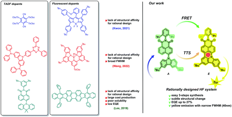 | ||
| Fig. 1 Current progress in the domain of green-to-yellow HF-OLED systems (left) and summary of the work presented herein (right). | ||
Because of the extraordinary electronic character (vide supra), the TADF-active molecule undergoes effective excitation. Then, from the singlet state of the assistant dopant (S1A), excitons are transferred to the lower-energy singlet state of the fluorescent dopant (SE1). This transfer, called FRET (Förster resonance energy transfer) plays a crucial role in the HF phenomenon. Excitons are pumped from the TADF dopant to the emissive species, which causes a spectacular increase in the emission efficiency. Benefits from FRET include not only higher quantum emission, but also the fine-tuning of the emission wavelength range. Both TADF and fluorescent dopants, however, must possess appropriate optical properties. Experimentally, this can be observed as a superposition of TADF-active and fluorescent emission and absorption wavelength ranges. Importantly, spectrally narrow emissions with efficient external quantum emissions (EQEs) have been identified mostly for blue and green HF emitters,30–35 while pursuing both parameters in yellow and more bathochromically shifted regions is troublesome as most of the ongoing work in this space provides systems that do not exceed 20% EQE34,36–41 or provide broad emission bands42 (Fig. 1). Therefore, a prerequisite of emission/absorption overlap seems to be insufficient.
Along this line, Brédas and co-workers43 showed theoretically that a double way of triplet harvesting is much more beneficial for the HF process when the S1 energy of the fluorescent dopant is only a slightly higher than the T energy of TADF dopants. This allows RISC mediated singlet to triplet exciton transfer, followed by FRET and direct triplet to singlet transfer (TTS) to occur parallelly, so as to potentially yield 100% of internal quantum efficiency (IQE).
Facing this challenge, herein, we propose unprecedented molecular design leading to strict control under the FMO energy gap and excited states energies to concomitantly fulfil both requirements. Our hyperfluorescent dye system is based on a tandem rigidification–π-extension modification of a naphthalimide (NI) motif (shown in Fig. 1, right) containing a twisted D–A–(D) electronic structure (2, 4) to an analogous, fully conjugated D–A architecture (6). Both flexible skeletons 2 and 4 exhibit TADF and high EQE when used as the emissive layer of OLED devices. The rigid but non-planar molecule 6 exhibits ordinary fluorescence with relatively poor EQE (up to 6%). A significant increase of emission efficiency is, however, noticed when compound 2 is doped with 6, which can be assigned to both FRET and TTS phenomena. The EQE of the resultant hyperfluorescent OLED device is increased to 27% with a FWHM of 40 nm. Effective energy transfer from TADF active 2 to fluorescent dye 6 proves the efficacy of the proposed modification strategy.
Results and discussion
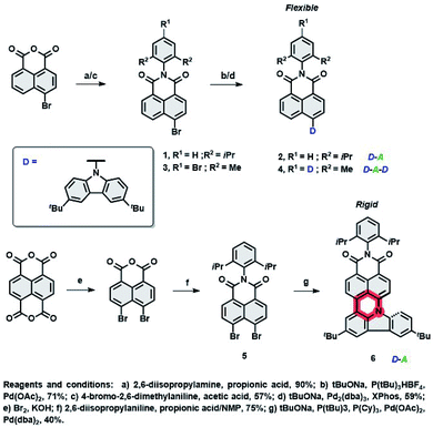
To realize hyperfluorescent emitters via the proposed molecular strategy (vide supra), we designed NI based architectures with donor–acceptor–(donor) electronic structures, which are envisaged to act as TADF (I) and fluorescent (II) dopants. Their design principles embrace (I) the utilization of a rigid scaffold with a limited number of rotating donors which could decrease ΔEST and HOMO–LUMO energy gaps, reducing the risk of nonradiative pathways from T1, as well as to suppressing unwanted Dexter energy transfer (DET); (II): increasing conjugation and the rigidity of the entire π-system by fusing the NI core with an electron rich group (through the formation of an additional six-membered ring, see Fig. 1), which would result in the formation of a nonplanar, molecular arrangement which simultaneously switches off the TADF property. This structural deviation provides a handle to govern excited state energies and the absorption region, prevent undesired aggregation, and elevate the efficiency of the photoluminescence quantum yield (PLQY). With these features in mind, the synthesis of compounds 2, 4 and 6 were performed within scalable 2–3 synthetic steps and are depicted in Scheme 1 (for the detailed procedures, see the ESI†). The intermediates 1 and 3 were first synthesized via condensation of commercially available 4-bromo-1,8-naphthalic anhydride with 2,6-diisopropyl- or 4-bromo-2,6-dimethyl-aniline, respectively. Subsequently, Buchwald–Hartwig cross-coupling reactions with 3,6-ditertbutylcarbazole (TbCbz) gave emitters 2 and 4 in 71 and 59% yield. For 6, an analogous synthetic pathway was employed to reach intermediate 5, which was then subjected to a one pot Buchwald–Hartwig cross-coupling/direct arylation reaction to provide the target molecule in an acceptable 40% yield.Crystallography
To evaluate the correlation between the molecular arrangements of compounds 2, 4, and 6 and their optical features, X-ray quality single crystals were obtained by slow evaporation from solutions of DCM, THF, and chloroform respectively. Compounds 2 and 4 crystallized in the monoclinic P21/c and orthorhombic Pbcn space groups, with four molecules per unit cell. A deeper insight into their molecular structures, displayed in Fig. 2, revealed a highly twisted conformation for both D–π–A, as well as the A–D–A triad, which is manifested by pronounced torsion angles (−113°, with respect to the plane determined by the naphthalene bridge) between TbCbz and the naphthalene backbone (exemplified for 2 in Fig. 2A). This entails a minimization of the undesired intermolecular π–π interaction as the closest C–H⋯π distances (shown in Fig. 2C and E) were 5.15 Å (2) and 7.39 Å (4). Dye 6 crystallizes in the triclinic![[P with combining macron]](https://www.rsc.org/images/entities/char_0050_0304.gif) 1 space group with a “head to tail” antiparallel alignment of two molecules in the primitive unit cell (Fig. 2D). Intriguingly, a striking difference in its solid-state behavior can be noticed as the twisting of the TbCBz group is inhibited (see Fig. 2B) through fusion with the NI core. The rationale for this modification was the rigidification of the entire skeleton and concurrent curvature introduced which is seen from the small torsion angles (−14.8° and 7.3°, Fig. 2B).
1 space group with a “head to tail” antiparallel alignment of two molecules in the primitive unit cell (Fig. 2D). Intriguingly, a striking difference in its solid-state behavior can be noticed as the twisting of the TbCBz group is inhibited (see Fig. 2B) through fusion with the NI core. The rationale for this modification was the rigidification of the entire skeleton and concurrent curvature introduced which is seen from the small torsion angles (−14.8° and 7.3°, Fig. 2B).
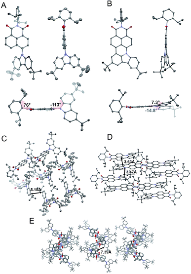 | ||
| Fig. 2 Crystallographic structures of 2 (A) and 6 (B). Space arrangement of 2 (C), 6 (D), and 4 (E). Thermal ellipsoids present 50% probability. Hydrogen atoms are omitted for the sake of clarity. | ||
Closer inspection of the packing mode of 6 (Fig. 2D) unveils an extended 2D structure in the crystal lattice maintained via two, very weak, C–H⋯π interactions with distances between 3.47 Å and 3.63 Å (Fig. 2D). This seems to be sufficient to avoid aggregation and guarantee spatial separation of FMOs as both structural parameters participate in the rational design of fluorescent structures.
Photophysics in solution and in the solid state
Initially, we investigated the UV-vis absorption and emissive properties of 2, 4, and 6. For the set of compounds, which differ from each other by the number of donors attached (2 is a D–A type emitter, whereas 4 D–A–D type emitter, respectively), UV-vis spectra (Fig. 3) in both nonpolar and polar solvents show transitions below 450 nm, similar to other D–A derivatives of NI.24 When it comes to compound 6, a red-shift of the absorption maxima by 80 nm is observed with respect to 2 and 4 which hold twisted substituents. This is consistent with the increased conjugation of this molecule. Consecutively, the charge transfer characteristics and impact of polarity on the photoluminescence quantum yield were evaluated (Fig. 3). For the set of D–A (2) and D–A–D (4) type of emitters, we observed distinct positive solvatochromism manifested by a strong, broad, emission band which shifts to lower energies with increased solvent polarity. Such optical behaviour is typical for emission from the charge transfer state (1CT). Accordingly, the PLQY also decreases with the increase in the polarity (Table 1). Conversely, for compound 6, in which the donor is fused with the acceptor and hence, the rotation around the C–N bond is minimized, the solvent polarity only has a minimal impact. The emission has a vibronic structure which is a hallmark of a localized excited state (1LE). | ||
| Fig. 3 Normalized absorption and emission spectra of compounds 2 (a), 4 (b), and 6 (c) in dichloromethane (DCM), tetrahydrofuran (THF) and toluene. | ||
| Compound | λ em, nma | Host | PLQY %b | τ PF, nsc | τ DF, μsd | DF/PFe | Eaf, eV | S 1, eVg | T 1, eVg | ΔEST, eVh |
|---|---|---|---|---|---|---|---|---|---|---|
| a Photoluminescence maximum. b Photoluminescence quantum yield. c Prompt fluorescence lifetime in the host. d Delayed emission lifetime in the host. e Delayed fluorescence (DF) to prompt fluorescence (PF) ratio in the host. f Activation energy of the triplet to singlet transfer. g Singlet and triplet energy in the host, based on the emission maxima. Error ± 0.03 eV. h Singlet-triplet energy splitting in Zeonex. Error ± 0.05 eV. | ||||||||||
| 2 | 509 | Zeonex | 61 | 17.97 | 1.59 | 0.21 | 0.012 | 2.43 | 2.12 | 0.31 |
| 536 | mCP | 87 | 14.21 | 20.43 | 2.49 | 0.075 | 2.31 | 2.08 | 0.24 | |
| 4 | 518 | Zeonex | 4 | 14.97 | 1.478 | 0.75 | 0.028 | 2.40 | 2.09 | 0.31 |
| 544 | mCP | 78 | 12.76 | 7.112 | 2.96 | 0.070 | 2.28 | 2.07 | 0.21 | |
| 6 | 564 | Zeonex | 84 | 8.78 | — | — | — | 2.20 | 2.20 | 0.00 |
| 567 | mCP | 95 | 9.21 | — | — | — | 2.19 | 2.19 | 0.00 | |
| 1% 6 and 10% of 2 | 567 | mCP | 97 | 53.50 | 8.81 | 8.79 | 0.029 | 2.19 | 2.09 | 0.10 |
Consequently, we switched further studies to the solid state, due to the fact that the main goal was to estimate the probability of using the follow-up analysis in a solid matrix. Thus, two matrices were selected: the non-polar aliphatic medium Zeonex and a small molecule mCP (1,3-bis(N-carbazolyl)benzene).
Based on the CV and HOMO–LUMO analysis (Fig. S11, ESI†), mCP was chosen for OLED device application (Fig. 4).
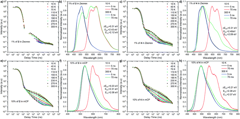 | ||
| Fig. 4 Time-resolved spectra and transient decays of thin films of compounds 2 and 4 in Zeonex and mCP at different temperatures. | ||
The most significant difference between these three emitters is that compounds 2 and 4 exhibit emission above microsecond delay time (Fig. 4) while 6 only has a nanosecond emission profile (Fig. 5). The lack of DF for 6 is clearly visible during the oxygen quenching experiment. While the spectrum of TADF active molecule 2 is rapidly changed upon exposure to oxygen, the spectrum of 6 stays intact (see Fig. S10, ESI†). The rationale for this is the lack of motion between the donor and acceptor moiety, which is related to rigidification (thus, charge transfer is not observed (see Fig. S11, ESI†), which is consistent with our previous observation in solution).
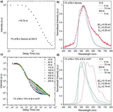 | ||
| Fig. 5 Photophysical characterisation of compound 6 in Zeonex (a and b) and in 10% of 2 in mCP (c and d). | ||
Nevertheless, closer inspection of the emission spectra around 300 K, above the microsecond delay time, suggests diverse emissive behaviour with respect to the host used. Dye 2 initially, above 2.5 μs, exhibits delayed emission similar to prompt fluorescence, recognized as the TADF process. However, a tail, whose intensity is enhanced significantly with further delay, is found by an RTP process. An analogous, but less pronounced effect was determined for compound 4 in the Zeonex matrix. However, both emitters in the mCP matrix showed different responses. Namely, the delayed emission coming through the TADF process starts to intensify above 300 ns (at 300 K) and is visible above 70 ms. A plausible explanation for this different behaviour needs a deeper insight into fluorescence emission showing a vibronic structure in the Zeonex matrix. This suggests the emission stemming from the 1LE state (Fig. 4b, d and 5b) whereas in the mCP host the emission bears a 1CT characteristic (Fig. 4f and h). Among all emitters, phosphorescence occurred from the localized excited state (3LE). The dual delayed emission in the Zeonex matrix, which appears rarely, is not unprecedented in photophysical studies,44,45 and could be elucidated based on the El-Sayed rule, in which the rate of (reverse) intersystem crossing is very high if the radiation-less transition involves changing the type of the orbital. Transfer of the excited state between the 3LE and 1CT is such an example, but in the Zeonex matrix, the transfer is between the 3LE and 1LE or mixed 1CT and1LE. In this case, and due to the higher ΔEST gap, there is a higher chance of observing the RTP process rather than TADF.
As for the behaviour of the emitters in the mCP matrix, strong TADF emission was noticed. This is strongly pronounced taking into account the high DF/PF parameter (close to 3) which suggests almost 100% internal efficiency of the triplet harvesting process (Table 1). On top of that, a very high PLQY in the mCP matrix, 87% for 2 and 78% for 4, gives a promising perspective for TADF based OLED emitters. Using eqn (1), it is possible to estimate the theoretical maximum OLED external quantum efficiency (EQE), which in our case could be up to 26.1% for OLEDs based on compound 2 and 23.4% for those based on compound 4.
| EQE = ηoutηflγηfr | (1) |
The highest PLQY efficiency in mCP was obtained for compound 6; nevertheless, due to the fact that we only observed fluorescence emission in this compound, the parameter concerning the amount of the excited state is ηfr = 0.25. This suggests that the typical OLED structure will have an efficiency of up to 7% which is substantially smaller than for TADF based emitters. On the other hand, one can notice that because emitter 6 has no CT broad emission it is not affected by the matrix, and the emission of compound 2 and partial emission of compound 4 overlap the absorption spectra of compound 6 (Fig. 3, 4 and 5). The latter factor paves the way towards the desired FRET process between TADF compound 2 and fluorescence emitter 6. Fluorescence emission of the mixture of the compounds 2 and 6 in mCP has a similar structure to single emitter 6 in mCP and additional delayed emission was observed at 300 K (Fig. 5c and d). The latter result is proof of the FRET process and is in addition to the obtained emissive hyperfluorescence structure. However, considering excited state energies for 2 and 6 given in Table 1, FRET is not only a driving force of the hyperfluorescence process. One can notice that a small energy difference between the S–T state favours effective rISC transition, subsequently forcing a singlet-to-singlet transition. At the same time, when the singlet energy of 6 lies solely 0.08 eV above the triplet energy of 2 (given in Table 1), TTS transition can occur according to the path shown in Fig. 6 truly profiting from the overall population of available triplets.
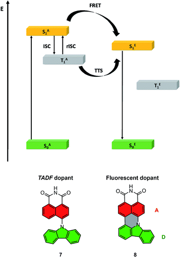 | ||
| Fig. 6 Energy diagram for the HF system, with the path towards double harvesting of the triplet via FRET and TTS (above); molecular structures of truncated model compounds 7 and 8 (below). | ||
Computational methods
To aid in the interpretation of the spectroscopic data for compounds 2, 4 and 6, we complemented their photophysics with electronic structure calculations. At the preliminary stage, we employed time-dependent density functional theory (TDDFT) in combination with the ωB97XD exchange-correlation functional.46 The results of these exploratory calculations are summarized in the ESI.†For the sake of convenience, the compounds under study were represented by truncated model molecules in which the 2,6-dialkylphenyl ring was removed, and the dangling bond was saturated with a hydrogen atom. The two tert-butyl groups on the TbCbz moiety were likewise removed and replaced with hydrogen atoms. Thus, compounds 2 and 4 were jointly represented by model compound 7, while compound 6 was represented by model compound 8 (see Fig. 6 for truncated structures). Owing to the relatively smaller sizes of compounds 7 and 8, we were able to treat their excited electronic states with a spin-opposite-scaled algebraic-diagrammatic construction method of second order (SOS-ADC(2)).47–52 The SOS-ADC(2) method has previously been found to give accurate predictions for the energies of intra- and intermolecular charge transfer states of various organic donor–acceptor compounds and molecular clusters,53–56 and we expect it to be reliable for the calculation of the optical properties of compounds 7 and 8.
We begin the discussion of the simulation results by examining the vertical excitation spectra of model compounds 7 and 8, which are given in Table 2. Accompanying this data, Fig. S9 (ESI†) shows ground-state equilibrium geometries of both compounds, and EDDMs for their respective lowest singlet and triplet excited states.
| Compound | State | ΔE, eV | f | μ, D |
|---|---|---|---|---|
| 7 (model of 2 and 4) | S0 | 2.4 | ||
| S1 (D → A ICT) | 3.767 | 0.132 | 15.7 | |
| S2 (A ππ*) | 4.055 | 0.013 | 3.0 | |
| S3 (D ππ*) | 4.156 | 0.064 | 1.5 | |
| S4 (A ππ*) | 4.408 | 0.223 | 6.4 | |
| T1 (A ππ*) | 2.890 | 0 | 3.1 | |
| T2 (D ππ*) | 3.671 | 0 | 2.6 | |
| T3 (D → A ICT) | 3.761 | 0 | 10.1 | |
| T4 (D ππ*) | 3.914 | 0 | 2.1 | |
| 8 (model of 6) | S0 | 5.3 | ||
| S1 (D + A ππ*) | 3.124 | 0.605 | 8.3 | |
| S2 (D + A ππ*) | 3.755 | 0.004 | 6.5 | |
| S3 (D + A ππ*) | 4.029 | 0.085 | 6.7 | |
| S4 (D + A ππ*) | 4.218 | 0.001 | 7.3 | |
| T1 (A ππ*) | 2.445 | 0 | 5.4 | |
| T2 (D + A ππ*) | 3.332 | 0 | 6.5 | |
| T3 (D ππ*) | 3.557 | 0 | 6.6 | |
| T4 (D + A ππ*) | 3.860 | 0 | 5.7 |
In compound 7, where the D moiety is twisted with respect to the A moiety, the lowest singlet excited state (S1) arises from intramolecular D → A charge transfer (ICT). Among the higher excited states, the S2 and S4 states are ππ*-type states that are localized on the D moiety, while the S3 state is a ππ*-type state localized within the A moiety. The S1 state has a higher oscillator strength (0.132) than either the S2 or the S3 states, which indicates that the first photoabsorption band of compound 7 arises predominantly from the S0 → S1 transition. This conclusion can be safely extrapolated to compounds 2 and 4.
The lowest triplet state of compound 7 (T1) is localized on the A moiety. It is essentially a counterpart of the T1 (3B2u) state of unsubstituted naphthalene, which is dominated by a HOMO → LUMO excitation.
Moving to compound 8, the additional linkage between the electron-donating and -accepting moieties has a strong effect on the electronic structures of the low-lying singlet states. In compound 8, the S1 state is a ππ*-type state that is delocalized over both the D and the A moieties, and it does not show a substantial ICT character. States S2 to S4 are likewise nonpolar. The S1 state has a high oscillator strength, and it is well separated in energy from the higher singlet excited states. It follows that the first photoabsorption band of compound 8 arises mainly from the intense S0 → S1 transition. By extrapolation, the same applies to compound 6.
The T1 state, on the other hand, remains largely localized on the A moiety, and it is similar to the T1 (3B2u) state of naphthalene.
To gain more insight into the photoluminescence properties of the systems under study, we optimized minima on the potential energy surfaces (PESs) of the S1 and T1 states of compounds 7 and 8. Fig. 6 shows the general idea of the HF system energy levels with marked FRET and rISC of the TADF dopant, while Fig. S6† presents the detailed results of the described analysis. We found that the selected model compounds meet the necessary conditions for acting as a FRET energy donor and acceptor pair. Namely, the calculated vertical S1 → S0 fluorescence emission energy of compound 7, at 3.159 eV, coincides closely with the calculated vertical S0 → S1 absorption energy of compound 8, which is 3.124 eV. This observation indicates that FRET can indeed occur from the photoexcited compound 7 onto compound 8. Furthermore, the minimum on the S1 state of compound 8 is located considerably lower in energy (more specifically, by 0.876 eV) than the vertical energy of the S1 state of compound 7 at its ground-state equilibrium geometry. This means that FRET from compound 7 onto compound 8 is effectively a one-way process; the electronic excitation cannot be transferred back onto compound 7.
Extrapolating to compounds 2, 4, and 6, we expect that unidirectional FRET likewise takes place from photoexcited compounds 2 and 4 onto compound 6.
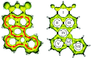
Lastly, Fig. 7 shows the ACID plots of molecule 8. To elucidate how strong the communication between the donor and acceptor moieties is, we distinguished the global ring current (with contribution of both σ and π MOs; Fig. 8, left) and π MO part (Fig. 8, right). Such a representation allowed us to present the competition between global and local delocalization within model molecule 8. Both TbCbz and naphthalene subunits are involved in the global diatropic current pathway as well as each remaining an individual aromatic system. Thus, even the local diatropic ring currents along NI and TbCbz are present, and the global aromaticity is a dominant phenomenon, in accordance with the observed spectroscopic properties. For only the π MO ACID plot, communication is significantly weaker. The donor (rings V, VI and VII) is only weakly coupled to the acceptor moiety (rings I, II, and III). Inspection of the directions of the ring currents indicates that within both naphthalene and TbCbz moieties a diatropic current is present, while the flow path of current along ring IV, which is located in between the donor and the acceptor subunits is slightly paratropic. Nevertheless, skeleton 8 is fully conjugated, even though the communication involves σ and π MOs. Analysis of the experimentally observed 1H NMR spectra of 2 and 6 (see the ESI†) showed down-field shifted signals of the TbCbz moiety (up to 1 ppm) confirming the enhancement of diatropic current within the whole conjugated skeleton including the donor subunit. This observation, aided by the computational analysis of skeletons 7 and 8, per analogiam, to structures 2 and 6 confirms that the presented strategy of π-delocalization extension and rigidification can be a useful tool for designing of HF active compounds.
OLED devices
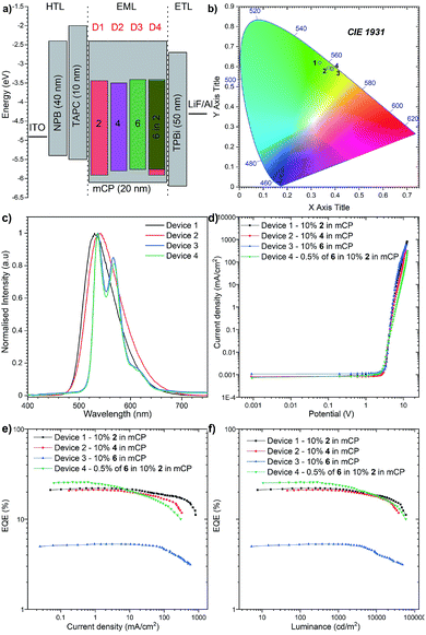
To investigate the applicability of the synthesized emitters, OLED devices were fabricated and characterized. The compounds were purified by sublimation before use. The investigated compounds were used as dopants in a mCP matrix which was suitable based on the obtained HOMO, LUMO, singlet and triplet energies. The OLED structures were deposited using high-vacuum thermal evaporators. Devices 1–3: ITO/NPB (40 nm)/TAPC (10 nm)/10% 2, 4, and 6 in mCP (20 nm)/TPBi (50 nm)/LiF (1 nm)/Al (100 nm) and Device 4: ITO/NPB (40 nm)/TAPC (10 nm)/0.5% 6, 10% 2 in mCP (20 nm)/TPBi (50 nm)/LiF (1 nm)/Al (100 nm) as is illustrated in Fig. 8a.The electroluminescence spectra of the measured devices correspond to the green-yellow region and match well with the photoluminescence spectra obtained from the initial photophysical analysis (Fig. 8b). The electrical turn-on voltage is low and similar for all devices at around 2.7 V. In terms of the “classical” efficiency, the highest was for device 1 based on compound 2, up to 22.1%. Devices 2 and 3 had up to 21.1% and 5.3% efficiencies respectively (Fig. 8c). These values are a slightly lower than the maximum theoretical values discussed above; nevertheless, the outcoupling factor varies between 20 and 30%, which suggests that in our case we had 100% of the IQE (internal quantum efficiency). An intriguing result was obtained for the hyperfluorescence structure, where the OLED EQE was 27% (Fig. 8e) exceeding those of all “classical” TADF devices.
The highest luminance was measured for Device 1 with compound 2 with a value close to 59![[thin space (1/6-em)]](https://www.rsc.org/images/entities/char_2009.gif) 000 cd m−2 (Fig. 8d). Nevertheless, the luminance behaviour was also very promising, and in all the devices, the value exceeds 30
000 cd m−2 (Fig. 8d). Nevertheless, the luminance behaviour was also very promising, and in all the devices, the value exceeds 30![[thin space (1/6-em)]](https://www.rsc.org/images/entities/char_2009.gif) 000 cd m−2, which together with high efficiency qualifies it for commercial OLED applications. Furthermore, compared with recently reported yellow HF-OLED devices (Fig. 9), the presented emitter system is one of the most promising ones to date.
000 cd m−2, which together with high efficiency qualifies it for commercial OLED applications. Furthermore, compared with recently reported yellow HF-OLED devices (Fig. 9), the presented emitter system is one of the most promising ones to date.
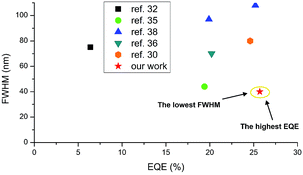 | ||
| Fig. 9 Summarized results of yellow HF-OLEDs reported to date. For ref. 30, 32 and 36 FWHM values were estimated based on the reported EL spectra. | ||
Conclusions
In conclusion, a new rational strategy for hyperfluorescent dye systems was proposed. Rigidification of a TADF active dopant with simultaneous extension of π electron conjugation by the introduction of only one new C–C bond allowed us to obtain a pair of two highly effective emitters.Photophysical properties of the investigated compounds were consistent with our presumption and both TADF active molecules showed a similar optical response. Thus, separation of an additional TbCbz donor group by using a benzene ring suppresses the communication between it and the acceptor. Because of this, dopant 2 was chosen as the first component for the hyperfluorescent system.
Computational analysis of the designed molecules revealed that for both dyes 2 and 4, the effective intramolecular charge transfer from donor to acceptor moieties is dominating, while for molecule 6 the main contribution of theππ* transition is observed. Furthermore, ACID plot analysis was performed and the effective global conjugation within the whole skeleton of 6 was confirmed, followed by 1H NMR spectral analysis that was consistent with the theoretical calculations. Thus, rationally designed rigidification of a twisted donor–acceptor scaffold can be used as a way of obtaining a globally delocalized skeleton with a bathochromically shifted absorption/emission maximum. This can indeed afford fine tuning of excited state energies to realize simultaneously realized FRET and TTS transitions.
OLED devices utilizing dyes 2, 4, and 6 were prepared and characterized. Acceptable EQEs for OLEDs based on 2 and 4 were recorded due to their TADF activities. Fluorescent dopant 6 showed classical behaviour as the emissive layer. A hyperfluorescent device obtained by doping the emissive layer with 2 and 6, however, showed an excellent EQE (27%) and FWHM (40 nm), in accordance with that expected for a HF OLED system. Additionally, to the best of our knowledge, this represents the first yellow HF OLED device, which exhibits such impressive performance.
The presented findings shed light on the potential of our proposed strategy for the design of new fluorescent dopant structures which is relevant for the future successful development of the 4th generation of OLED materials. Slight structural modification, allowing rigidification with simultaneous enhancement of π delocalization of the whole skeleton has led us to establish a simple method for the creation of an efficient HF system of emitters.
Data availability
The calculated equilibrium geometries of the compounds under study were deposited at https://repod.icm.edu.pl/dataset.xhtml?persistentId=doi:10.18150/NZ5GF.Author contributions
M. L. conceived and supervised the project; K. B. and M. L. designed, synthesized, and characterized all emitters; P. Z. C. and K. D. carried out basic photophysical and time-resolved spectroscopic studies, and fabricated and analysed the OLED devices, while P. D. analysed and interpreted the spectroscopic results; M. A. K and A. K. performed the computational studies; M. L. conceptualized the manuscript. K. B., M. A. K. A. K., P. D. and M. L. contributed to writing the manuscript.Conflicts of interest
There are no conflicts to declare.Acknowledgements
K. B. and M. L. acknowledge support from the National Centre for Research and Development, Poland, Grant No. LIDER/21/0077/L-11/19/NCBR/2020. M. L. is a recipient of a scholarship awarded by the Polish Ministry of Education and Science to outstanding young scientists. M. A. K. acknowledges funding from the European Union's Horizon 2020 research and innovation program under Marie Skłodowska-Curie grant agreement No. 847413. A. K. acknowledges support from the National Science Centre, Poland, Grant No. 2020/39/B/ST4/01952. This work has been published as part of an international co-financed project funded by the program of the Minister of Science and Higher Education entitled ``PMW′′ in the years 2020–2024; agreement no. 5005/H2020-MSCA-COFUND/2019/2. The simulations reported in this article were carried out with the use of the computational resources kindly provided to us by the Wrocław Centre for Networking and Supercomputing (WCSS, http://wcss.pl), the Centre of Informatics of the Tricity Academic Supercomputer and Network (CI TASK, https://task.gda.pl), and the Poznań Supercomputing and Networking Center affiliated to the Institute of Bioorganic Chemistry of the Polish Academy of Sciences (PCSS, https://www.pcss.pl). We gratefully acknowledge the generous support from these agencies. P. D. and P. Z. C. acknowledge funding from the Polish National Science Centre, grant no. 2017/25/B/ST5/02488. P.D. and P. Z. C. acknowledges the supporting awards from the Rector of the Silesian University of Technology (04-040-SDU-10-22-04 and 04/040/RGJ21/0149). P. D. and P. Z. C. acknowledge the supporting actions from EU's Horizon 2020 ERA-Chair project ExCEED, grant agreement No 952008. We gratefully acknowledge the generous support from these agencies. We are grateful to Mr Jan-Simon von Glasenapp of the Otto Diels-Institute for Organic Chemistry at the Christian-Albrechts-University of Kiel for providing us with a copy of the ACID software package and helpful instructions on compiling and using that program. We thank Dr Roman Luboradzki from the Institute of Physical Chemistry and Prof. Łukasz Dobrzycki from the University of Warsaw for solving single crystal X-ray structures.Notes and references
- N. Thejo Kalyani and S. J. Dhoble, Renewable Sustainable Energy Rev., 2015, 44, 319–347 CrossRef.
- V. Savvateev, C. Adachi, T. Tsutsui, K. A. Higginson (K.A.H), D. L. Thomsen III , B. Yang, F. Papadimitrakopoulos, A. Dodabalapur, N. C. Greenham, R. H. Friend, Y. Shi, J. Liu, Y. Yang, A. Yakimov, V. Savvateev, D. Davidov, S. Tasch, W. Graupner, G. Leising, A. J. Epstein, D. D. Gebler, Y. Z. Wang, P. A. Lane, in Organic Light-Emitting Devices, ed. J. Shinar, SpringerNew York, 2004 Search PubMed.
- Highly Efficient OLEDs with Phosphorescent Materials, ed. H. Yersin, W.J. Finkenzeller, M. J. Walter, J. M. L. P. I. Djurovich, M. E. Thompson, A. Tsuboyama, S. Okada, K. I. Ueno, Y. Chi, P.-T. Chou, X.-H. Yang, F. Jaiser, D. Neher, H.-F. Xiang, S.-W. Lai, P. T. Lai, C.-M. Che, I. Tanaka, S. Tokito, A. V. Dijken, K. Brunner, H. Borner, B. M. W. Langeveld, C. Shuk, K. Mak, W. K. Chan, M. K. Nazeeruddin, C. Klein, M. Gratzel, L. Zuppiroli, D. Berner, Z.-Q. Bian and C.-H. Huang, Verlag GmbH & Co. KGaA, Weinheim, 2007 Search PubMed.
- H. Uoyama, K. Goushi, K. Shizu, H. Nomura and C. Adachi, Nature, 2012, 492, 234–238 CrossRef CAS PubMed.
- M. Y. Wong and E. Zysman-Colman, Adv. Mater., 2017, 29, 1605444 CrossRef PubMed.
- J. M. Ha, S. H. Hur, A. Pathak, J.-E. Jeong and H. Y. Woo, NPG Asia Mater., 2021, 13, 53 CrossRef CAS.
- Y.-Z. Shi, H. Wu, K. Wang, J. Yu, X.-M. Ou and X.-H. Zhang, Chem. Sci., 2022, 13, 3625–3651 RSC.
- P. Data and Y. Takeda, Chem. – Asian J., 2019, 14, 1613–1636 CrossRef CAS PubMed.
- P. de Silva, J. Phys. Chem. Lett., 2019, 10, 5674–5679 CrossRef CAS PubMed.
- J. Ehrmaier, E. J. Rabe, S. R. Pristash, K. L. Corp, C. W. Schlenker, A. L. Sobolewski and W. Domcke, J. Phys. Chem. A, 2019, 123, 8099–8108 CrossRef CAS PubMed.
- I. S. Park, S. Y. Lee, C. Adachi and T. Yasuda, Adv. Funct. Mater., 2016, 26, 1813–1821 CrossRef CAS.
- D. Karthik, Y. H. Jung, H. Lee, S. Hwang, B. Seo, J. Kim, C. W. Han and J. H. Kwon, Adv. Mater., 2021, 33, 2007724 CrossRef CAS PubMed.
- Y.-K. Wang, C.-C. Huang, S. Kumar, S.-H. Li, Z.-L. Dong, M.-K. Fung, Z.-Q. Jiang and L.-S. Liao, J. Mater. Chem. C, 2018, 6, 10030–10035 RSC.
- F. Ni, Z. Wu, Z. Zhu, T. Chen, K. Wu, C. Zhong, K. An, D. Wei, D. Ma and C. Yang, J. Mater. Chem. C, 2017, 5, 1363–1368 RSC.
- P. Data, P. Pander, M. Okazaki, Y. Takeda, S. Minakata and A. P. Monkman, Angew. Chem., Int. Ed., 2016, 55, 5739–5744 CrossRef CAS PubMed.
- J.-X. Chen, K. Wang, C.-J. Zheng, M. Zhang, Y.-Z. Shi, S.-L. Tao, H. Lin, W. Liu, W.-W. Tao, X.-M. Ou and X.-H. Zhang, Adv. Sci., 2018, 5, 1800436 CrossRef PubMed.
- J. Chen, Y. Xiao, K. Wang, D. Sun, X. Fan, X. Zhang, M. Zhang, Y. Shi, J. Yu, F. Geng, C. Lee and X. Zhang, Angew. Chem., Int. Ed., 2021, 60, 2478–2484 CrossRef CAS PubMed.
- U. Balijapalli, Y. Lee, B. S. B. Karunathilaka, G. Tumen-Ulzii, M. Auffray, Y. Tsuchiya, H. Nakanotani and C. Adachi, Angew. Chem., Int. Ed., 2021, 60, 19364–19373 CrossRef CAS PubMed.
- Z. Cai, X. Wu, H. Liu, J. Guo, D. Yang, D. Ma, Z. Zhao and B. Z. Tang, Angew. Chem., 2021, 133, 23827–23832 CrossRef.
- J. Chen, W. Tao, W. Chen, Y. Xiao, K. Wang, C. Cao, J. Yu, S. Li, F. Geng, C. Adachi, C. Lee and X. Zhang, Angew. Chem., Int. Ed., 2019, 58, 14660–14665 CrossRef CAS PubMed.
- U. Balijapalli, R. Nagata, N. Yamada, H. Nakanotani, M. Tanaka, A. D'Aléo, V. Placide, M. Mamada, Y. Tsuchiya and C. Adachi, Angew. Chem., Int. Ed., 2021, 60, 8477–8482 CrossRef CAS PubMed.
- J. Li, T. Nakagawa, J. MacDonald, Q. Zhang, H. Nomura, H. Miyazaki and C. Adachi, Adv. Mater., 2013, 25, 3319–3323 CrossRef CAS PubMed.
- M. Li, Y. Liu, R. Duan, X. Wei, Y. Yi, Y. Wang and C.-F. Chen, Angew. Chem., Int. Ed., 2017, 56, 8818–8822 CrossRef CAS PubMed.
- W. Zeng, H.-Y. Lai, W.-K. Lee, M. Jiao, Y.-J. Shiu, C. Zhong, S. Gong, T. Zhou, G. Xie, M. Sarma, K.-T. Wong, C.-C. Wu and C. Yang, Adv. Mater., 2018, 30, 1704961 CrossRef PubMed.
- T. Chen, C. Lu, Z. Chen, X. Gong, C. Wu and C. Yang, Chem. - Eur. J., 2021, 27, 3151–3158 CrossRef CAS PubMed.
- Z. Huang, Z. Bin, R. Su, F. Yang, J. Lan and J. You, Angew. Chem., Int. Ed., 2020, 59, 9992–9996 CrossRef CAS PubMed.
- X. Zeng, Y.-H. Huang, S. Gong, P. Li, W.-K. Lee, X. Xiao, Y. Zhang, C. Zhong, C.-C. Wu and C. Yang, Mater. Horiz., 2021, 8, 2286–2292 RSC.
- Z. Yang, Z. Mao, Z. Xie, Y. Zhang, S. Liu, J. Zhao, J. Xu, Z. Chi and M. P. Aldred, Chem. Soc. Rev., 2017, 46, 915–1016 RSC.
- G. Hong, X. Gan, C. Leonhardt, Z. Zhang, J. Seibert, J. M. Busch and S. Bräse, Adv. Mater., 2021, 33, 2005630 CrossRef CAS PubMed.
- K. Goushi, K. Yoshida, K. Sato and C. Adachi, Nat. Photonics, 2012, 6, 253–258 CrossRef CAS.
- (a) H. Nakanotani, T. Higuchi, T. Furukawa, K. Masui, K. Morimoto, M. Numata, H. Tanaka, Y. Sagara, T. Yasuda and C. Adachi, Nat. Commun., 2014, 5, 4016 CrossRef CAS PubMed; (b) P. Data, A. Kurowska, S. Pluczyk, P. Zassowski, P. Pander, R. Jedrysiak, M. Czwartosz, L. Otulakowski, J. Suwinski, M. Lapkowski and A. P. Monkman, J. Phys. Chem. C, 2016, 120, 2070–2078 CrossRef CAS.
- D. Zhang, X. Song, A. J. Gillett, B. H. Drummond, S. T. E. Jones, G. Li, H. He, M. Cai, D. Credgington and L. Duan, Adv. Mater., 2020, 32, 1908355 CrossRef CAS PubMed.
- D. Zhang, L. Duan, C. Li, Y. Li, H. Li, D. Zhang and Y. Qiu, Adv. Mater., 2014, 26, 5050–5055 CrossRef CAS PubMed.
- D. Zhang, X. Song, M. Cai, H. Kaji and L. Duan, Adv. Mater., 2018, 30, 1705406 CrossRef PubMed.
- D. Zhang and L. Duan, Nat. Photonics, 2021, 15, 173–174 CrossRef CAS.
- J. H. Kim, K. H. Lee and J. Y. Lee, Chem. – Eur. J., 2019, 25, 9060–9070 CrossRef CAS PubMed.
- A. Shahalizad, A. Malinge, L. Hu, G. Laflamme, L. Haeberlé, D. M. Myers, J. Mao, W. G. Skene and S. Kéna-Cohen, Adv. Funct. Mater., 2021, 31, 2007119 CrossRef CAS.
- D. Zhang, X. Song, M. Cai and L. Duan, Adv. Mater., 2018, 30, 1705250 CrossRef PubMed.
- Y. H. Jung, D. Karthik, H. Lee, J. H. Maeng, K. J. Yang, S. Hwang and J. H. Kwon, ACS Appl. Mater. Interfaces, 2021, 13, 17882–17891 CrossRef CAS PubMed.
- J. H. Kim, K. H. Lee and J. Y. Lee, J. Mater. Chem. C, 2020, 8, 5265–5272 RSC.
- Z. Li, X. Hu, G. Liu, L. Tian, H. Gao, X. Dong, T. Gao, M. Cao, C.-S. Lee, P. Wang and Y. Wang, J. Phys. Chem. C, 2021, 125, 1980–1989 CrossRef CAS.
- G. Meng, L. Liu, Z. He, D. Hall, X. Wang, T. Peng, X. Yin, P. Chen, D. Beljonne, Y. Olivier, E. Zysman-Colman, N. Wang and S. Wang, Chem. Sci., 2022, 13, 1665–1674 RSC.
- E. Cho, M. Hong, Y. S. Yang, Y. J. Cho, V. Coropceanu and J.-L. Brédas, J. Mater. Chem. C, 2022, 10, 4629–4636 RSC.
- R. Huang, J. Avó, T. Northey, E. Chaning-Pearce, P. L. dos Santos, J. S. Ward, P. Data, M. K. Etherington, M. A. Fox, T. J. Penfold, M. N. Berberan-Santos, J. C. Lima, M. R. Bryce and F. B. Dias, J. Mater. Chem. C, 2017, 5, 6269–6280 RSC.
- T. Hofbeck, U. Monkowius and H. Yersin, J. Am. Chem. Soc., 2015, 137, 399–404 CrossRef CAS PubMed.
- J.-D. Chai and M. Head-Gordon, Phys. Chem. Chem. Phys., 2008, 10, 6615 RSC.
- A. B. Trofimov and J. Schirmer, J. Phys. B: At., Mol. Opt. Phys., 1995, 28, 2299–2324 CrossRef CAS.
- A. Köhn and C. Hättig, J. Chem. Phys., 2003, 119, 5021–5036 CrossRef.
- S. Grimme, J. Chem. Phys., 2003, 118, 9095–9102 CrossRef CAS.
- Y. Jung, R. C. Lochan, A. D. Dutoi and M. Head-Gordon, J. Chem. Phys., 2004, 121, 9793–9802 CrossRef CAS PubMed.
- S. Grimme, L. Goerigk and R. F. Fink, Wiley Interdiscip. Rev.: Comput. Mol. Sci., 2012, 2, 886–906 CAS.
- N. O. C. Winter and C. Hättig, J. Chem. Phys., 2011, 134, 184101 CrossRef PubMed.
- A. A. J. Aquino, I. Borges, R. Nieman, A. Köhn and H. Lischka, Phys. Chem. Chem. Phys., 2014, 16, 20586–20597 RSC.
- M. A. Kochman and B. Durbeej, J. Phys. Chem. A, 2020, 124, 2193–2206 CrossRef CAS PubMed.
- F. Siddique, M. Barbatti, Z. Cui, H. Lischka and A. J. A. Aquino, J. Phys. Chem. A, 2020, 124, 3347–3357 CrossRef CAS PubMed.
- A. Tajti, B. Kozma and P. G. Szalay, J. Chem. Theory Comput., 2021, 17, 439–449 CrossRef CAS PubMed.
Footnotes |
| † Electronic supplementary information (ESI) available: The calculated equilibrium geometries of the compounds under study were deposited at https://repod.icm.edu.pl/dataset.xhtml?persistentId=doi:10.18150/NZ5GFF. CCDC 2122258, 2177236, 2172685. For ESI and crystallographic data in CIF or other electronic format see https://doi.org/10.1039/d2sc03342a |
| ‡ These authors contributed equally. |
| This journal is © The Royal Society of Chemistry 2022 |

