 Open Access Article
Creative Commons Attribution 3.0 Unported Licence
Development of high-voltage bipolar redox-active organic molecules through the electronic coupling of catholyte and anolyte structures†
Jacob S.
Tracy‡
 abc,
Elena S.
Horst‡
 bc,
Vladislav A.
Roytman
 b and
F. Dean
Toste
 *abc
*abc
aChemical Science Division, Lawrence Berkeley National Laboratory, University of California, Berkeley, CA 94720-1460, USA. E-mail: fdtoste@berkeley.edu
bDepartment of Chemistry, University of California, Berkeley, CA 94720-1460, USA
cJoint Center for Energy Storage Research (JCESR), 9700 South Cass Avenue, Argonne, Illinois 60439, USA
First published on 1st September 2022
Abstract
All-organic non-aqueous redox flow batteries (O-NRFBs) are a promising technology for grid-scale energy storage. However, most examples of high-voltage (>2 V) O-NRFBs rely upon the use of distinct anolytes and catholytes separated by a membrane or porous separator which can result in crossover of redox active material from one side of the battery to the other. The resulting electrolyte mixing leads to irreversible reductions in energy density and capacity. A potentially attractive solution to overcome this crossover issue is the implementation of symmetric flow batteries where a single bipolar molecule functions as both an anolyte and a catholyte. Herein, we report the development of a new class of bipolar redox active materials for use in such symmetric flow batteries through the electronic coupling of phenothiazine catholytes and phthalimide anolytes. Such a strategy results in hybrid molecules possessing higher cell voltages than what could be obtained together by their uncoupled building blocks. Performance in flow batteries is demonstrated for two members of this new class of molecules, with the highest performing candidate featuring a ΔE of 2.31 V and demonstrating 93.6% average coulombic efficiency, 86.8% energy efficiency, and 68.6% capacity retention over the course of 275 charge–discharge cycles and 5 cell polarity reversals. Finally, the superior performance of symmetric O-NRFBs is experimentally confirmed by comparing these results to an asymmetric flow battery constructed with a distinct phenothiazine catholyte and a distinct phthalimide anolyte on opposing sides of the cell.
Introduction
As the world moves away from carbonized fuel sources in an attempt to reduce greenhouse gas emissions, energy generation from solar and wind-based sources is expected to dramatically increase.1 However, significant reliance upon such intermittent energy sources can result in a destabilization of the energy grid unless sufficient grid-scale energy storage is available to balance generation and demand.2 Redox flow batteries (RFBs) represent a promising electrical energy storage technology to serve this balancing role, as the technology's decoupling of battery power and total capacity allows for greater levels of engineering flexibility in their incorporation within the power grid.3 Already, aqueous redox flow batteries (ARFB) based upon vanadium redox couples are being commercialized and actively employed in grid management.4 Despite the appeal of these systems, they tend to suffer from relatively low energy densities in part due to the narrow thermodynamic electrochemical window of water (<1.5 V).Non-aqueous redox flow batteries (NRFB) offer the opportunity for higher energy densities owing to electrochemical windows that can exceed 5 V.5 Additionally, the use of organic solvents can be coupled with redox active organic materials (ROMs) in all-organic non-aqueous redox flow batteries (O-NRFBs) to allow for high levels of control over electronic and physical properties through precise molecular engineering.6 However, the use of small molecules in O-NRFBs to achieve high voltage batteries most often requires an “asymmetric” battery setup that uses different ROMs on the anolyte and catholyte side of the battery.7 As a result, entropically-driven crossover of ROMs from one side of the battery to the other results in lower coulombic efficiency,8 a permanent reduction in battery capacity and energy density,9 and presents new paths for chemical degradation caused by electrolyte mixing.10
A variety of strategies, each with their own disadvantages, have been employed to counteract the effects of crossover. Ion-exchange membranes, extensively used in the context of aqueous redox flow batteries,11 are currently limited in O-NRFBs by chemical stability concerns, low ionic conductivity, and high rates of swelling.12 As a result, O-NRFBs often resort to utilizing mesoporous battery separators whose pore sizes are too large to offer sufficiently high levels of selectivity for transport of the supporting electrolyte over the small molecule catholyte and anolyte species.9 The use of large redox active polymers and oligomers in conjunction with size exclusion membranes has shown promising initial results to overcome this lack of selectivity, but significant synthetic challenges remain to further refine these systems to achieve high energy density and reasonable transport properties.13–15 Finally, simply mixing the small molecule anolyte and catholyte materials on both sides of the battery, potentially in the form of eutectic mixtures, has also been used to reduce crossover. However, this strategy can lead to high viscosities,16 theoretically reduced energy density from lower solubilities as a result of more species on each side of the separator requiring solvation, chemical compatibility issues,10 and the build-up of large concentration gradients between cells during cycling that require electrolyte rebalancing.9
One technologically simple strategy to avoid the permanent loss of battery capacity resulting from crossover is the use of bipolar redox-active molecules (BRMs).17 In such a “symmetric” battery construction, a ROM capable of undergoing reversible oxidation and reduction is utilized as the active electrolyte on both the catholyte and anolyte side of the battery. As a result, net crossover theoretically results in no changes to energy density and the impacts of crossover become limited to decreases in coulombic efficiency. Additionally, crossover rates themselves become minimized with BRMs through a reduction of chemical gradients across the battery, which approach zero in the fully discharged state.
While significant progress has been accomplished discovering ROMs that result in large cell potentials, the discovery of new BRMs not reliant upon the simple stitching of two distinct redox active molecules together via an electronically insulating tether has seen markedly less activity.18 This is especially true with regards to BRMs capable of producing cell voltages >2 V.19 Our strategy to develop new high voltage BRMs sought to capitalize on the extensive body of work surrounding the development of asymmetric O-NRFBs by electronically coupling known catholyte and anolyte structures into a single molecule. By electronically coupling the two materials in close structural proximity, it was envisioned that the opposing electronic natures of the catholyte scaffold – which tends to be electron rich – and the anolyte scaffold – which tends to be electron-deficient – would have a synergistic effect on the resulting electrochemical potentials of the merged molecule and result in increased battery voltages when compared to what could be achieved in analogous asymmetric or tethered BRM battery systems.
Specifically, the electron-rich nature of the catholyte scaffold was envisioned to raise the energy of the resulting merged LUMO while the electron-deficient nature of the anolyte scaffold would lower the energy of the merged HOMO, resulting in an overall increase in cell potential. Additionally, if electronic coupling is done through the fusion of commonly shared motifs – e.g., coupling aromatic rings from a catholyte and anolyte in a way in which one of these aromatic rings is made redundant – lower molecular weight BRMs with potentially higher theoretical energy densities would be possible as compared to analogous systems that link catholytes and anolytes together through insulating tethers which add molecular weight. Such an overall strategy is supported by the theoretic work of Fornari, de Silva, and co-workers in aqueous RFBs20 and was recently, and independent of our efforts, demonstrated within O-NRFBs by the combined groups of Zhang, Xu, and Zhao.19g
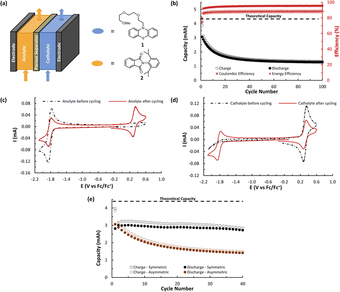
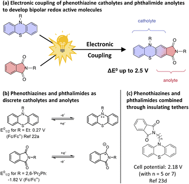
To test our strategy, we proposed the merger of the phenothiazine class of catholyte with the phthalimide class of anolyte. The favourable voltages of their redox couples and their high levels of electrochemical reversibility have resulted in these scaffolds being independently employed numerous times in asymmetric O-NRFB systems (Fig. 1b)7a,21,22 and in the context of BRMs through the use of electronically insulating linkers (Fig. 1c).23 However, the electronic merger of these two systems had not been explored and represented an excellent test case for our proposed strategy.
We began our studies by synthesizing a hybrid phenothiazine/phthalimide structure (N-MPhePhtha-1) bearing an N-methyl group on the phenothiazine portion and a 2,6-diisopropylphenyl moiety on the phthalimide. Data from cyclic voltammetry in 0.5 M TBAPF6/MeCN showed reversible oxidation (0.56 V vs. Fc/Fc+) and reduction (−1.81 V vs. Fc/Fc+) couples with a ΔE0 of 2.37 V across a range of scan rates (Fig. 2). This ΔE0 represents a 290 mV improvement in voltage as compared to batteries that can be made from analogous phenothiazine catholytes and phthalimide anolytes which are not electronically coupled (Fig. 1b). Unfortunately, the low solubility of N-MPhePhtha-1 in 0.5 M TBAPF6/MeCN (<5 mM) and in acetonitrile alone (26 ± 5 mM) prevented the study of longer-term cycling stability. In order to overcome solubility limitations, the imide and phenothiazine nitrogen atoms were used as easy points of synthetic modifications to introduce solubilizing groups such as poly ethers and ammonium salts. For each of these compounds, the voltage gap between oxidation and reduction was assessed through CV studies while electrochemical reversibility and stability were assessed via static galvanostatic charge–discharge cycling (100 cycles, 5 mM active material in 0.5 M TBAPF6/MeCN) in a 3-electrode H-cell equipped with a glass-frit separator (Fig. 3).
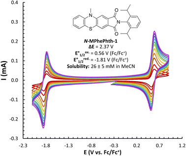 | ||
| Fig. 2 CV studies of N-MPhePhtha-1 (<5 mM in 0.5 M TBAPF6/MeCN) with scan rates varying from 50 to 1000 mV s−1. Solubility is an average of three measurements. | ||
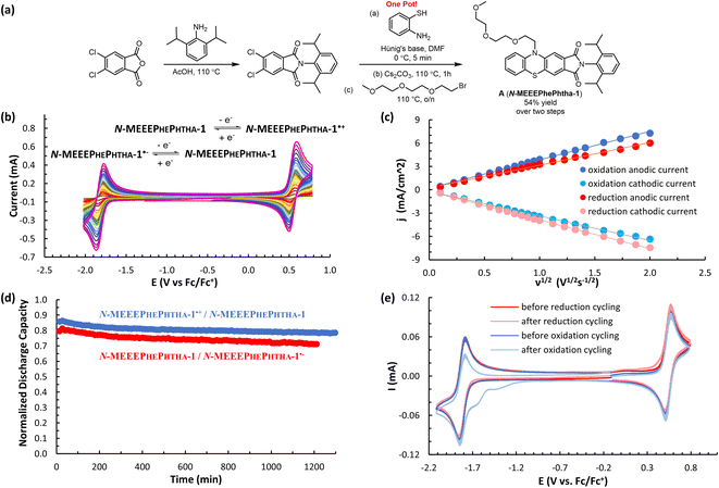
While all of these groups resulted in significantly improved solubility, A (N-MEEEPhePhtha-1), featuring an 2-(2-(2-methoxyethoxy)ethoxy)ethyl group on the phenothiazine nitrogen, proved especially attractive due to its high solubility (1430 ± 40 mM in MeCN), high stability towards reduction (0.51% normalized capacity loss per hour) and oxidation (0.38% normalized capacity loss per hour) (Fig. 3 and 4d), and its ease of synthetic accessibility via an operationally simple two-pot procedure from relatively inexpensive and commercially available starting materials (Fig. 4a). We further studied A (N-MEEEPhePhtha-1) through scan rate-dependent cyclic voltammetry and found oxidation and reduction to both be transport-limited redox processes (Fig. 4b and c) with an average diffusion coefficient of 6.3 × 10⁻⁶ cm2 s−1 as determined from the Randle–Ševčík equation and a heterogeneous electron-transfer rate of 8.3 × 10⁻² cm s−1 for oxidation and 8.2 × 10⁻² cm s−1 for reduction as determined by the Nicholson method.24 These data for the other compounds studied are available in the ESI.†
DFT calculations were then performed on A (N-MEEEPhePhtha-1), A (N-MEEEPhePhtha-1)˙−, and A (N-MEEEPhePhtha-1)˙+ to learn about their electronic structures and how they compare to analogously substituted phenothiazine 1 and phthalimide 2 lacking electronic coupling (Fig. 5). Qualitatively, the HOMO of A (N-MEEEPhePhtha-1) largely reflects that of phenothiazine 1, with minor additional contributions from the imide N. Likewise, the LUMO of A (N-MEEEPhePhtha-1) resembles that of phthalimide 2, with contributions to the orbital largely resulting from the imide and ring A with additional minor contributions from N-10 and ring C. Similar conclusions come from comparing SOMOs of the corresponding radical anions and cations. Quantitatively, our strategy of electronic coupling was calculated to have a beneficial impact of 340 mV on overall cell potential with 290 mV resulting from an increase in oxidation potential of A (N-MEEEPhePhtha-1) relative to phenothiazine 1 and just 50 mV resulting from a decrease in reduction potential of A (N-MEEEPhePhtha-1) relative to phthalimide 2 (see ESI† for details on calculations). This is in reasonable agreement with experimental CVs showing an improvement in theoretical cell potential of 220 mV, with all of this enhancement resulting from an increase in oxidation potential of A (N-MEEEPhePhtha-1) relative to phenothiazine 1 (vide infra, Fig. 6 and 7 for relevant CVs). These results, showing much of the beneficial improvement in cell potential of A (N-MEEEPhePhtha-1) resulting from an increase in its oxidation potential, may indicate that future efforts aimed at coupling phthalimide anolytes with more electron-donating catholyte fragments may result in even larger voltage enhancements by improving both the oxidation and reduction potentials of the hybrid molecules. Similar calculations on D (N-MEEEtBuPhePhtha-1) are available in the ESI.†
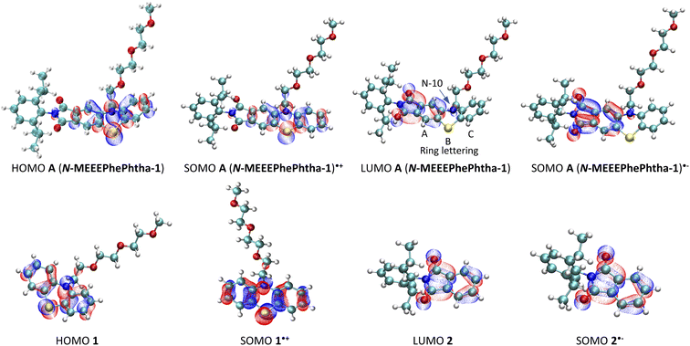 | ||
| Fig. 5 Frontier molecular orbitals for A (N-MEEEPhePtha-1), A (N-MEEEPhePtha-1)˙−, A (N-MEEEPhePtha-1)˙+, 1, 1˙+, 2, and 2˙−. | ||
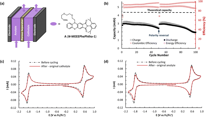
The ability of A (N-MEEEPhePhtha-1) to act as a BRM under flow conditions was next explored utilizing a flow battery design previously described by Brushett and coworkers (Fig. 6).22b,25 The battery was assembled utilizing a Daramic-175 porous separator and the catholyte and anolyte reservoirs were both filled with 6.5 mL of 25 mM A (N-MEEEPhePhtha-1) in 0.5 M TBAPF6/MeCN. Charging and discharging was performed at constant current densities of 10 mA cm−2 until reaching voltage cut offs ±350 mV from the cell's theoretical ΔE0 of 2.36 V. The utilization rate, based upon discharge capacity, reached a peak of 69.0% during cycle 5 and a capacity retention of 80% was observed after 50 cycles (Fig. 6b). At this point, the cell polarity was reversed in order to further highlight the bipolar nature of the BRM and an additional 50 charge–discharge cycles were performed. The reversal in polarity resulted in near complete recovery of lost capacity, reaching a utilization rate of 67.8% by cycle 56, which equates to 98.3% capacity retention. This ability to rebalance cells through a reversal in polarity and recover capacity loss due to chemical imbalances across the cell highlights an additional benefit of BRMs. At the end of 100 cycles, capacity retention was 64.3% relative to the peak discharge in cycle 5. Average coulombic efficiency was 94.6% while average energy efficiency was 85.3%. Post analysis CVs of the two reservoirs showed some evidence of decomposition by-products, as observed by shoulders on the oxidation redox couple and a reduction in peak currents as compared to that observed before flow cycling (Fig. 6c and d).
A (N-MEEEPhePhtha-1)'s hybrid phenothiazine-phthalimide nature also provided a unique opportunity to experimentally compare the performance of an O-NRFB featuring a BRM with that of an analogous battery setup in an asymmetric fashion featuring discrete anolyte (phthalimide) and catholyte (phenothiazine) molecules on opposing sides of the separator. To do so, an asymmetric battery was assembled utilizing phenothiazine 1 and phthalimide 2 with analogous N-substitution as A (N-MEEEPhePhtha-1) (Fig. 7a). These substitutions were conserved to ensure the results would allow for a direct comparison that better isolates the effect of symmetric BRM vs. asymmetric ROM flow batteries. By analogy to the symmetric flow battery, the catholyte reservoir was loaded with 6.5 mL of 25 mM phenothiazine 1 in 0.5 M TBAPF6/MeCN while the anolyte reservoir was loaded with 6.5 mL of 25 mM phthalimide 2 in 0.5 M TBAPF6/MeCN. Charging rates were 10 mA cm−2 with voltage cut offs ±350 mV from the cell's ΔE0 of 2.13 V. Peak utilization of 70.4% and overall coulombic (94.7%) and energy (87.8%) efficiencies were comparable to the performance of the symmetric flow battery featuring A (N-MEEEPhePhtha-1). However, a rapid decline in discharge capacity was observed following the first cycle in the asymmetric flow battery, with 50.2% capacity retention being reached after just 27 cycles. The rate of capacity decline then flattened until reaching a final 41.7% capacity retention after 100 cycles. Such a rapid decline in capacity that flattens with time is consistent with entropically-driven mixing of catholyte and anolyte materials until a homogenous mixture is obtained.9 This interpretation is supported by post-cycling CV analysis which shows a near uniform distribution of catholyte and anolyte across both battery reservoirs (Fig. 7c and d). These sets of experiments provide direct experimental evidence supporting the value of BRMs as a tool to reduce the impacts of crossover in O-NARFBs (Fig. 7e).
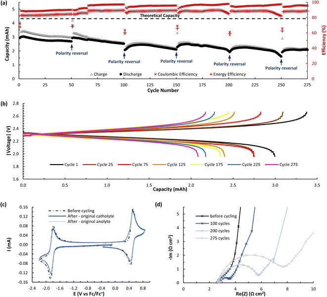
While A (N-MEEEPhePhtha-1) provided proof of principal that our PhePhtha molecules are capable of acting as BRMs in a flow battery environment, we sought to further improve long-term cycling stability. To do so, we turned our attention to D (N-MEEEtBuPhePhtha-1), which features a t-butyl group at the 7-position of the aromatic core. This structural modification was not only associated with higher cycling stability in H-cell galvanostatic charge–discharge experiments, but also resulted in improved solubility, likely due to increased steric repulsion reducing intermolecular pi-stacking (Fig. 3). A flow battery was setup under identical conditions as that with A (N-MEEEPhePhtha-1) and polarity reversals were similarly performed every 50 cycles. During flow operation, a peak utilization rate of 69.6% was obtained after 4 cycles. Consistent with the static H-cell data, D (N-MEEEtBuPhePhtha-1) showed significantly higher flow cycling stability with a capacity retention of 83.0% after 100 cycles. This retention represents a doubling of flow cycling stability as compared to A (N-MEEEPhePhtha-1) (64.3% capacity retention after 100 cycles). Flow cycling continued with D (N-MEEEtBuPhePhtha-1) for a total of 275 cycles, including 5 polarity reversals, with an average coulombic efficiency of 93.6%, an average energy efficiency of 86.8%, and a 275-cycle capacity retention of 68.6% (Fig. 8a). Post-cycling CVs indicate an average loss in concentration of ROM of just 17% over these 275 cycles based upon a comparison of peak currents before and after cycling (Fig. 8c). The higher capacity loss (31.4%) over 275 cycles as compared to the reduction in concentration of ROM (17%) can be explained via small leaks observed during the operation of the flow cell as well as by the potential formation of insoluble deposits on/within the separator and electrodes. The formation of such deposits is supported by electrochemical impedance spectroscopy which shows a consistent increase in cell resistance over the course of flow cell operation (Fig. 8d). There is some preliminary evidence from post cycling visual examination of membranes (see ESI Fig. SI-28†) that this fouling may be originating from the radical anion through either a direct interaction with the membrane or via a slowly accumulating decomposition product. This suggests that future work on optimizing this class of BRMs should focus on further improvements in radical anion stability as well as on better understanding causes of and strategies to mitigate membrane and electrode fouling.
Conclusions
In conclusion, we successfully implemented a strategy of electronically coupling phenothiazine catholytes with phthalimide anolytes by fusing a commonly shared aromatic ring to develop a new class of bipolar redox active molecules. The resulting PhenPhtha class of molecules possesses an increased cell potential when compared to the uncoupled parent molecules, with much of this improvement resulting from an increase in oxidation potential. Structure–activity studies found that solubility of these compounds could be greatly enhanced through the incorporation of a polyether group while both stability and solubility could be improved through the incorporation of a bulky t-butyl group. Successful symmetric battery performance was demonstrated under relevant flow conditions utilizing two PhenPhtha molecules. In the case of D (N-MEEEtBuPhePhtha-1), high levels of stability and efficiency were observed over 275 cycles and the bipolar nature of these molecules was highlighted through five polarity reversals within this demonstration. Finally, the hybrid nature of the PhenPhtha molecules allowed for a direct comparison to be made between symmetric redox flow batteries featuring BRMs and asymmetric flow batteries featuring distinct catholytes and anolytes separated on opposing sides of the battery. These results provide direct experimental support for the superior performance of symmetric battery construction in O-NRFBs which results from eliminating significant and irreversible capacity loss associated with crossover of ROMs in asymmetric cell constructions.Data availability
Experimental setups and procedures, characterization data, and computational details are available in the ESI.†Author contributions
Conceptualization of the project was performed by Jacob Tracy. Experiments were planned and conducted by Jacob Tracy and Elena Horst under the supervision of F. Dean Toste. Calculations were performed by Vladislav Roytman. Writing was done by Jacob Tracy and Elena Horst with review by F. Dean Toste.Conflicts of interest
There are no conflicts to declare.Acknowledgements
Support for this work was provided by the Joint Center for Energy Storage Research (JCESR), a Department of Energy, Energy Innovation Hub. We acknowledge Prof. Melanie S. Sanford and Ryan Walser-Kuntz, Prof. Fikile R. Brushett and Bertrand J. Neyhouse, as well as Prof. Shelley D. Minteer for helpful discussions regarding flow battery setup.Notes and references
- P. A. Owusu and S. Asumadu-Sarkodie, Cogent Engineering, 2016, 3, 1167990 CrossRef.
- Z. Yang, J. Zhang, M. C. W. Kintner-Meyer, X. Lu, D. Choi, J. P. Lemmon and J. Liu, Chem. Rev., 2011, 111, 3577–3613 CrossRef CAS PubMed.
- P. Alotto, M. Guarnieri and F. Moro, Renewable Sustainable Energy Rev., 2014, 29, 325–335 CrossRef CAS.
- (a) A. Cunha, J. Martins, N. Rodrigues and F. P. Brito, Int. J. Energy Res., 2015, 39, 889–918 CrossRef CAS; (b) K. Lourenssen, J. Williams, F. Ahmadpour, R. Clemmer and S. Tasnim, J. Energy Storage, 2019, 25, 100844 CrossRef.
- Y. Ding, C. Zhang, L. Zhang, Y. Zhou and G. Yu, Chem. Soc. Rev., 2018, 47, 69–103 RSC.
- For a small selection of recent reviews on the topic, see: (a) J. Winsberg, T. Hageman, T. Janoschka, M. D. Hager and U. S. Schubert, Angew. Chem. Int. Ed., 2017, 56, 686–711 ( Angew. Chem. , 2017 , 129 , 702–729 ) CrossRef CAS PubMed; (b) P. Leung, A. A. Shah, L. Sanz, C. Flox, J. R. Morante, Q. Xu, M. R. Mohamed, C. Ponce de León and F. C. Walsh, J. Power Sources, 2017, 360, 243–283 CrossRef CAS; (c) C. H. Armstrong and K. E. Toghill, Electrochem. Commun., 2018, 91, 19–24 CrossRef CAS; (d) M. Li, Z. Rhodes, J. R. Cabrera-Pardo and S. D. Minteer, Sustainable Energy Fuels, 2020, 4, 4370–4389 RSC; (e) Z. Zhao, C. Zhang and X. Li, J. Energy Chem., 2022, 67, 621–639 CrossRef.
- For selected examples of high voltage “asymmetric” flow batteries (>2.9 V) see: (a) Y. Yan, S. G. Robinson, M. S. Sigman and M. S. Sanford, J. Am. Chem. Soc., 2019, 141, 15301–15306 CrossRef CAS PubMed; (b) X. Xing, Q. Liu, W. Xu, W. Liang, J. Liu, B. Wang and J. P. Lemmon, ACS Appl. Energy Mater., 2019, 2, 2364–2369 CrossRef CAS; (c) X. Xing, Q. Liu, B. Wang, J. P. Lemmon and W. Q. Xu, J. Power Sources, 2020, 445, 227330 CrossRef CAS.
- (a) M. L. Perry, J. D. Saraidaridis and R. M. Darling, Curr. Opin. Electrochem., 2020, 21, 311–318 CrossRef CAS; (b) F. Zhong, M. Yang, M. Ding and C. Jia, Front. Chem., 2020, 8, 451 CrossRef CAS PubMed.
- Z. Liang, N. H. Attanayake, K. V. Greco, B. J. Neyhouse, J. L. Barton, A. P. Kaur, W. L. Eubanks, F. R. Brushett, J. Landon and S. A. Odom, ACS Appl. Energy Mater., 2021, 4, 5443–5451 CrossRef CAS.
- A. Shrestha, K. H. Hendriks, M. S. Sigman, S. B Minteer and M. S. Sanford, Chem.–Eur. J., 2020, 26, 5369–5373 CrossRef CAS PubMed.
- J. Sheng, A. Mukhopadhyay, W. Wang and H. Zhu, Mater. Today Nano, 2019, 7, 100044 CrossRef.
- J. Yuan, Z.-Z. Pan, Y. Jin, Q. Qiu, C. Zhang, Y. Zhao and Y. Li, J. Power Sources, 2021, 500, 229983 CrossRef CAS.
- For a recent review, see: Y. Y. Lai, X. Li and Y. Zhu, ACS Appl. Polym. Mater., 2020, 2, 113–128 CrossRef CAS.
- For selected seminal examples of the use of polymers to reduce crossover see: (a) G. Nagarjuna, J. Hui, K. J. Cheng, T. Lichtenstein, M. Shen, J. S. Moore and J. Rodríguez-López, J. Am. Chem. Soc., 2014, 136, 16309–16316 CrossRef CAS PubMed; (b) T. Sukegawa, I. Masuko, K. Oyaizu and H. Nishide, Macromolecules, 2014, 47, 8611–8617 CrossRef CAS; (c) E. C. Montoto, G. Nagarjuna, J. Hui, M. Burgess, N. M. Sekerak, K. Hernández-Burgos, T.-S. Wei, M. Kneer, J. Grolman, K. J. Cheng, J. A. Lewis, J. S. Moore and J. Rodríguez-López, J. Am. Chem. Soc., 2016, 138, 13230–13237 CrossRef CAS PubMed; (d) E. C. Montoto, G. Nagarjuna, J. S. Moore and J. Rodríguez-López, J. Electrochem. Soc., 2017, 164, A1688–A1694 CrossRef CAS.
- For selected seminal examples of the use of oligomers to reduce crossover see: (a) S. E. Doris, A. L. Ward, A. Baskin, P. D. Frischmann, N. Gavvalapalli, E. Chénard, C. S. Sevov, D. Prendergast, J. S. Moore and B. A. Helms, Angew. Chem. Int. Ed., 2017, 56, 1595–1599 ( Angew. Chem. , 2017 , 129 , 1617–1621 ) CrossRef CAS PubMed; (b) K. H. Hendricks, S. G. Robinson, M. N. Braten, C. S. Sevov, B. A. Helms, M. S. Sigman, S. D. Minteer and M. S. Sanford, ACS Cent. Sci., 2018, 4, 189 CrossRef PubMed; (c) M. J. Baran, M. N. Braten, E. C. Montoto, Z. T. Gossage, L. Ma, E. Chénard, J. S. Moore, J. Rodríguez-López and B. A. Helms, Chem. Mater., 2018, 30, 3861–3866 CrossRef CAS.
- For selected examples of eutectic electrolytes see: (a) C. Zhang, L. Zhang, Y. Ding, X. Guo and G. Yu, ACS Energy Lett., 2018, 3, 2875–2883 CrossRef CAS; (b) C. Zhang, Y. Qian, Y. Ding, L. Zhang, X. Guo, Y. Zhao and G. Yu, Angew. Chem. Int. Ed., 2019, 58, 7045–7050 ( Angew. Chem. , 2019 , 131 , 7119–7124 ) CrossRef CAS PubMed.
- (a) M. Li, J. Case and S. D. Minteer, ChemElectroChem, 2021, 8, 1215–1232 CrossRef CAS; (b) G. S. Nambafu, Electrochem. Commun., 2021, 127, 107052 CrossRef.
- For examples of lower voltage (<2 V Ecell) BRMs not reliant upon electronically insulating tethers see: (a) W. Duan, R. S. Vemuri, J. D. Milshtein, S. Laramie, R. D. Dmello, J. Huang, L. Zhang, D. Hu, V. Vijayakumar, W. Wang, J. Liu, R. M. Darling, L. Thompson, K. Smith, J. S. Moore, F. R. Brushett and X. Wei, J. Power Sources, 2016, 4, 5448–5456 CAS; (b) R. A. Potash, J. R. McKone, S. Conte and H. D. Abruña, J. Electrochem. Soc., 2016, 163, A338–A344 CrossRef CAS; (c) J. Winsberg, T. Hagemann, S. Muench, C. Friebe, B. Häupler, T. Janoschka, S. Morgenstern, M. D. Hager and E. S. Schubert, Chem. Mater., 2016, 28, 3401–3405 CrossRef CAS; (d) A. M. Kosswattaarachchi, A. E. Friedman and T. R. Cook, ChemSusChem, 2016, 9, 3317–3323 CrossRef CAS PubMed; (e) K. H. Hendriks, C. S. Sevov, M. E. Cook and M. S. Sanford, ACS Energy Lett., 2017, 2, 2430–2435 CrossRef CAS; (f) T. Hagemann, J. Winsberg, B. Häupler, T. Janoschka, J. J. Gruber, A. Wild and U. S. Schubert, NPG Asia Mater., 2017, 9, e340 CrossRef CAS; (g) C. G. Armstrong, R. W. Hogue and K. E. Toghill, J. Power Sources, 2019, 440, 227037 CrossRef CAS; (h) G. D. Charlton, S. M. Barbon, J. B. Gilroy and C. A. Dyker, J. Energy Chem., 2019, 34, 52–56 CrossRef; (i) A. Korshunov, M. J. Milner, M. Grünebaum, A. Studer, M. Winter and I. Cekic-Laskovic, J. Mater. Chem. A, 2020, 8, 22280–22291 RSC; (j) O. A. Levitskiy, A. V. Bogdanov, I. A. Klimchuk and T. V. Magdesieva, ChemPlusChem, 2022, 87, e202100508 CrossRef CAS PubMed; (k) J. S. Steen, J. L. Nuismer, V. Eiva, A. E. T. Wiglema, N. Daib, J. Hjelm and E. Otten, J. Am. Chem. Soc., 2022, 144, 5051–5058 CrossRef CAS PubMed.
- For examples of high voltage (>2 V Ecell) BRMs not reliant upon electronically insulating tethers see: (a) S. H. Oh, C.-W. Lee, D. H. Chun, J.-D. Jeon, J. Shim, K. H. Shin and J. H. Yang, J. Mater. Chem. A, 2014, 2, 19994–19998 RSC; (b) T. Hagemann, J. Winsberg, A. Wild and U. S. Schubert, Electrochim. Acta, 2017, 228, 494–502 CrossRef CAS; (c) T. Ma, Z. Pan, L. Miao, C. Chen, M. Han, Z. Shang and J. Chen, Angew. Chem. Int. Ed., 2018, 57, 3158–3162 ( Angew. Chem. , 2018 , 130 , 3212–3216 ) CrossRef CAS PubMed; (d) P. Geysens, Y. Li, I. Wankelecom, J. Fransaer and K. Binnemans, ACS Sustainable Chem. Eng., 2020, 8, 3832–3843 CrossRef CAS; (e) J. Moutet, J. M. Veleta and T. L. Gianetti, ACS Appl. Energy Mater., 2021, 4, 9–14 CrossRef CAS; (f) J. Moutet, D. Mills, M. M. Hossain and T. L. Gianetti, Mater. Adv., 2022, 3, 216–223 RSC; (g) Y. Liu, G. Dai, Y. Chen, R. Wang, H. Li, X. Shi, X. Zhang, Y. Xu and Y. Zhao, ACS Energy Lett., 2022, 7, 1274–1283 CrossRef CAS PubMed; (h) D. Xu, C. Zhang and Y. Li, Chem. Eng. J., 2022, 439, 135766 CrossRef CAS.
- R. P. Fornari, M. Mesta, J. Hjelm, T. Vegge and P. de Silva, ACS Mater. Lett., 2020, 2, 239–246 CrossRef CAS.
- For selected examples of flow batteries employing phthalimide derivatives, see ref. 7a and: (a) Z. Li, S. Liu, K. Huang, D. Fang, F. Wang and S. Peng, Electrochem. Solid-State Lett., 2011, 14, A171–A173 CrossRef CAS; (b) X. Wei, W. Duan, J. Huang, L. Zhang, B. Li, D. Reed, W. Xu, V. Sprenkle and W. Wang, ACS Energy Lett., 2016, 1, 705–711 CrossRef CAS; (c) J. Winsberg, S. Benndorf, A. Wild, M. D. Hager and Y. S. Schubert, Macromol. Chem. Phys., 2018, 219, 1700267 CrossRef; (d) H.-S. Kim, S. Hwang, Y. Kim, J. H. Ryu, S. M. Oh and K. J. Kim, APL Mater., 2018, 6, 047901 CrossRef; (e) A. M. Kosswattaarachchi and T. R. Cook, J. Electrochem. Soc., 2018, 165, A194–A200 CrossRef CAS; (f) C. Zhang, Z. Niu, Y. Ding, L. Zhang, Y. Zhou, X. Guo, X. Zhang, Y. Zhao and G. Yu, Chem, 2018, 4, 2814–2825 CrossRef CAS; (g) C. Zhang, Y. Qian, Y. Ding, L. Zhang, X. Guo, Y. Zhao and G. Yu, Angew. Chem. Int. Ed., 2019, 58, 7045–7050 ( Angew. Chem. , 2019 , 131 , 7119–7124 ) CrossRef CAS PubMed; (h) N. Daub, R. A. J. Janssen and K. H. Hendriks, ACS Appl. Energy Mater., 2021, 4, 9248–9257 CrossRef CAS; (i) H. Chen, Z. Niu and Y. Zhao, Electrochem. Commun., 2021, 126, 107028 CrossRef CAS.
- For selected examples of flow batteries employing phenothiazine derivatives, see: (a) A. P. Kaur, N. E. Holubowitch, S. Ergun, C. F. Elliott and S. A. Odom, Energy Technol., 2015, 3, 476–480 CrossRef CAS; (b) J. A. Kowalki, M. D. Casselman, A. P. Kaur, J. D. Milshtein, C. F. Elliott, S. Modekrutti, N. H. Attanayake, N. Zhang, S. R. Parkin, C. Risko, F. R. Brushett and S. A. Odom, J. Mater. Chem. A, 2017, 5, 24371–24379 RSC; (c) N. H. Attanayake, J. A. Kowalski, K. V. Greco, M. D. Casselman, J. D. Milshtein, S. J. Chapman, S. R. Parkin, F. R. Brushett and S. A. Odom, Chem. Mater., 2019, 31, 4353–4363 CrossRef CAS; (d) C. Zhang, Z. Niu, S. Peng, Y. Ding, L. Zhang, X. Guo, Y. Zhao and G. Yu, Adv. Mater., 2019, 31, 1901052 CrossRef PubMed; (e) J. Chai, A. Lashgari, X. Wang, C. K. Williams and J. J. Jiang, J. Mater. Chem. A, 2020, 8, 15715–17524 RSC; (f) N. H. Attanayake, Z. Liang, Y. Wang, A. P. Kaur, S. R. Parkin, J. K. Mobley, R. H. Ewoldt, J. Landon and S. A. Odom, Mater. Adv., 2021, 12, 1390–1401 RSC; (g) Y. Yan, S. G. Robinson, T. P. Vaid, M. S. Sigman and M. S. Sanford, J. Am. Chem. Soc., 2021, 143, 13450–13459 CrossRef CAS PubMed; (h) Y. Yan, B. V. Vogt, T. P. Vaid, M. S. Sigman and M. S. Sanford, Angew. Chem. Int. Ed., 2021, 60, 27039–27045 ( Angew. Chem. , 2021 , 133 , 27245–27251 ) CrossRef CAS PubMed.
- (a) S. Hwang, H.-S. Kim, J. H. Ryu and S. M. Oh, J. Power Sources, 2018, 395, 60–65 CrossRef CAS; (b) S. Hwang, H.-S. Kim, J. H. Ryu and S. M. Oh, J. Power Sources, 2019, 421, 1 CrossRef CAS; (c) D. Xu, C. Zhang, Y. Zhen and Y. Li, ACS Appl. Energy Mater., 2021, 4, 8045–8051 CrossRef CAS; (d) M. Li, G. Agarwal, I. A. Shkrob, R. T. VanderLinden, J. Case, M. Prater, Z. Rhodes, J. S. Assary and S. D. Minteer, J. Mater. Chem. A, 2021, 9, 23563–23573 RSC; (e) G. S. Nambafu, E. P. Delmo, E. B. Shahid, C. Zhang, Q. Chen, T. Zhao, P. Gao, K. Amine and M. Shao, Nano Energy, 2022, 94, 106963 CrossRef CAS.
- (a) R. S. Nicholson, Anal. Chem., 1965, 37, 1351–1355 CrossRef CAS; (b) I. Lavagnini, R. Antiochia and F. Magno, Electroanalysis, 2004, 16, 505–506 CrossRef CAS.
- See ref. 22b and (a) J. D. Milshtein, J. L. Barton, R. M. Darling and F. R. Brushett, J. Power Sources, 2016, 327, 151–159 CrossRef CAS; (b) J. D. Milshtein, K. M. Tenny, J. L. Barton, J. Drake, R. M. Darling and F. R. Brushett, J. Electrochem. Soc., 2017, 164, E3265–E3275 CrossRef CAS; (c) J. D. Milshtein, E. L. Fisher, T. M. Breault, L. T. Thompson and F. R. Brushett, ChemSusChem, 2017, 10, 2080–2088 CrossRef CAS PubMed; (d) J. D. Milshtein, J. L. Barton, T. J. Carney, J. A. Kowalski, R. M. Darling and F. R. Brushett, J. Electrochem. Soc., 2017, 164, A2487–A2499 CrossRef CAS.
Footnotes |
| † Electronic supplementary information (ESI) available. See https://doi.org/10.1039/d2sc03450f |
| ‡ These authors contributed equally to this work. |
| This journal is © The Royal Society of Chemistry 2022 |


![[thin space (1/6-em)]](https://www.rsc.org/images/entities/char_2009.gif) :
: