 Open Access Article
Creative Commons Attribution 3.0 Unported Licence
A Sn-stabilized Cuδ+ electrocatalyst toward highly selective CO2-to-CO in a wide potential range†
Xingxing
Tan
ab,
Weiwei
Guo
abc,
Shoujie
Liu
 d,
Shunhan
Jia
 ab,
Liang
Xu
a,
Jiaqi
Feng
a,
Xupeng
Yan
ab,
Chunjun
Chen
ab,
Liang
Xu
a,
Jiaqi
Feng
a,
Xupeng
Yan
ab,
Chunjun
Chen
 a,
Qinggong
Zhu
 a,
Xiaofu
Sun
 *ab and
Buxing
Han
 *abe
*abe
aBeijing National Laboratory for Molecular Sciences, CAS Key Laboratory of Colloid and Interface and Thermodynamics, CAS Research/ Education Center for Excellence in Molecular Sciences, Institute of Chemistry, Chinese Academy of Sciences, Beijing 100190, P. R. China. E-mail: sunxiaofu@iccas.ac.cn; hanbx@iccas.ac.cn
bSchool of Chemical Sciences, University of Chinese Academy of Sciences, Beijing 100049, P. R. China
cCollege of Chemistry and Chemical Engineering, Qingdao University, Qingdao 266071, P. R. China
dChemistry and Chemical Engineering of Guangdong Laboratory, Shantou 515063, P. R. China
eShanghai Key Laboratory of Green Chemistry and Chemical Processes, School of Chemistry and Molecular Engineering, East China Normal University, Shanghai 200062, P. R. China
First published on 26th September 2022
Abstract
Current techno-economic evaluation manifests that the electrochemical CO2 reduction reaction (eCO2RR) to CO is very promising considering its simple two-electron transfer process, minimum cost of electricity, and low separation cost. Herein, we report a Sn-modification strategy that can tune the local electronic structure of Cu with an appropriate valence. The as-prepared catalysts can alter the broad product distribution of Cu-based eCO2RR to predominantly generate CO. CO faradaic efficiency (FE) remained above 96% in the wide potential range of −0.5 to −0.9 V vs. the reversible hydrogen electrode (RHE) with CO partial current density up to 265 mA cm−2. The catalyst also had remarkable stability. Operando experiments and density functional theory calculations demonstrated that the surface Cuδ+ sites could be modulated and stabilized after introducing Sn. The Cuδ+ sites with low positive valence were conducive to regulating the binding energy of intermediates and resulted in high CO selectivity and maintained the stability of the catalyst. Additionally, scaling up the catalyst into a membrane electrode assemble system (MEA) could achieve a high overall current of 1.3 A with exclusive and stable CO generation.
Introduction
The electrochemical CO2 reduction reaction (eCO2RR) to value-added chemicals and fuels provides a sustainable route for storing renewable electrical energy and closing the carbon loop.1–5 CO2 can be converted to various products via different H+/e− transfer numbers and reduction pathways. Among them, CO is a component for syngas, which has been widely used in the chemical synthesis of a range of organic products such as alcohol, olefins, and aromatics based on the Fischer–Tropsch route.6,7 The eCO2RR is a potential substitute technology for CO production due to the high cost and high energy consumption of the traditional methods (e.g. reverse water gas shift reaction and natural gas reformation).8–10 Despite recent improvements on exploiting various electrocatalysts and electrolytes,11–14 the scaling up of the eCO2RR to CO for practical applications is still in its infancy with a few urgent issues to be solved such as high catalyst cost, high overpotential, narrow potential window, low current density, as well as poor long-term stability.The 2H+/2e− reaction process of CO2-to-CO involves multiple steps, including the formation of *COOH, the dissociation of *COOH to *CO and CO desorption.15,16 Thus, an ideal catalyst for CO2-to-CO should have appropriate adsorption strengths for *COOH and *CO. As an abundant, cheap, and less toxic element, Cu is a good candidate for the substitution of noble metals in practical application.17,18 A Cu-based catalyst is also the most promising catalyst for the eCO2RR, and surface Cuδ+ (0 < δ < 1) sites have been suggested as active sites.19–21 However, a Cu catalyst is capable of converting CO2 to a range of reduced products (CO, hydrocarbons, and oxygenates),10,22 giving rise to poor selectivity for a specific product, especially for CO. Moreover, it suffers from low yields and catalyst durability issues under electrochemical conditions.23 Therefore, there is a strong need for developing an efficient strategy to optimize the intermediate binding strength on Cuδ+ sites and reduce the tendency of Cuδ+ reduction at negative potentials.
Introducing modifier elements into Cu has been shown to be a promising route to achieve high selectivity for the eCO2RR. Prior studies showed that some non-metallic elements (e.g., boron and halides)19,22 and metals (e.g., Au and Pd)24–26 can tune the local electronic structure of Cu with an appropriate valence to meet the demands for diverse products. p-Block metals (pM), such as In, Sn, and Pb, possess O affinity and high overpotential for the H2 evolution reaction (HER).27–30 Doping pM into Cu may prefer to bond with O in *COOH,31 which benefits *COOH dissociation to form *CO. Moreover, it can also suppress the undesirable HER. On the other hand, the gas diffusion electrode (GDE) has shorter gas diffusional lengths and higher concentrations of gaseous feeds,12,32 resulting in higher current densities. Thus, constructing an appropriate pM-Cu GDE may realize high selectivity and activity for CO2-to-CO.
Herein, we have constructed a Sn-modified Cu electrocatalyst that can significantly enhance the CO2-to-CO activity and selectivity with high FE over a wide potential range. Experimental and density-functional theory (DFT) studies indicated that the introduction of Sn could modulate the local electronic structure of the Cu-based catalyst and stabilize the oxidation states of Cu during the eCO2RR process. Cu0 was replaced by Cuδ+ sites with appropriate valence during the eCO2RR after introducing Sn. The resulting Cuδ+ sites could facilitate CO2 activation and CO formation. Besides, scaling up the electrode into a modular cell could achieve a very high current with exclusive and stable CO generation.
Results and discussion
eCO2RR performance in a flow cell
Sn-modified Cu catalysts were fabricated by a facile coprecipitation method followed by annealing at 600 °C for 2 h under an argon atmosphere. The obtained catalysts had Sn contents of 0, 0.6, 2.9, and 4.0 wt%, which were determined by inductively coupled plasma optical emission spectroscopy (ICP-OES). We denoted them as Cu–O, 0.6%Sn–Cu–O, 2.9%Sn–Cu–O, and 4.0%Sn–Cu–O for clarity. The electrocatalytic CO2 reduction performances were evaluated in a flow cell with 1 M KOH aqueous solution as electrolyte. The as-prepared catalyst inks were air-brushed on carbon paper with a hydrophobic microporous gas diffusion layer, which was used as the GDE.The gas and liquid products were quantified by using gas chromatography (GC) and 1H nuclear magnetic resonance (NMR) spectroscopy, respectively. Cu–O showed a poor product selectivity with a mixture of H2, CO, formate, and C2 products (Fig. 1A and S1†). Doping Sn into CuO significantly improved the performance for CO2 reduction to CO. All the catalysts presented a combined product FE of around 100% in the potential range from −0.35 to −1.0 V versus RHE. It can be clearly observed that the addition of Sn could boost the activity and selectivity for CO formation, and 2.9%Sn–Cu–O exhibited the best performance (Fig. 1A, B and S2†). The change in applied potential from −0.35 V to −0.9 V over 2.9%Sn–Cu–O led to a variation in CO partial current density in a broad range from 24 to 265 mA cm−2, and the FE remained over 96% in the potential range of 0.5 to 0.9 V vs. RHE. This wide potential window is essential for expanding the eCO2RR process into practical applications, which is expected to enhance robustness and stability when inherent potential fluctuation occurs. However, as the Sn content was further increased up to 4.0 wt%, the main product was switched to formate, while the conversion of CO2 to CO was suppressed.
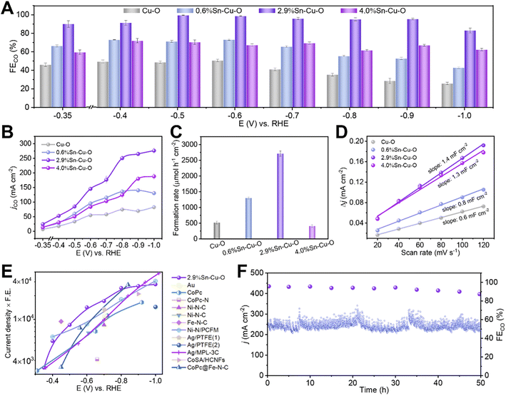 | ||
| Fig. 1 Electrocatalytic CO2RR performances. (A) The FECO and (B) jCO at different applied potentials over Cu–O, 0.6%Sn–Cu–O, 2.9%Sn–Cu–O, and 4.0%Sn–Cu–O catalysts. (C) The formation rates of the CO product at the potentials with optimum CO selectivity over Cu–O, 0.6%Sn–Cu–O, 2.9%Sn–Cu–O, and 4.0%Sn–Cu–O catalysts. (D) The charging current density differences plotted against scan rates. (E) Overview of different catalysts' performance in flow cells reported so far (see Table S2† for details). (1) and (2) in (E) represent the electrocatalytic reactions conducted in KHCO3 and KOH, respectively. (F) The stability of 2.9%Sn–Cu–O obtained at −0.8 V. | ||
The formation rate of CO was also affected significantly by the Sn content. As presented in Fig. 1C, it can reach 2710 μmol h−1 cm−2 over 2.9%Sn–Cu–O at −0.6 V, which was roughly 5.2, 2.1 and 6.6 times higher than that of Cu–O, 0.6%Sn–Cu–O, and 4.0%Sn–Cu–O, respectively. We further normalized the CO formation rate based on the electrochemical surface area (ECSA), which was measured via the double-layer capacitance method (Fig. 1D and S3†). As a result, the normalized CO formation rate had the same sequence of 2.9%Sn–Cu–O > 0.6%Sn–Cu–O > Cu–O > 4.0%Sn–Cu–O at all the applied potentials (Fig. S4†).
The catalytic activity was then compared with that of the state-of-the-art catalysts by multiplying current density (activity) by CO formation FE (selectivity). It can be seen that the performance of 2.9%Sn–Cu–O was higher than many other reported catalysts at a lower overpotential (Fig. 1E, Tables S1 and S2†). Furthermore, the 2.9%Sn–Cu–O catalyst also displayed excellent stability and no obvious change in current density and FE was observed during the eCO2RR at −0.8 V for 50 h (Fig. 1F). Therefore, it is worth mentioning that the 2.9%Sn–Cu–O catalyst exhibited high selectivity for CO at a high current density in a wide operation window, which is very promising for application of the eCO2RR to CO.
Ex situ characterization studies
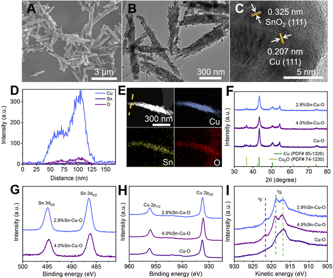
The scanning electron microscopy (SEM), transmission electron microscopy (TEM), and powder X-ray diffraction (XRD) measurements clarified that Sn-modified CuO was formed with a rod-like structure after coprecipitating and annealing (Fig. S5–S9†). The actual catalyst was then formed in situ at the beginning of the electrochemical reduction, which will be further discussed in the following sections. The SEM and TEM images in Fig. 2A and B show that the morphology of 2.9%Sn–Cu–O remained almost unchanged with a length of 2.4 ± 0.6 μm and a diameter of 120 ± 40 nm. The high resolution TEM (HRTEM) image exhibited a lattice spacing of 0.207 nm and 0.325 nm, which can be ascribed to the Cu(111) and SnO2(110) planes,33,34 respectively (Fig. 2C). The line-scan analysis and element mapping analysis were then carried out, suggesting that Cu, Sn, and O elements dispersed uniformly over the catalyst (Fig. 2D and E). The Sn content measured by TEM energy-dispersive X-ray spectroscopy (EDS) for 2.9%Sn–Cu–O was 2.7 wt%, which was close to that obtained by ICP-OES. The TEM images of other catalysts after the reaction can be seen in Fig. S10† The XRD patterns in Fig. 2F showed that CuO was reduced in situ in the eCO2RR process. The diffraction peaks at 43.4°, 50.5°, 74.2°, and 36.5° can be assigned to the Cu(111), (200), (220), and Cu2O(111) planes, respectively. The characteristic peaks of SnO2 were not found due to its low loadings. The CO2 adsorption isotherms (Fig. S11†) showed that higher CO2 adsorption capability was acquired after introduction of Sn into CuO, while a similar CO2 adsorption capability was found in Sn-modified catalysts with different Sn contents. The difference in selectivity and activity may be attributed to the local electron structure of Cu and Sn in the as-prepared catalysts.Quasi-in situ X-ray photoelectron spectroscopy (XPS) was performed to investigate the composition and valence state of the catalysts (Fig. S12†). As shown in Fig. 2G, the binding energy of 486.4 eV for Sn 3d5/2 was attributed to SnO2, which showed no obvious change in the Sn 3d region after the eCO2RR (Fig. 2G and S13†).35 XPS depth profiling analysis using an argon cluster beam and Ar+ to etch layers of the surface or surface contamination was performed to reveal subsurface information. As shown in Fig. S13C and D,† the XPS depth profiling analysis result exhibited a doublet with the main peak for the Sn 3d5/2 component at a binding energy 486.5 eV after the eCO2RR, which was in agreement with the value for SnO2. No new peaks of Sn2+ and Sn0 can be found. There was also no obvious change in the Sn 3d region after different times of Ar+ beam etching (the etching depth was estimated to be 30 to 380 nm). It indicated that the oxidation states of Sn did not undergo considerable change during electrocatalysis. Fig. S14 and S15† show that all the catalysts exhibited obvious Cu2+ features with strong satellite peaks at 943.0 eV and higher binding energies of Cu 2p3/2 at 933.7 eV before electrolysis.36 These results confirmed that both Cu and Sn in the matrix exist in their oxide states (Cu2+ and Sn4+) before electrolysis. However, the Cu 2p region for all the catalysts exhibited a shift toward lower binding energies after CO2 electrolysis (Fig. 2H and S14†), and the Cu Auger L3M45M45 transition spectra (3F and 1G) showed the valence configuration of Cu+ (with a 1G peak at 916.8 eV) and Cu0 (with a 1G peak at 918.8 eV and a distinct 3F peak) (Fig. 2I).37,38 The results revealed that CuO was reduced during the eCO2RR.
Operando measurements
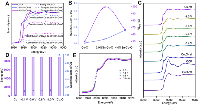
Operando X-ray absorption spectroscopy (XAS) was conducted to further investigate the detailed structural information and evolution process of catalysts during CO2 reduction (Fig. S16†). Similarly, the X-ray absorption near-edge structure (XANES) spectra at the Cu K-edge showed the typical features of the CuO reference (CuO-ref), indicating that Cu2+ was dominant in these three catalysts before the eCO2RR (Fig. S17†). As the cathodic potential was applied, the Cu oxides in the catalysts were reduced (Fig. S18†). Only features consistent with metallic Cu were detected in Cu–O, implying that Cu2+ was fully reduced to Cu0. However, the absorption edges of 2.9%Sn–Cu–O and 4.0%Sn–Cu–O resided between that of metallic Cu (Cu-ref) and the Cu2O reference (Cu2O-ref).To estimate the Cu oxidation state more intuitively, a linear combination fitting analysis of the operando XANES data was performed using Cu foil and Cu2O as the reference spectra. The results suggested that the fraction of Cu0 species was increased from 10% to 27% as the Sn content varied from 2.9 to 4.0% (Fig. 3A and B), indicating that the introduction of Sn could modulate the oxidation state of Cu-based catalysts during the eCO2RR. This modulation effect likely stems from the moderate electronegativity of Sn4+ (1.73), which is between that of Cu0 (1.9) and Cu+ (1.56). Remarkably, it was found that the catalytic activity followed a volcano-shaped trend for the eCO2RR to CO with respect to the Cu oxidation state (Fig. 3B). The highest FECO of 99.5% was achieved at the Cu valence state of +0.1. We also estimated the Cu oxidation state as a function of the Cu K-edge energy shift and found that the Cu oxidation state in 2.9%Sn–Cu–O catalysts remained at around +0.1 at different cathodic potentials (Fig. 3C). Similar conclusions were also demonstrated by operando X-ray emission spectroscopy (XES), as the Cu Kβ lines are sensitive to the changes in the spin state and oxidation state. Similar Kβ1,3 energies were presented, implying that the oxidation state of Cu did not undergo considerable change at different cathode potentials (Fig. 3D). These results indicated the robustness of the oxidation state of Cu, which was attributed to the introduction of Sn.
Interestingly, similar FEs up to ∼90% were maintained in the catalytic activity toward CO2 reduction to CO at −0.4, −0.6, and −0.8 V vs. RHE, indicating that the stable Cuδ+ species (δ = 0.1) played a key role in the eCO2RR. A slight decrease in the FECO was observed at −1.0 V accompanied by an increase in FE of H2, which was attributed to the enhanced competitive HER at a high cathodic potential. The in situ Cu XANES spectra of 2.9%Sn–Cu–O catalyst at different time points were also recorded to observe the changes in the Cu oxidation state. As shown in Fig. 3E, similar Cu oxidation states of ∼+0.1 were observed after 15 min, 0.5 h, 1.5 h, and 2.5 h of operation at −0.6 V vs. RHE, implying that Cu2+ was reduced at beginning of electrolysis and the reduced Cuδ+ species were stable during the eCO2RR.
DFT calculations
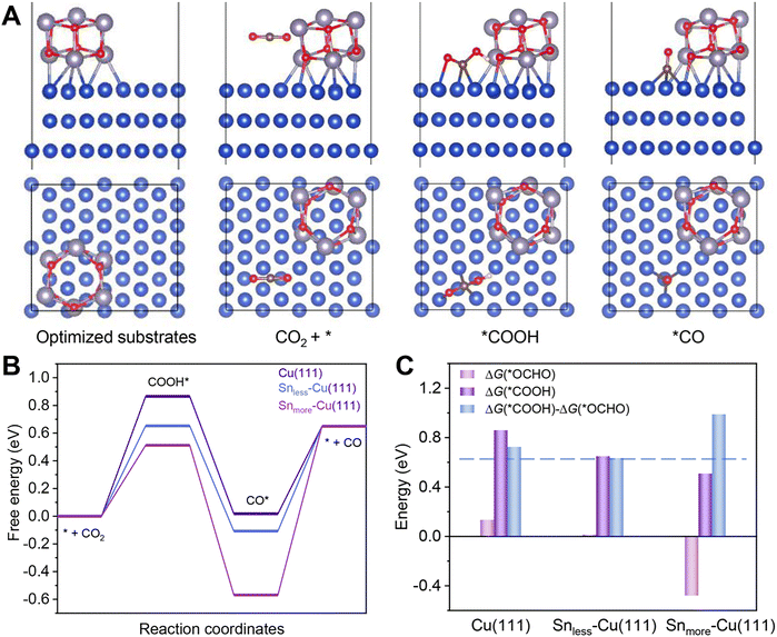
DFT calculations were carried out to gain insight into the excellent performance of 2.9%Sn–Cu–O for CO2 reduction to CO. According to the HRTEM image and XRD patterns, we used the Cu(111) facet to represent Cu–O. Snless–Cu(111) and Snmore–Cu(111) stand for 2.9%Sn–Cu–O and 4.0%Sn–Cu–O, respectively. All the computational structure models and the detailed data can be found in Fig. S20–S27 and Table S3.† The catalytic pathway of CO2-to-CO is illustrated in Fig. 4A. In general, *COOH and *CO are recognized as key intermediates in this 2H+/2e− reaction process.1,39 The formation of *COOH on these models was endergonic, and the Gibbs free energy on Snless–Cu(111) and Snmore–Cu(111) was 0.21 eV and 0.35 eV lower than that on Cu(111) (Fig. 4B). This indicated that the introduction of Sn enabled a decrease in the energy barrier of CO2 activation. Afterwards, the formation of *CO from *COOH was exergonic. Finally, CO desorption was highly endergonic, and acted as the rate-determining step (RDS) for Snless–Cu(111) and Snmore–Cu(111). It was quite different from prisitine Cu, in which *COOH formation was the RDS. Based on the simulation, the Gibbs free energy of the RDS on Snless–Cu(111) was 0.46 eV and 0.1 eV lower than that on Snmore–Cu(111) and Cu(111), respectively. It demonstrated a lower onset potential on Snless-Cu(111) in the conversion of CO2-to-CO. Moreover, we also calculated the CO2-to-formate pathway on these three models. As shown in Fig. 4C and S27,† the formation of *OCHO on Snmore–Cu(111) was exergonic, and the difference of adsorption energy for *COOH and *OCHO followed the sequence of Snless–Cu(111) < Cu(111) < Snmore–Cu(111), indicating the high selectivity for CO production on Snless–Cu(111).eCO2RR using a membrane electrode assemble system (MEA)
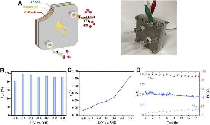
To evaluate the potential of the 2.9%Sn–Cu–O catalyst for practical applications, we integrated it into a 6.25 cm−2 membrane electrode assemble system. In this system, an anion exchange membrane (AEM) was sandwiched between the 2.9%Sn–Cu–O–GDE cathode and IrO2 anode to separate the chambers (Fig. 5A). The humidified CO2 gas was supplied to the cathode side with no catholyte and the anode side was circulated with 0.1 M KHCO3 anolyte. Fig. 5B shows potential-dependent FECO in the potential range of −2.8 to −4.0 V without iR compensation. The current–voltage response in the potential range of −2.8 to −4.0 V was recorded without iR compensation and is shown in Fig. 5C. The current increased with increasing voltage and a high eCO2RR current of −1.3 A was achieved at −4.0 V. The FECO increased concurrently, reaching the highest selectivity at −3.2 V with ∼96.2% FECO. A high plateau of CO FEs about 90% was maintained across the potential range of −2.8 to −4.0 V (Fig. 5D). We finally assessed the stability of the 2.9%Sn–Cu–O electrode in an MEA system by potentiostatic electrolysis at a cell voltage of −3.8 V. It exhibited a steady eCO2RR current of about 0.8 A, along with continuous CO production with about 90% FE, throughout the 15 h electrolysis process.Conclusions
In summary, the Sn-modified Cu catalyst with stable Cuδ+ sites has been successfully prepared and applied for CO2 electroreduction. 2.9%Sn–Cu–O exhibited a high FECO over a wide potential range from −0.35 V to −1.0 V with remarkable stability. The outstanding performance originated from the modified electronic structure and the appropriate oxidation states of Cu. A detailed study suggested that Cuδ+ with a low valence state could regulate the binding energy of intermediates to give high CO selectivity. The modifier element Sn could maintain the stability of Cuδ+ sites during electrolysis, resulting in high reactivity and selectivity for CO production. The optimized catalyst was also applied in an MEA for large-scale production of CO with very high efficiency. This work presents a promising electrocatalyst for CO production approaching practical expectations. We believe that it may also inspire the design of new catalytic systems for other reaction pathways.Data availability
All experimental data is available in the ESI.†Author contributions
X. X. T. performed all the experiments. W. W. G., S. J. L., S.·H. J., L. X., J. Q. F, X. P.·Y., C.·C. J., and Q. G. Z. performed the analysis of experimental data. X. F. S. and B. X. H. co-supervised the whole project. All authors discussed the results and commented on the manuscript.Conflicts of interest
The authors declare no competing financial interests.Acknowledgements
The work was supported by the National Natural Science Foundation of China (22002172 and 22121002), Beijing Natural Science Foundation (J210020) and Photon Science Center for Carbon Neutrality. The authors wish to thank X-ray absorption spectroscopy facility support of Beamline 4B9A at the Beijing Synchrotron Radiation Facility (BSRF). The X-ray emission spectroscopy beam time was granted by Beamline 4W1B of BSRF, Institute of High Energy Physics, Chinese Academy of Sciences. The staff members of 4W1B are acknowledged for their support in measurements and data reduction.Notes and references
- Y. Y. Birdja, E. Pérez-Gallent, M. C. Figueiredo, A. J. Göttle, F. Calle-Vallejo and M. T. M. Koper, Nat. Energy, 2019, 4, 732–745 CrossRef CAS.
- Z. Yan, J. L. Hitt, Z. Zeng, M. A. Hickner and T. E. Mallouk, Nat. Chem., 2021, 13, 33–40 CrossRef CAS PubMed.
- P. Saha, S. Amanullah and A. Dey, Acc. Chem. Res., 2022, 55, 134–144 CrossRef CAS PubMed.
- P. Zhu and H. Wang, Nat. Catal., 2021, 4, 943–951 CrossRef CAS.
- G. Wang, J. Chen, Y. Ding, P. Cai, L. Yi, Y. Li, C. Tu, Y. Hou, Z. Wen and L. Dai, Chem. Soc. Rev., 2021, 50, 4993–5061 RSC.
- R. Chen, H. Y. Su, D. Liu, R. Huang, X. Meng, X. Cui, Z. Q. Tian, D. H. Zhang and D. Deng, Angew. Chem., Int. Ed., 2020, 59, 154–160 CrossRef CAS.
- Y. Liu, D. Deng and X. Bao, Chem, 2020, 6, 2497–2514 CAS.
- D. U. Nielsen, X.-M. Hu, K. Daasbjerg and T. Skrydstrup, Nat. Catal., 2018, 1, 244–254 CrossRef CAS.
- S. Jin, Z. Hao, K. Zhang, Z. Yan and J. Chen, Angew. Chem., Int. Ed., 2021, 60, 20627–20648 CrossRef CAS PubMed.
- W. Ma, X. He, W. Wang, S. Xie, Q. Zhang and Y. Wang, Chem. Soc. Rev., 2021, 50, 12897–12914 RSC.
- W. Guo, X. Tan, J. Bi, L. Xu, D. Yang, C. Chen, Q. Zhu, J. Ma, A. Tayal, J. Ma, Y. Huang, X. Sun, S. Liu and B. Han, J. Am. Chem. Soc., 2021, 143, 6877–6885 CrossRef CAS PubMed.
- E. W. Lees, B. A. W. Mowbray, F. G. L. Parlane and C. P. Berlinguette, Nat. Rev. Mater., 2021, 7, 55–64 CrossRef.
- Z. Zhang, G. Wen, D. Luo, B. Ren, Y. Zhu, R. Gao, H. Dou, G. Sun, M. Feng, Z. Bai, A. Yu and Z. Chen, J. Am. Chem. Soc., 2021, 143, 6855–6864 CrossRef CAS PubMed.
- Y. Yang, M. Z. Ertem and L. Duan, Chem. Sci., 2021, 12, 4779–4788 RSC.
- B. A. Rosen, A. Salehi-Khojin, M. R. Thorson, W. Zhu, D. T. Whipple, P. J. A. Kenis and R. I. Masel, Science, 2011, 334, 643–644 CrossRef CAS PubMed.
- J. Chen, Z. Li, X. Wang, X. Sang, S. Zheng, S. Liu, B. Yang, Q. Zhang, L. Lei, L. Dai and Y. Hou, Angew. Chem., Int. Ed., 2022, 134, e202111683 Search PubMed.
- S. B. Varandili, D. Stoian, J. Vavra, K. Rossi, J. R. Pankhurst, Y. T. Guntern, N. Lopez and R. Buonsanti, Chem. Sci., 2021, 12, 14484–14493 RSC.
- Z. Sun, Y. Hu, D. Zhou, M. Sun, S. Wang and W. Chen, ACS Energy Lett., 2021, 6, 3992–4022 CrossRef CAS.
- Y. Zhou, F. Che, M. Liu, C. Zou, Z. Liang, P. De Luna, H. Yuan, J. Li, Z. Wang, H. Xie, H. Li, P. Chen, E. Bladt, R. Quintero-Bermudez, T.-K. Sham, S. Bals, J. Hofkens, D. Sinton, G. Chen and E. H. Sargent, Nat. Chem., 2018, 10, 974–980 CrossRef CAS PubMed.
- H. Wu, J. Li, K. Qi, Y. Zhang, E. Petit, W. Wang, V. Flaud, N. Onofrio, B. Rebiere, L. Huang, C. Salameh, L. Lajaunie, P. Miele and D. Voiry, Nat. Commun., 2021, 12, 7210 CrossRef CAS.
- J. Wang, H. Y. Tan, Y. Zhu, H. Chu and H. M. Chen, Angew. Chem., Int. Ed., 2021, 60, 17254–17267 CrossRef CAS PubMed.
- W. Ma, S. Xie, T. Liu, Q. Fan, J. Ye, F. Sun, Z. Jiang, Q. Zhang, J. Cheng and Y. Wang, Nat. Catal., 2020, 3, 478–487 CrossRef CAS.
- H. Xu, D. Rebollar, H. He, L. Chong, Y. Liu, C. Liu, C.-J. Sun, T. Li, J. V. Muntean, R. E. Winans, D.-J. Liu and T. Xu, Nat. Energy, 2020, 5, 623–632 CrossRef CAS.
- H. Shang, D. Kim, S. K. Wallentine, M. Kim, D. M. Hofmann, R. Dasgupta, C. J. Murphy, A. Asthagiri and L. R. Baker, Chem. Sci., 2021, 12, 9146–9152 RSC.
- L. Xiong, X. Zhang, H. Yuan, J. Wang, X. Yuan, Y. Lian, H. Jin, H. Sun, Z. Deng, D. Wang, J. Hu, H. Hu, J. Choi, J. Li, Y. Chen, J. Zhong, J. Guo, M. H. Rummerli, L. Xu and Y. Peng, Angew. Chem., Int. Ed., 2021, 60, 2508–2518 CrossRef CAS PubMed.
- T. Zheng, C. Liu, C. Guo, M. Zhang, X. Li, Q. Jiang, W. Xue, H. Li, A. Li, C. W. Pao, J. Xiao, C. Xia and J. Zeng, Nat. Nanotechnol., 2021, 16, 1386–1393 CrossRef CAS PubMed.
- F. Franco, C. Rettenmaier, H. S. Jeon and B. Roldan Cuenya, Chem. Soc. Rev., 2020, 49, 6884–6946 RSC.
- D. Yang, Q. Zhu, X. Sun, C. Chen, W. Guo, G. Yang and B. Han, Angew. Chem., Int. Ed., 2020, 59, 2354–2359 CrossRef CAS PubMed.
- D. D. Zhu, J. L. Liu and S. Z. Qiao, Adv. Mater., 2016, 28, 3423–3452 CrossRef CAS.
- J. Gu, F. Héroguel, J. Luterbacher and X. Hu, Angew. Chem., Int. Ed., 2018, 57, 2943–2947 CrossRef CAS.
- F. Cheng, X. Zhang, K. Mu, X. Ma, M. Jiao, Z. Wang, P. Limpachanangkul, B. Chalermsinsuwan, Y. Gao, Y. Li, Z. Chen and L. Liu, Energy Technol., 2020, 9, 2000799 CrossRef.
- T. N. Nguyen and C. T. Dinh, Chem. Soc. Rev., 2020, 49, 7488–7504 RSC.
- K. Ye, Z. Zhou, J. Shao, L. Lin, D. Gao, N. Ta, R. Si, G. Wang and X. Bao, Angew. Chem., Int. Ed., 2020, 59, 4814–4821 CrossRef CAS PubMed.
- Z. Z. Niu, F. Y. Gao, X. L. Zhang, P. P. Yang, R. Liu, L. P. Chi, Z. Z. Wu, S. Qin, X. Yu and M. R. Gao, J. Am. Chem. Soc., 2021, 143, 8011–8021 CrossRef CAS.
- G. Wen, B. Ren, M. G. Park, J. Yang, H. Dou, Z. Zhang, Y. P. Deng, Z. Bai, L. Yang, J. Gostick, G. A. Botton, Y. Hu and Z. Chen, Angew. Chem., Int. Ed., 2020, 59, 12860–12867 CrossRef CAS PubMed.
- D. Tahir and S. Tougaard, J. Phys.: Condens. Matter, 2012, 24, 175002 CrossRef PubMed.
- N. Pauly, S. Tougaard and F. Yubero, Surf. Sci., 2014, 630, 294–299 CrossRef CAS.
- S. R. B. a. D. D. Sarma, J. Phys.: Condens. Matter, 1992, 4, 7607–7616 CrossRef.
- A. D. Handoko, F. Wei, Jenndy, B. S. Yeo and Z. W. Seh, Nat. Catal., 2018, 1, 922–934 CrossRef CAS.
Footnote |
| † Electronic supplementary information (ESI) available. See https://doi.org/10.1039/d2sc04607e |
| This journal is © The Royal Society of Chemistry 2022 |

