 Open Access Article
Incorporating fluorescent nanomaterials in organically modified sol–gel materials – creating single composite optical pH sensors†
Dávid
Bartoš
,
Morten
Rewers
 ,
Lu
Wang
* and
Thomas Just
Sørensen
 *
*
Nano-Science Center & Department of Chemistry, University of Copenhagen, Universitetsparken 5, 2100 Copenhagen Ø, Denmark. E-mail: luwa@chem.ku.dk; tjs@chem.ku.dk
First published on 8th November 2021
Abstract
Optical sensors hold the promise of providing the coupling between the tangible and the digital world that we are currently experiencing. The core of optical sensor development lies in materials development, where specific requirements of opposing physicochemical properties create a significant obstacle. The sensor material must provide dye retention, while ensuring porosity for analyte transport. The sensor material must provide hydrophobic pockets for dyes to ensure high signal intensity, while remaining fully hydrophilic to measure in water. We have previously reported optical sensors, where we compromised on sensor manufacturing by using a double-layer composite. Here, we report a composite organically modified sol–gel (ORMOSIL) polymer, where polystyrene (PS) nanoparticles (NPs) have been incorporated. This allows all the opposing requirements on optical sensor materials to be fulfilled, and by introducing a hydrophobic reference dye in the fully hydrophobic compartments of the sensor material. We show that we can incorporate any hydrophobic fluorophore in this material, even those which are suffering from quenching in water. In this work, PS NPs with 1,13-dimethoxyquinacridinium (DMQA) were immobilized in a composite sol–gel material with pH responsive diazaoxatriangulenium (DAOTA) dyes prior to curing. The multicomponent sensor composite was cured on a polycarbonate hemiwicking substrate, and the resulting fluorescence intensity ratiometric optical pH sensor was shown to have excellent performance. We expect that this type of composite sensor materials will allow the creation of next generation industrial chemosensors.
Introduction
The concept of optical pH sensors has been known since pH was defined by Sørensen.1,2 Even so, disregarding colorimetric pH indicators, commercial pH sensors are mainly potentiometric pH meters that provide a linear electromotive force (EMF) response to pH obeying the Nernst equation.2–6 There are clear advantages of optical sensors,7–12 but complications regarding calibration: optical pH sensors report optical signals fitting to a sigmoidal curve where the response range depends on the pKa of the pH-sensitive dye,13,14 and a limited stability of the sensor material have reduced their industrial applicability.15–17 We have recently reported a new sensor material for optical sensors,18 and the first high performance pH sensor using this matrix.3 One unresolved issue with this sensor design is the reference dyes or lipophilic sensor dyes cannot be incorporated into the matrix, without compromising performance.19 Here, we have solved this problem, by adding an additional component to the composite sensor material.The first generation of fiber-based optical sensors emerged around 1980.20,21 In the following years, absorption or fluorescent-based pH indicators were incorporated in polymers, such as polystyrene,22 polyacrylamide,23,24 poly(methyl methacrylate) (PMMA),25,26 and deposited on the fiber tip. Because of the high sensitivity, fluorescence sensors have been more extensively studied than other types of colorimetric sensors.23,24,27,28 And most of commercially available chemical optical sensors are based on fluorescence, in particular fluorescence lifetime measured in the frequency domain.29–32 However, and despite the success of optical oxygen sensors,33–36 optical chemosensors are still not prevalent on the market.6 The challenges that remain are to improve the stability and response time of the sensor. The main problems are i) dye leakage, ii) fluorescence quenching, iii) photobleaching, and iv) slow diffusion speed of the analytes into the sensor material. There has been a strong focus on studying new matrices for sensor materials,37–39 and on discovering improved methods for immobilizing the sensing components.21,40 We have described an organically modified silicon sol–gel that solves many of these issues, when it comes to creating a competitive optical pH sensor.3,18,41–43 The resulting sensor material has good chemical, photochemical and thermal stability as well as fast diffusion of H+, while excluding all other ions. The sensor material has the capacity to fully encapsulate the pH responsive dye, the ability to firmly stick to polymer and glass substrate, a long shelf-life and is fully biocompatible. In all points relating to the response of the pH sensor the behavior this material is close to ideal. However, the newly designed sensor, based on a ratiometric response in fluorescence intensity, has an issue incorporating – typically lipophilic – reference dye in this highly hydrophilic sensor material.
In the ideal sensor, the reference dye – a photostable fluorescent dye that is inert to pH – must be an integral part of the sensor material. The role of the reference dye is to compensate for changes in the optical system, analogues in concept to the reference electrode of a conventional pH meter. Quantum dots (QDs) have been used as reference dyes due to good light stability and high quantum yield,50–52 but as there remains issues with biocompatibility we prefer molecular fluorophores. We have reported optical pH sensors with an intensity ratiometric response, where different dyes have been incorporated as part of the sensor material.42 All the reference dyes shown in Fig. 1 suffer from unspecific quenching of the reference dye by water,53 even when the highly photostable terrylene based dye (TDI) is incorporated in the most hydrophobic of the ORMOSIL matrices.19,54 The current solution is to make an optode where the reference dye is kept in a dry environment, by depositing it in polystyrene on the back of the substrate.3 This optode configuration is not ideal for industrial production, and the temperature stability of polystyrene limits the application areas of the resulting optical pH sensor.
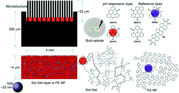 | ||
| Fig. 1 Representation of the elements in the composite materials used in an optical pH sensor illustrating the scale of the different elements. Left, polycarbonate substrate and microstructure with sensor material shown to scale, with the sol–gel layer magnified to show the relative scale of the polystyrene nanoparticles. Right, pH responsive azadioxatriangulenium (ADOTA) and diazaoxatriangulenium (DAOTA) dyes,44,45 and lipophilic reference benzo- and carbon-bridged diazatriangulenium (BDATA and CDATA),46,47 terrylenediimide (TDI),48 and 1,13-dimethoxyquinacridinium (DMQA) dyes.49 The local environment of pH responsive and reference dyes in sol–gel and polystyrene nanoparticle is illustrated. | ||
Here, we present a new composite sensor material to alleviate the issues we have seen with the reference dye. We suggest to incorporate the reference dye in polystyrene nanoparticles (PS NPs) into the ORMOSIL prior to curing, thereby creating hydrophobic polystyrene compartments in the ORMOSIL network. This design segregates the reference dye from the water contacting material and we obtain a constant fluorescence signal from the reference dye. PS NPs were buried in ORMOSIL with a high temperature stability and the integrated sensor material tolerates higher temperatures. The design simplifies production as the optode – the active element in the optical sensor – is created by deposition of a solution directly on the substrate. The design concept is illustrated in Fig. 1. A concern is the distribution of nanoparticles is not homogeneous, but as we probe an area measured in millimeters, we aim to prove that any variation in the stochastic distribution of the nanoparticles in the sol–gel will be vanishing, and that an average fluorescence intensity per volume will be observed.55
Optical pH sensors based on nano/microparticles in the gel matrix have been reported previously. The dyes were encapsulated with plasticizers or surfactants and form lipophilic particles, then they were embedded in hydrogels and polymers such as polyvinyl alcohol (PVA),56 polyacrylamide,57 and agarose.58 The main difference to our work reported here, is that they mainly focus on hydrogel-based sensor materials that are not stable in industrial applications. The approach based on organically modified silicate materials are more robust,18 and we hope to be able to use the sensor material reported here to incorporate not only molecular dyes, but also more complex fluorescent materials.55,59–61
Methods and materials
Reagents
4-(2-Hydroxyethyl)-1-piperazineethanesulfonic acid (HEPES), sodium hydroxide (NaOH), hydrochloric acid (HCl), toluene, dichloromethane (CH2Cl2), ethanol, sodium dodecyl sulfate (SDS), 3-(glycidoxy)propyltrimethoxysilane (GPTMS; >98%), and polystyrene (PS; Lot.: 07430MO-404), borontrifluoride diethyletherate (BF3O(CH2CH3)2) were obtained from Sigma-Aldrich. Propyl triethoxysilane (PrTES; 97%) was purchased from Alfa Aesar. The pH-responsive dye N-(2-hydroxy-5-(trifluoromethyl)phenyl)-N′-(dodecyl)-diazaoxatriangulenium hexafluorophosphate, (DAOTA) and the reference dye N,N′-(2-ethylhexyl)-1,13-dimethoxyquinacridinium hexafluorophosphate (DMQA) were synthesized as previously reported.62,63 Polycarbonate substrate (4 mmØ)54 was obtained from NIL Technology, Denmark. All salts and solvents used were analytical grade or higher. All testing solutions were prepared by dissolving appropriate salts into deionized water (Milli-Q).Instrumentation and measurements
Emulsification was done with the sonicator (XS-sonic, FS-300N). Centrifugation was done by the centrifuge (MiniSpin® plus, Eppendorf) with disposable Eppendorf tubes (1.5 ml). The fluorescence spectra for the DMQA-doped NP were recorded using a Cary Eclipse fluorescence spectrophotometer (Agilent Technologies). Scanning electron microscopic (SEM) images were obtained under Jeol 7800F-Prime scanning electron microscope (10 kV). The PS NP solution was deposited on the cleaned polished side of the silicon wafers and left them dry before the measurements. For the SEM images of the sol–gel containing PS NPs, the sol–gel material was spin-coated (20 μL, 3000 rpm, for 30 s) onto a silicon wafer which was subsequently cured at 110 °C for 3 hours before the measurements. Images and fluorescence spectra of one spot were obtained by a wide-fields microscope (ZEISS, filter: 475/40ex, 510+em). Fluorescence intensity distribution of the sensor spots were also evaluated by the microplate reader (BMG LABTECH, PHERAstar FSX) with sensor spots glued on the GREINER 96 F-BOTTOM microplate (filter, FP 540-20/590-20 for DAOTA and HTRF 337/665-620 for DMQA; matrix scan 20 × 20, 4 mmØ).A home-built hardware platform containing an LED light source and spectrometer was used to measure the fluorescence response of the pH optical sensor.54 The spectrometer acquired spectra with background light subtraction for each measurement. The readout spectra were average of 3 continuous signal capture with an integration time of 500 ms for each.
Preparation of the optode
![[thin space (1/6-em)]](https://www.rsc.org/images/entities/char_2009.gif) :
:![[thin space (1/6-em)]](https://www.rsc.org/images/entities/char_2009.gif) 1). 2.4 mg of the reference dye (DMQA) was dissolved herein. 14 mg of SDS was dissolved in 14 ml of Milli-Q water by stirring for 30 min at room temperature. The two solutions were mixed and the two-phase system was sonicated with the probe (8 mmØ, sonicating power: 60 W) with 1 second on and 1 second off timing for a total duration of 60 seconds while stirring at 300 rpm. This process was repeated 5 times with a waiting time of 60 minutes between each sonication during which the vial is left stirring at 300 rpm with a closed cap. After the fifth sonication, the sample is left with an open cap on and stirring at 300 rpm for 48 hours to evaporate all the toluene. The obtained milky solution was centrifuged (13
1). 2.4 mg of the reference dye (DMQA) was dissolved herein. 14 mg of SDS was dissolved in 14 ml of Milli-Q water by stirring for 30 min at room temperature. The two solutions were mixed and the two-phase system was sonicated with the probe (8 mmØ, sonicating power: 60 W) with 1 second on and 1 second off timing for a total duration of 60 seconds while stirring at 300 rpm. This process was repeated 5 times with a waiting time of 60 minutes between each sonication during which the vial is left stirring at 300 rpm with a closed cap. After the fifth sonication, the sample is left with an open cap on and stirring at 300 rpm for 48 hours to evaporate all the toluene. The obtained milky solution was centrifuged (13![[thin space (1/6-em)]](https://www.rsc.org/images/entities/char_2009.gif) 000 rpm, 5 min), washed with ethanol/water (v/v, 1
000 rpm, 5 min), washed with ethanol/water (v/v, 1![[thin space (1/6-em)]](https://www.rsc.org/images/entities/char_2009.gif) :
:![[thin space (1/6-em)]](https://www.rsc.org/images/entities/char_2009.gif) 3), and then centrifugation. The obtained centrifugate was dried in the oven at 35 °C.
3), and then centrifugation. The obtained centrifugate was dried in the oven at 35 °C.
a) Procedure for preparation of PrTES-gel component: 1.25 ml PrTES was dissolved in 2 ml absolute ethanol while stirring. Thereafter, 0.4 ml of 0.1 M HCl solution was added dropwise. This mixture was left stirring for 7 days.
b) Procedure for preparation of GPTMS-gel component: 2.4 mg pH-responsive dye was dissolved in 5.5 ml of absolute ethanol. 3 ml of GPTMS (27 mmol) was added while stirring. Then 0.4 ml of cold BF3O(CH2CH3)2 was added dropwise. The mixture was stirred for 30 min then 1 ml of Milli-Q water was added to the solution. The resulting mixture was stirred for 4 h.
c) Combination of the two sol–gels: when the two gel components have been prepared they were combined in (PrTES![[thin space (1/6-em)]](https://www.rsc.org/images/entities/char_2009.gif) :
:![[thin space (1/6-em)]](https://www.rsc.org/images/entities/char_2009.gif) GPTMS) volume ratio of 3
GPTMS) volume ratio of 3![[thin space (1/6-em)]](https://www.rsc.org/images/entities/char_2009.gif) :
:![[thin space (1/6-em)]](https://www.rsc.org/images/entities/char_2009.gif) 7 and left agitated for one day.
7 and left agitated for one day.
d) Combination of the PS particles with the sol–gel: 6 mg of the reference dye-doped PS nanoparticles were added into 0.5 ml of aged sol–gel. The resulting sol–gel was sonicated in an ultrasonic bath for 1 minute to properly disperse the nanoparticles.
Results and discussion
Sensor material synthesis
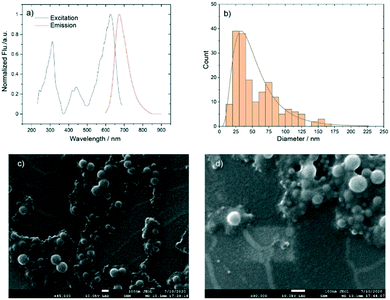
The reference dye N,N′-(2-ethylhexyl)-1,13-dimethoxyquinacridinium (DMQA),49,65–67 see Fig. S1,† belongs to the class of highly photostable triangulenium fluorophores (λem = 660 nm).44,45,68 The dye has no response to pH, but it suffers from fluorescence quenching when exposed to water.66 Furthermore, we have observed that, in the ORMOSIL sol–gel sensor material, DMQA is not chemically stable.42 To avoid quenching and increase the chemical stability DMQA-doped polystyrene nanoparticles were synthesized by the reproducible and scalable emulsification method developed in-house.64 Briefly, sodium dodecyl sulfate (SDS) was used as a stabilizing agent for the DMQA/polystyrene/toluene droplets formed upon emulsification of a water/toluene mixture. The toluene was removed from the system by slow evaporation over 48 h with continued stirring. The extra surfactant was then removed by washing with ethanol/water (v/v, 1![[thin space (1/6-em)]](https://www.rsc.org/images/entities/char_2009.gif) :
:![[thin space (1/6-em)]](https://www.rsc.org/images/entities/char_2009.gif) 3) and the purified DMQA-doped PS NPs were obtained after the evaporation of the remaining solvent. Fig. 2 shows the fluorescence excitation and emission spectra, the size distribution and selected SEM images of the DMQA-doped PS NPs.
3) and the purified DMQA-doped PS NPs were obtained after the evaporation of the remaining solvent. Fig. 2 shows the fluorescence excitation and emission spectra, the size distribution and selected SEM images of the DMQA-doped PS NPs.
The triangulenium based pH-sensitive DAOTA dyes,13,69 and the sol–gel synthesis of the sensor material is reported in our previous work.3,18,43 Previous work reports on sensors with dyes that have a triethoxysilane group in their structure, which covalently bind the dye to the silicate network of the ORMOSIL. Here, we use a pH-responsive DAOTA dye (Fig. S1†) that physisorbs in the ORMOSIL material. The performance of the physisorption approach is similar to that of the chemisorption for these dyes.19 To make the new sensor material, an aliquot of DMQA-doped PS NPs were mixed with matured sol–gel containing DAOTA. This mixture was then deposited onto a 4 mmØ micro-structured polycarbonate substrate.70 After curing (110 °C, 3 h) and conditioning in HEPES buffer (20 mM, 1 h), the new pH sensor spot was ready to use. The details of the full procedure can be found in the Methods and materials.
More than ten optodes were made. First, we investigated the structure of the resulting sensor material on the micro- and nanoscales. Then, we evaluate the distribution of the DMQA-doped PS NPs to ensure that the nanoparticles provide a uniform signal across the 4 mmØ spot. And finally we investigated the performance of the resulting optical pH sensor.4
Structure of new sensor material
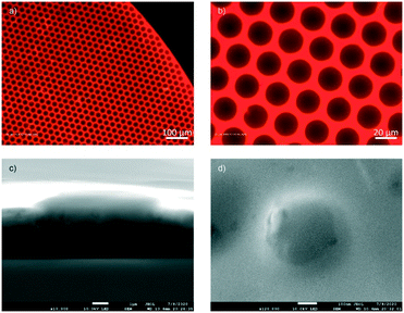
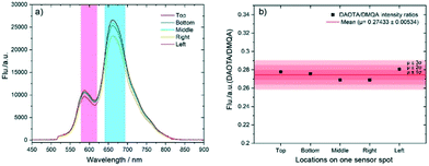
First, a visual inspection was performed to see if the homogeneous intensity could be observed across the 4 mmØ spots using an epifluorescence wide-field microscope equipped with filter sets matching the DAOTA and DMQA emissions. Images of a single sensor spot are shown under different magnifications in Fig. 3a and b. The images capture emission signals from both the DMQA inside the PS NPs and the DAOTA embedded in the sol–gel. The red color shows the fluorescence intensity of both dyes and we see that the intensity is distributed evenly across the microstructure.To further probe the structure of the sensor material, SEM images were recorded. Fig. 3c and d show the clear spherical edge of the NPs, which proves that the NPs do not dissolve in the sol–gel and remain intact in the curing process. As expected, the nanoparticles do not disperse evenly in the sensor gel on the nanoscale (Fig. 3c and S2†). But as all applications measure on the macroscopic scale, where the integrated optical signal is recovered from a mm2 area rather than from individual point on the nanoscale, we do not expect this to be an issue. For instance, the optical fiber on our hardware probes an area exceeding 1 mmØ. To prove this point, two experiments were performed. First, five different locations on a single optical sensor spot were measured to evaluate the uniformity of the sensor with 20× magnification (Fig. 4, see illustration in Fig. S3†). To produce the readout from the sensor spot, each spectrum was integrated from 580 to 620 nm for DAOTA and 640 to 695 nm for DMQA, and the ratios of integrated intensities of these two peak areas were plotted in Fig. 4b corresponding to the positions of the data acquisition (top, bottom, middle, right or left on the spot). The small deviation indicates the sensor material has a uniform NP distribution. To quantify this result, we investigated ten sensor spots in a fluorescence plate reader. In this experiment, 100 points across each sensor spot were investigated, and we found that the variation in DAOTA/DMQA fluorescence intensity ratio was lower than 5% (Table 1, see data treatment progress in Fig. S4†), fully consistent with the 2% estimated from the microscopy measurements. We thus conclude that the fluorescence signal is homogeneous on the scale of millimeters, therefore not impacting the area probed by the optical fiber.
| Sensor spot | 1 | 2 | 3 | 4 | 5 | 6 | 7 | 8 | 9 | 10 |
|---|---|---|---|---|---|---|---|---|---|---|
| Average sensor signal of 100 points | 1.48 | 1.66 | 1.27 | 0.65 | 0.59 | 0.91 | 1.60 | 1.12 | 0.99 | 0.94 |
| Standard deviation | 0.07 | 0.04 | 0.03 | 0.03 | 0.03 | 0.04 | 0.04 | 0.04 | 0.02 | 0.02 |
| Variation | 5% | 2% | 3% | 5% | 5% | 4% | 3% | 4% | 2% | 2% |
Performance of new optical sensor
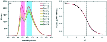
pH response was tested in HEPES buffer solution (20 mM) by the home-built fluorescence microscope set-up (Fig. S5†).54Fig. 5 shows the fluorescence emission spectra at different pH adjusted by pumping HCl (1 M) or NaOH (1 M). Each spectrum is the mean value of 3 spectra obtained after fluorescence intensity reached equilibrium for every pH adjustment (Fig. 5). Both of the emission bands (DAOTA, 595 nm; DMQA, 660 nm) decrease with the decreasing of pH value. However, the decrease of the band at 660 nm is due to the overlap with the peak 595 nm, as it has been confirmed DMQA has no fluorescence response to pH when it is in the gel phase.41 The normalized and smoothed fluorescence spectra were shown in Fig. S6,† and the pH is evaluated by the ratiometric signal of the integrated peak areas (DAOTA/DMQA).By monitoring the sensors response to pH, we could see the responses are reversible and repeatable (Fig. S7†). Fig. 5b shows the sigmoidal calibration curve fitted to the pH response data from Fig. 5a. pKa of this pH-responsive dye is 6.33 ± 0.05 consistent with the pKa value 6.5 from previous reports based on the same dye.62 This indicated the sensor material with and without nanoparticles have similar photophysical properties. The slight difference of pKa values observed between here and our reported studies13,54 may just as well be due to the structural difference between physisorped and chemisorbed dyes.
The response time of a pH sensor depends on the rate of diffusion of proton.4,43 The main factors governing these rates are the nature of the sol–gel and the thickness of the sol–gel layer. For a specific sensor, response time is also related to the measurement procedure such as the direction and the range of the pH change. Response time here was calculated based on two exponential decay functions.54Fig. 6 shows t90 is 35 s for the pH change from 9.09 to 3.71 and 150 s for 3.72 to 9.09. The response is slower for the change from acid to base because the sol–gel selectively allows for proton transport.18 In our previous report, t90 of such sol–gel based optical pH sensor is 19 s for the pH change from 8 to 3, and 51 s for 3 to 8. We hypothesize that the cause of the slower response here is that the proton transporting PEG-like networks are impeded by the PS NPs or some aggregated NPs in the sol–gel.
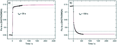 | ||
| Fig. 6 Time response of the optical sensor spot with pH change from a) 9.09 to 3.71 and b) 3.72 to 9.09 (data was captured every 10 s). | ||
Stability was tested by a long-term continually fluorescence intensity measurement which lasted 21 hours in HEPES (20 mM, r.t., in the dark and around 4400 measurements). pH response was tested before and after the long-term measurement. Fig. 7a shows the integrated values for both dyes were stable during the long-term measurement, and so was the ratio signal of the two dyes (Fig. 7b). The drift of the sensor signal is calculated to be 1.55 × 10⁻³/h. The positive drift due to the degradation of DMQA exceeds that of the pH responsive dye.71 It should be noted that extensive leakage studies was done for the DMQA and DAOTA containing sol–gel in preparation of our previous report.18 No dye leaching was detected from cured and washed sensors, sensors that had undergone physical stress (cutting with scissors) showed leaching in the form of sol–gel flakes, no leaching of dyes could be detected, and no loss of sol–gel was seen in intact sensors.
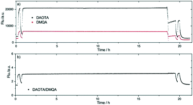 | ||
| Fig. 7 Stability testing for one pH optical sensor spot. The integrated fluorescence intensity for a) both dyes and b) their ratio plotted versus time (data was captured every 18 s). | ||
The trace in Fig. 7 shows a kink at 18.5 h, where the level of buffer solution due to evaporation dropped below the fiber tip. From this point, interface reflection weakened the fluorescence signal. Fig. 7a shows that both DAOTA and DMQA signals changed significantly, but Fig. 7b shows that the sensor signal did not vary although an increase in the noise is evident.
Overall this proof-of-concept optical pH sensor exhibits acceptable response time and shows active range at pH 6.33 ± 1.5. High stability, reproducible sensor spots indicates that this novel composite material is a promising candidate for developing optical sensors for industrial applications.
Conclusions
After ten years of research, we are able to present a sensor material for optical chemosensors that has hydrophilic areas that allow for fast analyte transport and hydrophobic areas able to host water sensitive dyes. By doping the hydrophobic dyes into the polystyrene nanoparticles that can be produced reproducibly and in bulk, we successfully prepared an optical pH sensor where the reference dye is protected from water-quenching. The work reported here shows that we are able to produce optical chemosensors in a single deposition. We have developed a composite sensor material that is both hydrophilic and hydrophobic, and that maintains all the beneficial properties of the parent ORMOSIL composite.SEM images proved that the polystyrene nanoparticles are incorporated intact into the sensor material, and we were able to prove that the nanoparticles are evenly distributed in the sensor material at this measurement scale. We prepared pH optodes using the new sensor materials, and proved that we can move from separated, two-layer optode,3 to a single layer optode where both reference and pH responsive dyes is integrated into the sensor material, while maintaining the properties of the original optical pH sensor.
Several pH sensors were prepared. They showed no obvious dye leakage, were found to maintain a fast and reliable response, and we found that the pH optical sensor was stable for more than 5000 measurements. The polycarbonate matrix limits the temperature stability of our current sensor. The next step will be to update the matrix material and build a dedicated hardware, and incorporate the new sensor material in an industrial sensor.
Author contributions
T. J. S. conceived the study. D. B., L. W. and M. R. prepared and tested the pH sensors. L. W. and T. J. S. interpreted the data and wrote the manuscript. All authors have given approval to the final version of the manuscript.Conflicts of interest
There are no conflicts to declare.Acknowledgements
The authors thank Novo Nordisk Fonden (grant #NNF19OC0057136), Villum Fonden (grant #14922), Carlsbergfondet and the University of Copenhagen for support. Laura Grenier is thanked for her input to the final manuscript.Notes and references
- S. P. L. Sørensen, Biochem. Z., 1909, 21, 131–304 Search PubMed.
- A. Steinegger, O. S. Wolfbeis and S. M. Borisov, Chem. Rev., 2020, 120, 12357–12489 CrossRef CAS PubMed.
- C. G. Frankær, K. J. Hussain, T. C. Dorge and T. J. Sorensen, ACS Sens., 2019, 4, 26–31 CrossRef PubMed.
- C. G. Frankær and T. J. Sørensen, Analyst, 2019, 144, 2208–2225 RSC.
- S. M. Borisov and O. S. Wolfbeis, Chem. Rev., 2008, 108, 423–461 CrossRef CAS PubMed.
- O. S. Wolfbeis, Angew. Chem., 2013, 52, 9864–9865 CrossRef CAS PubMed.
- C. Card, K. Clark and J. Furey, BioProcess Int., 2011, 9, 36–42 Search PubMed.
- H. Weichert, J. Lüders, M. Becker, T. Adams and J. Weyand, BioProcess Int., 2014, 12, 20–24 Search PubMed.
- N. H. Janzen, M. Schmidt, C. Krause and D. Weuster-Botz, Bioprocess Biosyst. Eng., 2015, 38, 1685–1692 CrossRef CAS PubMed.
- D. Wencel, T. Abel and C. McDonagh, Anal. Chem., 2014, 86, 15–29 CrossRef CAS PubMed.
- J. Newton, R. Oeggl, N. H. Janzen, S. Abad and D. Reinisch, Eng. Life Sci., 2020, 20, 331–337 CrossRef CAS PubMed.
- D. Wu, A. C. Sedgwick, T. Gunnlaugsson, E. U. Akkaya, J. Yoon and T. D. James, Chem. Soc. Rev., 2017, 46, 7105–7123 RSC.
- C. G. Frankær, M. Rosenberg, M. Santella, K. J. Hussain, B. W. Laursen and T. J. Sørensen, ACS Sens., 2019, 4, 764–773 CrossRef PubMed.
- P. W. Dillingham, B. S. O. Alsaedi, S. Granados-Focil, A. Radu and C. M. McGraw, ACS Sens., 2020, 5, 250–257 CrossRef CAS PubMed.
- I. Dalfen, R. I. Dmitriev, G. Holst, I. Klimant and S. M. Borisov, Anal. Chem., 2018, 91, 808–816 CrossRef PubMed.
- B. M. Weidgans, C. Krause, I. Klimant and O. S. Wolfbeis, Analyst, 2004, 129, 645–650 RSC.
- M. Mosshammer, M. Strobl, M. Kuhl, I. Klimant, S. M. Borisov and K. Koren, ACS Sens., 2016, 1, 681–687 CrossRef CAS.
- C. G. Frankær, K. J. Hussain, M. Rosenberg, A. Jensen, B. W. Laursen and T. J. Sørensen, ACS Sens., 2018, 3, 692–699 CrossRef PubMed.
- T. Sørensen, M. Rosenberg and B. Laursen, International Pat., WO/2015/058778, 2015 Search PubMed.
- J. O. W. Norris, Analyst, 1989, 114, 1359–1372 RSC.
- J. Lin, TrAC, Trends Anal. Chem., 2000, 19, 541–552 CrossRef CAS.
- G. F. Kirkbright, R. Narayanaswamy and N. A. Welti, Analyst, 1984, 109, 1025–1028 RSC.
- W. Tan, Z. Shi, S. Smith, D. Birnbaum and R. Kopelman, Science, 1992, 258, 778–781 CrossRef CAS PubMed.
- W. Tan, Z. Shi and R. Kopelman, Anal. Chem., 1992, 64, 2985–2990 CrossRef CAS.
- C. Egami, K. Takeda, M. Isai and M. Ogita, Opt. Commun., 1996, 122, 122–126 CrossRef CAS.
- C. Egami, Y. Suzuki, O. Sugihara, H. Fujimura and N. Okamoto, Jpn. J. Appl. Phys., 1997, 36, 2902–2905 CrossRef CAS.
- M. Schäferling, Angew. Chem., Int. Ed., 2012, 51, 3532–3554 CrossRef PubMed.
- T. Ueno and T. Nagano, Nat. Methods, 2011, 8, 642–645 CrossRef CAS PubMed.
- M. P. Christiansen, L. J. Klaff, T. S. Bailey, R. Brazg, G. Carlson and K. S. Tweden, Diabetes Technol. Ther., 2019, 21, 231–237 CrossRef CAS PubMed.
- W. M. Shih, Z. Gryczynski, J. R. Lakowicz and J. A. Spudich, Cell, 2000, 102, 683–694 CrossRef CAS PubMed.
- PyroScience Sensor Tehcnology, https://www.pyroscience.com/en/, 11/11/2020 9:25.
- PreSens precision sensing, https://www.presens.de/products/ph, 11/11/2020 9:25.
- X. D. Wang and O. S. Wolfbeis, Chem. Soc. Rev., 2014, 43, 3666–3761 RSC.
- O. S. Wolfbeis, BioEssays, 2015, 37, 921–928 CrossRef CAS PubMed.
- O. S. Wolfbeis, J. Mater. Chem., 2005, 15, 2657–2669 RSC.
- C. McDonagh, C. S. Burke and B. D. MacCraith, Chem. Rev., 2008, 108, 400–422 CrossRef CAS PubMed.
- P. C. Jerónimo, A. N. Araújo and M. C. B. Montenegro, Talanta, 2007, 72, 13–27 CrossRef PubMed.
- E. Wang, K.-F. Chow, V. Kwan, T. Chin, C. Wong and A. Bocarsly, Anal. Chim. Acta, 2003, 495, 45–50 CrossRef CAS.
- S. T. Lee, J. Gin, V. Nampoori, C. Vallabhan, N. Unnikrishnan and P. Radhakrishnan, J. Opt. A: Pure Appl. Opt., 2001, 3, 355–359 CrossRef CAS.
- D. Wencel, T. Abel and C. McDonagh, Anal. Chem., 2014, 86, 15–29 CrossRef CAS PubMed.
- M. Rosenberg, B. W. Laursen, C. G. Frankær and T. J. Sørensen, Adv. Mater. Technol., 2018, 3, 1800205 CrossRef.
- T. J. Sørensen, M. Rosenberg, C. G. Frankær and B. W. Laursen, Adv. Mater. Technol., 2018, 0, 1800561 CrossRef.
- C. G. Frankær and T. J. Sørensen, ACS Omega, 2019, 4, 8381–8389 CrossRef PubMed.
- B. W. Laursen and F. C. Krebs, Angew. Chem., Int. Ed., 2000, 39, 3432–3434 CrossRef CAS PubMed.
- B. W. Laursen and F. C. Krebs, Chem. – Eur. J., 2001, 7, 1773–1783 CrossRef CAS.
- M. Rosenberg, K. R. Rostgaard, Z. Liao, A. Ø. Madsen, K. L. Martinez, T. Vosch and B. W. Laursen, Chem. Sci., 2018, 9, 3122–3130 RSC.
- M. Rosenberg, M. Santella, S. A. Bogh, A. V. Muñoz, H. O. B. Andersen, O. Hammerich, I. Bora, K. Lincke and B. W. Laursen, J. Org. Chem., 2019, 84, 2556–2567 CrossRef CAS PubMed.
- F. O. Holtrup, G. R. J. Müller, H. Quante, S. De Feyter, F. C. De Schryver and K. Müllen, Chem. – Eur. J., 1997, 3, 219–225 CrossRef CAS PubMed.
- C. Herse, D. Bas, F. C. Krebs, T. Burgi, J. Weber, T. Wesolowski, B. W. Laursen and J. Lacour, Angew. Chem., Int. Ed., 2003, 42, 3162–3166 CrossRef CAS PubMed.
- Z. Jiang, X. Yu and Y. Hao, Sensors, 2017, 17, 1316 CrossRef PubMed.
- X. Wang, C. Boschetti, M. J. Ruedas-Rama, A. Tunnacliffe and E. A. Hall, Analyst, 2010, 135, 1585–1591 RSC.
- X. Wang, X. Chen, Z. Xie and X. Wang, Am. Ethnol., 2008, 120, 7560–7563 Search PubMed.
- G. Dobretsov, T. Syrejschikova and N. Smolina, Biophysics, 2014, 59, 183–188 CrossRef CAS.
- C. G. Frankær, K. J. Hussain, T. C. Dorge and T. J. Sørensen, ACS Sens., 2018, 4, 26–31 CrossRef PubMed.
- C. R. Benson, L. Kacenauskaite, K. L. VanDenburgh, W. Zhao, B. Qiao, T. Sadhukhan, M. Pink, J. Chen, S. Borgi, C.-H. Chen, B. J. Davis, Y. C. Simon, K. Raghavachari, B. W. Laursen and A. H. Flood, Chem, 2020, 6, 1978–1997 CAS.
- M. D. Kim, S. A. Dergunov, E. Lindner and E. Pinkhassik, Anal. Chem., 2012, 84, 2695–2701 CrossRef CAS PubMed.
- C. Krause, T. Werner, C. Huber, O. S. Wolfbeis and M. J. P. Leiner, Anal. Chem., 1999, 71, 1544–1548 CrossRef CAS.
- X. Du and X. Xie, ACS Sens., 2017, 2, 1410–1414 CrossRef CAS PubMed.
- A. Reisch, P. Didier, L. Richert, S. Oncul, Y. Arntz, Y. Mély and A. S. Klymchenko, Nat. Commun., 2014, 5, 4089 CrossRef CAS PubMed.
- A. Reisch, K. Trofymchuk, A. Runser, G. Fleith, M. Rawiso and A. S. Klymchenko, ACS Appl. Mater. Interfaces, 2017, 9, 43030–43042 CrossRef CAS PubMed.
- F. Würthner, Angew. Chem., Int. Ed., 2020, 59, 14192–14196 CrossRef PubMed.
- B. V. Laursen, M. Rosenberg and T. J. Sorensen, U.S. Pat., No. US10364249B2, 2019 Search PubMed.
- G. N. Hargenrader, R. B. Weerasooriya, S. Ilic, J. Niklas, O. G. Poluektov and K. D. Glusac, ACS Appl. Energy Mater., 2018, 2, 80–91 CrossRef.
- D. Bartoš, L. Wang, A. S. Anker, M. Rewers, O. Aalling-Frederiksen, K. M. Ø. Jensen and T. J. Sørensen, ChemRxiv., 2021, DOI:10.33774/chemrxiv-2021-3blgm.
- J. Guin, C. Besnard, P. Pattison and J. Lacour, Chem. Sci., 2011, 2, 425–428 RSC.
- O. Kel, P. Sherin, N. Mehanna, B. Laleu, J. Lacour and E. Vauthey, Photochem. Photobiol. Sci., 2012, 11, 623–631 CrossRef CAS PubMed.
- S. Pascal, C. Besnard, F. Zinna, L. Di Bari, B. Le Guennic, D. Jacquemin and J. Lacour, Org. Biomol. Chem., 2016, 14, 4590–4594 Search PubMed.
- J. Bosson, J. Gouin and J. Lacour, Chem. Soc. Rev., 2014, 43, 2824–2840 RSC.
- M. Rosenberg, A. K. R. Junker, T. J. Sørensen and B. W. Laursen, ChemPhotoChem, 2019, 3, 233–242 CrossRef CAS.
- M. B. Mikkelsen, R. Marie, J. H. Hansen, D. Wencel, C. McDonagh, H. O. Nielsen and A. Kristensen, J. Micromech. Microeng., 2011, 21, 115008 Search PubMed.
- T. J. Sørensen, M. Rosenberg, C. G. Frankær and B. W. Laursen, Adv. Mater. Technol., 2019, 4, 1800561 Search PubMed.
Footnote |
| † Electronic supplementary information (ESI) available: Structures of the dyes, illustrations of measurement setups and pH response data. See DOI: 10.1039/d1sd00002k |
| This journal is © The Royal Society of Chemistry 2022 |

