Quasi-two-dimensional coalescence of nematic and isotropic droplets and Rayleigh–Plateau instability in flat optical cells
P. V.
Dolganov
 *ab,
A. S.
Zverev
a,
K. D.
Baklanova
ab and
V. K.
Dolganov
 a
a
aInstitute of Solid State Physics RAS, 142432, Chernogolovka, Moscow Region, Russia. E-mail: pauldol@issp.ac.ru
bNational Research University Higher School of Economics, Moscow, 101000, Russia
First published on 24th November 2021
Abstract
We investigated the coalescence of nematic droplets in an isotropic environment and that of isotropic droplets in a nematic environment in quasi-two-dimensional geometry of a flat optical cell. Two different regimes of coalescence were found. In the circular meniscus between the nematic and isotropic regions both nematic and isotropic phases exist. As a result, two bridges form at coalescence: a nematic and an isotropic bridge. In this work, we focus on the situation when nematic wets the cell surface. The coalescence of nematic droplets starts near the cell surfaces where the droplet bridge from the nematic phase is formed. An outer bridge connecting the isotropic environment is localized in the middle of the cell. When the outer bridge gets thinner it becomes unstable and breaks up. A series of pinch-offs leads to the formation of satellite droplets. On the contrary, when isotropic droplets coalesce, the coalescence starts in the middle of the cell and breaking of the bridges occurs without instability and without the formation of satellite droplets. Breakup of the outer bridge is a new example of Rayleigh–Plateau instability in addition to actively studied transformation and breaking of filaments and stretched droplets.
1 Introduction
Droplet coalescence and breakup of jets or stretched droplets are well-known phenomena widely investigated in fluid dynamics.1–11 When two droplets coalesce into one or a thin jet breaks into several droplets, the driving force of both processes is surface tension. The capillarity force in these processes is confronted by inertial and viscous forces. Droplet shape and topology essentially transform during coalescence: at first two circular droplets transform into waisted (dumbbell-shaped) domain, and then the droplet becomes ellipsoidal. Finally the droplet relaxes to the most favourable spherical shape in the case of three-dimensional (3D) coalescence or to a circular shape in the case of two-dimensional (2D) coalescence.12–15 Description of coalescence is a difficult task due to difference in the Laplace pressure and flow velocity in different places of coalescing droplets. Various methods were used in the theoretical analysis of coalescence dynamics: analytical description, numerical calculations, scaling approach, and molecular dynamics.1–3,5,8–11,16,17 Viscous and inertial forces can make different contributions to coalescence dynamics during the early and later stages of coalescence which leads to crossover between different regimes of coalescence. In the majority of experimental and theoretical papers the main attention was given to the early stage of coalescence and to transformation of the bridge region where the main change in geometry occurs. This allows restricting the consideration to a small region of the droplet and representing the dependence of surface curvature and bridge width via simple analytical expressions. Scaling analysis was used to describe the experimental data. Time dependences of bridge width for droplets of different sizes collapse on a single master curve.8,16,17 This approach is found to be fruitful. Typical optical observations were made with image frequency up to about 104 fps. Investigations at a higher time resolution (up to about 10−8 s) were performed using an electric method16–20 or X-ray imaging.21 The existence of principal inertial and viscous regimes and a number of intermediate in particular “inertial limited viscous” regimes was demonstrated.18–20 Time dependences of the bridge width in these regimes are different.Investigations of breakup of jets and stretched droplets go back to the classical studies of Savart, Plateau and Lord Rayleigh.22–24 The usage of modern high-speed video cameras allows direct visualization of the breakdown of the uniform jet into a large number of droplets.4,25–28 The initial small disturbance of the jet radius can result from thermal fluctuations or random external perturbations. Further disturbance with jet thinning is favourable due to Rayleigh–Plateau instability.4,23,24 It leads to pinch-off and the formation of pointed end and circular droplets. Then the process repeats itself, pointed end domains break into several small droplets. Cascade divisions can include a large number of pinch-offs and lead to the formation of droplets of different sizes. Difficulties of the theoretical approach to these processes are related to essentially nonlinear dynamics with singularities at the pinch-off points and with the formation of new droplets. It is worth noting that these studies were devoted to the instability of isotropic objects (liquid filaments, droplets) surrounded by isotropic media. Theoretical description of breakup of liquid crystal jets was considered within linear hydrodynamics by Fel and Zimmels.29
In this paper, we investigate the coalescence of nematic droplets in an isotropic environment and that of isotropic droplets in a nematic environment. Investigations were made in the confined geometry of a flat cell14,30–32 which is commonly used to study quasi-2D dynamics and is similar to the liquid crystalline cell employed for optical and electro-optical investigations. Measurements were performed in the two-phase region between the nematic and isotropic phases. This allows us to prepare nematic droplets in an isotropic phase or isotropic droplets in a nematic phase and to study their coalescence. The thickness of the droplets in a flat cell is fixed by the cell gap. So we can refer to the process studied in this work as quasi-2D coalescence. During the early stage of coalescence the main flow of the material occurs in the region near the bridge between the droplets. The structure of the droplet boundary largely determines the coalescence process. In 3D droplets the boundary has a spherical shape. In 2D domains, such as islands and holes in free-standing smectic films,33–37 the boundary with the surrounding film consists of dislocations. The width of the boundary is about several nanometers, that is, essentially less than the size available for investigation. The boundary between the droplet and the surrounding film can be the droplet–film interface or the smectic–wedge interface.38 Flat optical cells are very convenient for preparing droplets with different boundaries between droplets and the surrounding media. Recent investigations of coalescence in such cells using the interference methods39 showed that the coalescence process at the initial stage can drastically differ from the earlier experimentally observed and theoretically studied coalescence of pendant droplets, domains in thin films,33–37 and droplets on solid or liquid surface.40–43
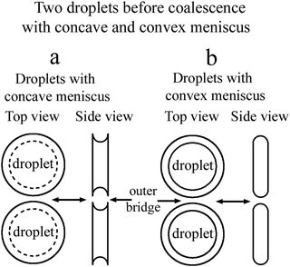
In a flat optical cell the boundary between the droplet and the environment is the curved meniscus the size of which is comparable to the scale of the bridge region. The shape of the meniscus in a flat cell essentially differs from the boundary of the 3D droplets or 2D islands or holes in the free standing films. Fig. 1(a) schematically shows the top view and the side view of two droplets with a concave meniscus when a material of droplets wets the cell surface. Fig. 1(b) depicts the top view and the side view of two droplets with a convex meniscus when a material of droplets does not wet the cell surface. The starting states for droplet coalescence are essentially different when the material of the droplets or the material of the outer environment wets the cell surface. When droplets come into contact, coalescence starts near the cell surfaces in the case of concave meniscus (a) or in the center of the cell in the case of convex meniscus (b). In a recent publication39 coalescence of isotropic droplets was investigated when the isotropic phase wets the surface. It was found that the coalescence of isotropic droplets is accompanied by the instability of the nematic bridge and the formation of nematic satellite droplets.
In the present paper, we consider the opposite case when a nematic droplet wets the cell surface. Scenarios of coalescence in this case essentially differ. It is shown that the state of droplets before coalescence (whether the droplets wet the surface or not) drastically influences the coalescence process. Fig. 2 schematically shows two droplets before coalescence with a bridge of outer material separating the droplets. In Fig. 2(a) the droplets are nematic, so the material of droplets wets the cell surface, whereas in Fig. 2(b) the material of isotropic droplet does not wet the surface. We investigate coalescence of droplets with both configurations in detail. We found that the mechanism of coalescence is essentially different in these cases. When the material of nematic droplets wets the cell surface (Fig. 2(a)) the coalescence occurs with breakup of the outer isotropic bridge via Rayleigh–Plateau instability and formation of satellite domains. When the material of isotropic liquid droplet does not wet the cell surface (Fig. 2(b)) the breakup occurs without instability and without the formation of satellite droplets. This is related to the formation of thin nematic bridges on cell surfaces due to wetting which do not lead to the Rayleigh–Plateau instability.
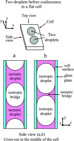 | ||
| Fig. 2 Schematic representation of nematic droplets (a) and droplets from isotropic phase (b) in a flat cell. Isotropic (a) and nematic (b) bridge between the droplets. | ||
The remainder of this paper is organized as follows. In the next section, we describe the details of the experiment. Then in Section 3 the experimental results for coalescence of nematic and isotropic droplets are presented. Discussion of the results and their comparison with existing experimental data and theory are given in Section 4. We end by a brief conclusion in Section 5.
2 Experimental details
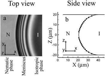
In our investigations nematic liquid crystal E7 (Synthon Chemicals) was used. Our samples have a wide coexistence region of the nematic and isotropic phases about 2.2 °C from Tsolidus ≈ 56.6 °C to Tliquidus ≈ 58.8 °C. This allows preparing nematic or isotropic droplets in the two-phase region and reliably working with them. Surface tension of the isotropic–nematic interface is about 10−5 N m−1.14,44 The dynamic viscosity near the nematic–isotropic transition is about 2 × 10⁻² Pa s.45,46 The surface anchoring strength for the isotropic–nematic interface of cyanobiphenyl materials44 is about 10−6 J m−2. The material was introduced in a flat optical cell in the isotropic phase. We employed cells with distance h between two parallel plates from 6 μm to 40 μm. The cell was placed inside a thermostatic oven (Linkam LTS120 or Mettler Toledo FP82HT). An Olympus BX51 microscope was used in the transmission mode. Observations were made between crossed polarizers. Measurements in a polarized monochromatic light (employing a color filter with λ = 545 nm) enable to determine the evolution of the bridge thickness during the coalescence process and at bridge breakup. The time evolution of the droplet shapes and their internal structure were recorded using a Baumer VCXU-02C video camera operating at a frame rate up to 400 fps with spatial resolution better than 2 pixels per μm.In our experiment the droplet radii R were larger than h. The transparent glass plates of the cells allow performing optical investigations. Cells were assembled so that the rubbing direction was the same on the two surfaces of the cell. Nematic phase wets the cell surfaces, the director is aligned parallel to the surface. In the experiment the rubbing direction of the cells was as a rule oriented under 45° with respect to polarizers. Fig. 3(a) shows the monochromatic light image of the meniscus between the nematic (left side of the image) and isotropic (dark region in the right side of the image) phases. Between crossed polarizers the isotropic region looks dark. Nematic with an oblique director orientation with respect to polarizers transmits light. Thin bright and dark stripes in the photo are related to the interference in the region of the meniscus. In the centers of the nearest black and bright stripes the nematic thickness differs by λ/2Δn, where Δn is the birefringence of nematic near the transition to the isotropic phase. The distance between stripes decreases from isotropic to nematic phase. Meniscus shape (points in Fig. 3(b)) was determined from the position of interference stripes.44 The meniscus shape is close to circular (the curve in Fig. 3(b) is a semicircle tangent to the cell surfaces), that is, the nematic phase wets the cell surface.
The experiments on the coalescence of nematic and isotropic droplets were performed in the following order. The cell with the liquid crystal was heated up to a temperature slightly exceeding the temperature at which the whole sample experienced the transition into the isotropic phase. Then the sample was cooled to a two-phase region where the nematic droplets nucleated and increased in size. When the boundaries of the two droplets approached each other, cooling was either stopped or was performed slowly (at a rate of <0.1° min−1). In contrast to islands or holes in free standing smectic films33–37 which can move along the sample, come into contact and then coalesce, droplets in glass cells usually did not move and their contact occurred as a result of their slow growth. To study coalescence of isotropic droplets in a nematic environment we employed an inverse procedure. The sample was slowly heated from the nematic phase so that isotropic droplets formed in the two-phase region and coalesced.
3 Results
We start this section with a short description of the change in the droplet shape during coalescence (Subsection 3.1). Then in Subsection 3.2 we in detail describe the transformation of the bridge structures during the early and middle stages of coalescence. We consider the transformation of the bridge region where the influence of meniscus and wetting are more essential. In Subsection 3.2(a) we describe the coalescence of nematic droplets, and in Subsection 3.2(b) the coalescence of isotropic droplets is considered.3.1 Droplet shape at coalescence (Fig. 4)
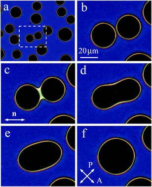
When on cooling or on heating the sample enters the two-phase region, nematic or isotropic droplets nucleate. Fig. 4(a) shows the isotropic liquid droplets formed on heating of the nematic phase. On further heating the droplets grow in size and new droplets nucleate. When, with increasing their size, two droplets contact, they coalesce. Fig. 4(b)–(f) show the coalescence process for a pair of droplets outlined by a rectangle in Fig. 4(a). At the start of coalescence a bridge between droplets is formed (bright stripe in Fig. 4(c)). The droplet shape transforms from waisted (c), (d) to elliptic (e). At the final stage, the droplet shape slowly becomes circular (f). The time of relaxation increases with increasing droplet radius. Relaxation to circular form at the final coalescence stage follows the exponential law. Relaxation time cubically depends on droplet radius which correlates with theory of viscous fuild.13 Characteristic relaxation time is about 1 s for a droplet with a final diameter of 35.2 μm and 4.8 s for a droplet with a final diameter of 59.5 μm. The transformation of the droplet shape is similar to the case of coalescence of nematic droplets when isotropic phase wets the cell surface.39 The stripe (Fig. 4(c)) between the environment nematic material vanishes with time starting from the ends. In Subsection 3.2 we describe in detail the transformation of the bridge region between large nematic (Fig. 2(a)) and isotropic (Fig. 2(b)) droplets.3.2(a) Nematic droplets coalesce (Fig. 5 and 6).
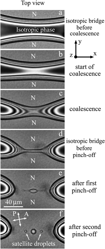
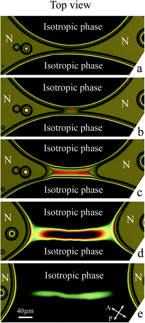
Structure transformations in the bridge region during the coalescence of large nematic (N) droplets in isotropic phase are presented in Fig. 5. Before the start of coalescence (Fig. 5(a)) the nematic droplets are separated by a bridge of the isotropic phase (dark region). As mentioned before, dark and bright stripes are related to interference in the meniscus between nematic and isotropic phases. Let us now consider transformation of the bridge region during the coalescence process.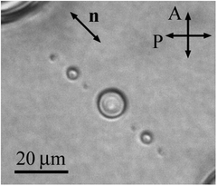 | ||
| Fig. 6 Several generations of satellite droplets formed at the breakup of the isotropic bridge during coalescence of nematic droplets. The photograph was taken in monochromatic light. h = 40 μm. | ||
Coalescence starts when the layer of the isotropic phase near the cell surface disappears and nematic material of two droplets connects (Fig. 5(b)). In Fig. 5(b) two nearest bright stripes have joined and formed a bright region that corresponds to a decrease of isotropic phase thickness by λ/2Δn and the appearance of nematic layers with a summary thickness of λ/2Δn. At the start of coalescence two thin nematic bridges are formed near the cell surfaces, whereas the transverse size of the isotropic bridge somewhat decreases. The directions of the isotropic bridge and the newly formed nematic bridge are perpendicular (correspondingly, parallel to x axis and y axis). During coalescence next stripes successively connect (Fig. 5(c)). The isotropic phase escapes from the bridge center (the curved stripes on the two sides of the bridge in Fig. 5(c) and (d) move with time in opposite directions). In the first stage of the coalescence process the transverse size of isotropic liquid bridge continues to decrease (Fig. 5(b)–(d)), and the width of nematic bridges increases. The simultaneous existence of two bridges drastically distinguishes this coalescence process from 3D coalescence or 2D coalescence, such as coalescence of islands and holes in free-standing films, where the appearance of a droplet bridge between the coalescing domains leads to breakup of the bridge of the outer material.33–37 This stage of bridge transformation is completed by the formation of a thin isotropic bridge of approximately uniform radius (Fig. 5(d)).
During the second stage of transformation the radius of the isotropic liquid bridge decreases near its ends. The decrease of the radius leads to pinch-offs near the ends of the bridge (Fig. 5(e)). As a result an elongated isotropic droplet is formed in the center. After pinch-offs the isotropic bridge ceases to exist. During these processes the isotropic liquid flow in some parts of the bridge changes its direction. The width of the elongated droplet in its center (Fig. 5(e)) becomes larger than the thin bridge (Fig. 5(d)). Then the elongated droplet also becomes unstable and secondary pinch-offs take place near the ends of the elongated droplet. Three droplets are formed and relax to circular shape (Fig. 5(f)): the larger central droplet and two small satellite droplets.
In some cases we observed the next generation of satellite droplets. Fig. 6 shows the result of breakup with the formation of a central droplet and 6 satellite droplets. Two larger droplets are the first generation of satellite droplets and four smaller droplets are the second generation of satellite droplets. The average ratio of droplet sizes in two successive generations is about 2.5. For the first time we observed very small satellite droplets with a radius of about 1 μm. We should note that multiple pinch-offs and satellite droplet formation were not observed during the 3D coalescence of droplets,9,28 2D coalescence of islands and holes,33–37 quasi-2D coalescence of liquid lenses on liquid surface41 and on thin films.42,43
3.2(b) Isotropic droplets coalesce (Fig. 7 and 8)
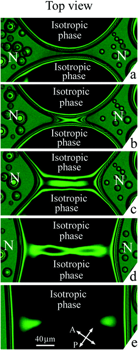
Fig. 7 and 8 show the transformation of the bridge region at coalescence of isotropic droplets in a nematic environment. Imaging was made in white light (Fig. 7) and with a green filter (Fig. 8). Before coalescence nematic bridge separates two isotropic droplets (dark regions). Fig. 7(a) and 8(a) show the bridge region right before the start of coalescence when the width of the nematic bridge is small. During the first stage of coalescence the image of the bridge region (Fig. 7(a) and 8(b)) can seem similar to Fig. 5(c) but further evolution and the results of evolution are essentially different (compare Fig. 5(d)–(f) and 7(c)–(e), 8(c)–(e)). Please note that coalescence described in Subsection 3.2(a) starts as nematic droplets contact near the cell surfaces (Fig. 5(b)) due to the concave shape of nematic meniscus (Fig. 2(a)). In the present case coalescence starts with the contact of isotropic liquid droplets in the cell center (Fig. 2(b)) where the isotropic bridge appears. The directions of the nematic and isotropic liquid bridges are perpendicular as well as in the previous case (Subsection 3.2(a)). However the bridge region is essentially different with respect to coalescence of the nematic droplets (Fig. 5(d)–(f)). The thickness of the nematic bridges decreases (the order of interference stripes decreases), but their widths remain large (Fig. 7(d) and 8(d)). Nematic wets the cell surfaces which stabilizes the bridge structure near the surfaces. With time or on small heating the nematic bridges slowly disappear breaking near the ends or in the center (Fig. 7(e) and 8(e)) without a series of sharp pinch-offs and without the formation of small satellite droplets.4 Discussion
Below we will discuss the mechanism of breakup with the formation of satellite droplets, drastically different coalescence of nematic and isotropic droplets, and the role of wetting at the cell surface during the early stage of coalescence.4.1 Coalescence of nematic droplets. Instability with pinch-off and formation of satellite droplets (Fig. 5, 6, 9)
First let us recall typical descriptions of the start of the coalescence process found in the literature. Then, we consider different scenarios of breakup of filaments and elongated fluid domains and their relation to our observations.Up to now experiments and calculations of coalescence of 3D and 2D droplets in an outer medium were mainly focused on the start of the coalescence process. In these studies it was generally assumed that the outer bridge breaks in the middle, where the bridge is most narrow, and the following evolution of the domain was studied. Analytical solution has been found for the 2D case,1 and calculations show that the asymptotic behaviour in the 3D case is the same.5 Theory predicts that depending on various parameters (such as viscosity of the droplets and the outer medium) the shape of the bridge region can differ. We should emphasize that theories described coalescence when a small droplet bridge has already been formed. At the same time the process of formation of a droplet bridge at coalescence remained unclear and was beyond the scope of previous consideration.
Numerous publications were devoted to the capillary breakup of fluid jets, filaments and long stretched droplets. Let us first review the basic analysis going back to Plateau who considered an infinite cylindrical jet of radius r0 undergoing a sinusoidal axial modulation with a wavelength λ.4,23 The perturbation of the jet arising from some external action, noise or fluctuations can be expanded in Fourier modes. Linear analysis implies that modulations with different wavenumbers evolve independently. The modulation is energetically favourable if λ > 2πr0, so such perturbations tend to increase their amplitude (note that azimuthal modulations increase the surface area and need not be considered here). With increasing the modulation wavelength the energy gain increases. To find the relative growth rate of modulations with different wavelengths, the inertia of liquid should be taken into account. The problem for the inviscid case was solved by Lord Rayleigh.24 Linear stability theory is applied in this approach. Rayleigh obtained the dispersion relation, that is, growth rate as a function of the perturbation wavelength. The fastest growing mode has wavelength λR ≈ 9r0.4 Growth of this mode would lead to breakup of the jet. When viscosity of the fluid is taken into account, the dispersion relation is modified. The wavelength of the fastest growing mode becomes larger than Rayleigh wavelength λR and increases with viscosity.4
The cases discussed previously were related to the behaviour of infinite jets. In our case the situation is more complex due to finite bridge length. Evolution of filaments of finite length, also called elongated droplets, is frequently observed and studied in experiments.4,47–50 Whereas the main results of Rayleigh–Plateau instability theory are valid, specific features of the breakup process may differ. Strongly elongated droplets can be obtained employing a rotating cell30 or shear flow of the outer fluid.48,49 As the elongated droplets contract, they can undergo so-called “end pinching” when rounded domains form at the end of the droplet and separate from it.48,50
In another type of experiments the breakup of fluid bridges between two parallel disks or two reservoirs of liquid was investigated.4,25,32,51–55 The instability of the bridge can be induced by increasing the distance between the plates,51,53–55 by gravitational force,4,52 by shear25 or by evaporation of the fluid.32 The initial form of the bridge between two plates is more similar to the shape of the outer bridge in our experiment. Linear stability theory predicts that breakup occurs at the center of the bridge. However, nonlinear dynamics strongly modifies the breakup process; first pinch-off is observed close to the bridge ends, and then satellite droplets are formed.25,53,56
Now we compare our observations with the experiments and calculations of the breakup of filaments and stretched droplets. We will analyze the evolution of the bridge both from the images of bridges (front view, Fig. 5) and from the shape of the bridge in perpendicular direction (side view, Fig. 9). Points in Fig. 9(a)–(c) give the profiles of the nematic–isotropic interface determined from the positions of interference stripes (Fig. 5). Before coalescence there is a gap between the nematic droplets in the region of the isotropic bridge (Fig. 9(a)). Because nematic phase of the droplets wets the cell surface, the meniscus of nematic droplets is concave and coalescence starts near the two surfaces (Fig. 9(b)). At the beginning of coalescence thin nematic droplet bridges appear near each surface and their thicknesses increase with time (Fig. 9(b)–(d)). The bridge from the environment material (isotropic phase) that exists before the start of coalescence behaves in the opposite way. We draw the thin isotropic bridge in the middle of the cell (Fig. 8(c) and (d)). In reality it can be located nonsymmetrically, closer to one of the boundaries. Due to surface tension the transverse shape of the isotropic bridge becomes close to circular; its radius decreases with time (Fig. 9(b)–(d)). In contrast to the relaxation of droplets to circular form, at the final stage of bridge thinning its dynamics is not described by exponential law. The bridge thinning is linear with time at the final stage with a characteristic velocity of about 30 μm s−1. The linear dependence is in agreement with the capillary viscous regime of breakup. Decrease of the bridge radius in its center was previously observed during the breaking of the bridge between two plates.51 However both in the case of a bridge between plates51 and in our case the radius in the center does not decrease to zero, as linear theory would imply. The shape of the bridge is modified, which can be attributed to the axial flow along the bridge due to large local stresses on the two sides of the bridge center. As a result, a thin bridge of nearly uniform radius r0 is formed (Fig. 5(d) and 9(d)). This cylindrical bridge becomes unstable. Modulation of the bridge radius with a maximum of thickness in the center and two minima near the ends of the bridge appears and grows (Fig. 5). This behaviour is related to nonlinearity.56 Instability starts when the bridge radius r0 becomes small, its length l is sufficiently large and the aspect ratio of the cylindrical bridge l/r0 ∼ 9.5. This value qualitatively correlates with the theoretical prediction of the optimal wavelength of capillary instability for viscous fluid λ/r0 > 9.4 Instability leads to the appearance of two thinning points with minimal radii rmin near the bridge ends. For long filaments the position of thinning points remains constant with time. We observed shift of the thinning points so that relative wavelength increases to about λ/r0 ∼ 18. Minimal radii rmin near the ends continue to decrease which leads to pinch-off (Fig. 5(e)) and the formation of an elongated droplet at the center. In all experiments we observed two symmetrical pinch-offs near the ends of the bridge (Fig. 5(e)).
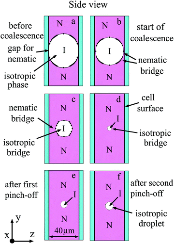 | ||
| Fig. 9 Schematic illustration of the side view of bridge region for coalescence presented in Fig. 5. Cross-cut at the middle of the cell is shown. Nematic (N) and isotropic (I) phases are indicated in the Figure. Nematic wets the cell surface. (a) Before coalescence a gap exists between two nematic droplets. After start of coalescence (b) nematic bridges appear near two cell surfaces. (b)–(d) The transverse size of the isotropic bridge decreases. (e and f) Instability of the thin isotropic bridge leads to formation of small droplets in the middle of the cell. | ||
Receding ends of the central domain also become unstable and a secondary pinch-off with the formation of a second generation of droplets takes place (Fig. 5(f)). In previous experiments on the instability of a liquid bridge between two solid plates, pinch-off was observed near the ends of the bridge,4,53 then secondary pinch-off with the formation of several generations of satellite droplets took place.25 Our results, in particular the symmetric pinch-off with respect to the bridge center and the evolution of the central elongated droplet formed as a result of initial breakup and following pinch-off (Fig. 5) are similar to the observations of liquid bridge breakup4,25,32 and to calculations employing nonlinear theory.25 For the first time we observed instability in the experiment at coalescence of nematic droplets. As in the case of jets and elongated droplets the observed behaviour is related to Rayleigh–Plateau instability. However, full theoretical description of the coalescence-induced breakup process would require a detailed consideration of the peculiarities of the studied object. Note that in the large part of the droplet the dynamics is slow. In the bridge region it can be fast and backflow effects57,58 can influence the process. At present there is no corresponding theory. We hope our experiment will initiate theoretical work in this direction.
4.2 Coalescence of isotropic liquid droplets without instability and without satellite droplets (Fig. 7, 8, 10)
Fig. 10 in a schematic way shows the side view of the bridge region for coalescence of isotropic liquid droplets depicted in Fig. 7 and 8. The nematic phase wets the cell surface and the meniscus is convex from the side of the isotropic phase (Fig. 2(b) and 10(a)). Coalescence starts in the middle of the cell with the appearance of a droplet bridge (Fig. 7(b), 8(b) and 10(b)). Instead of a thin isotropic bridge formed in the case of nematic droplet coalescence (Fig. 9), a thick isotropic bridge forms in the middle of the cell, and its thickness increases with time (Fig. 10(b) and (c)). The outer nematic bridge remains but it breaks down into two bridges near the surfaces (Fig. 10(b)–(d)). As the liquid droplet bridge grows, the outer nematic bridge becomes thinner but its width remains large since the material of the outer bridge wets the cell surfaces. In contrast to Subsection 4.1 a bridge of circular section is not formed.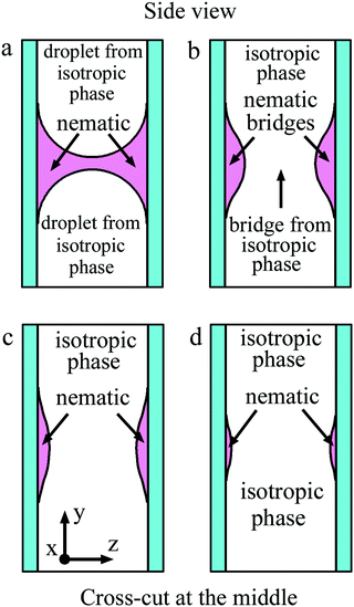 | ||
| Fig. 10 Schematic representation of the side view of the bridge region for coalescence shown in Fig. 7 and 8. Cross-cut at the middle of the cell is shown. Nematic wets the cell surface. (a) Before coalescence a gap for isotropic phase of the two droplets exists. After start of coalescence (b) a bridge from isotropic phase appears in the middle of the cell. (c) and (d) During coalescence the thickness of the isotropic bridge increases, the thickness of nematic bridges near the surfaces decreases. With time nematic bridges disappear. | ||
Let us consider the stability of a wide stripe formed near the surface. Similar to the 3D case, transformation of a thin (quasi-2D) stripe into circular droplets would be favorable if the length of the stripe which is transformed into a droplet is larger than πw, where w is the stripe width. However, in contrast to the 3D case, no Rayleigh–Plateau instability of the flat stripe takes place. Indeed, a sinusoidal modulation of the stripe width does not decrease the surface area regardless of its wavelength, so such perturbations would not spontaneously grow. Thus the mechanism of transformation of the stripes before breakup is different from the Rayleigh–Plateau instability. An additional factor effectively hindering rapid breaking of the thin outer bridge is wetting on the cell surfaces. Thin outer bridges near the surfaces exist for a long time and slowly disappear. The behavior of thin nematic bridges near the cell surfaces is in contrast with that described in the previous subsection. For a quantitative description of this process, a complex theory which accounts for the wetting of the cell surface is necessary.
Fig. 11 summarizes the behaviour observed at droplet coalescence under different wetting conditions of the material on the cell surface. The current article describes cases 1 and 2 (nematic wetting the cell surface). When nematic droplets coalesce, instability of the bridge of the outer liquid takes place and isotropic satellite droplets are formed. When isotropic droplets coalesce, no instability is observed. Cases 3 and 4 (when the isotropic phase wets the cell surface) have been studied in ref. 39. The behaviour at coalescence is opposite to 1 and 2. So we have realized a multitude of scenarios and demonstrated the crucial role of wetting of a droplet material in the coalescence process in flat cells.
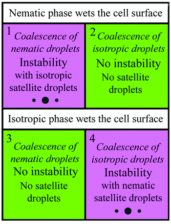 | ||
| Fig. 11 Summary of the scenarios of droplet coalescence. The wetting conditions play a key role in the development of instability and appearance of satellite droplets at coalescence. | ||
5 Conclusions
In this paper we in detail investigated the coalescence of nematic and isotropic droplets in flat optical cells. We realized the situation when both a bridge between droplets and a bridge from the environment material exist at the same time at coalescence. We found that the scenarios of coalescence of nematic and isotropic droplets are drastically different, which is related to wetting of the cell surfaces by the nematic phase. When nematic droplets coalesce, the Rayleigh–Plateau instability is observed with a series of pinch-offs and formation of satellite droplets. The Rayleigh–Plateau instability occurs with the bridge of the outer liquid since it does not wet the cell surface and the thin outer bridge in the process of coalescence is localized in middle of the cell. When isotropic droplets coalesce, the behaviour essentially differs. Two outer bridges form near the cell surfaces. Wetting of the surface by the material of the outer bridge prevents the development of the classical Rayleigh–Plateau instability and thin outer nematic bridges continuously disappear.Conflicts of interest
There are no conflicts to declare.Acknowledgements
The reported study was supported by the Russian Science Foundation under Grant 18-12-00108.Notes and references
- R. W. Hopper, Coalescence of two equal cylinders: Exact results for creeping viscous plane flow driven by capillarity, J. Am. Ceram. Soc., 1984, 67, C-262–C-264 CrossRef.
- S. Richardson, Two dimensional slow viscous flows with time-dependent free boundaries driven by surface tension, Eur. J. Appl. Math., 1992, 3, 193–207 CrossRef.
- R. E. Goldstein, A. I. Pesci and M. J. Shelley, Topology transitions and singularities in viscous flows, Phys. Rev. Lett., 1993, 70, 3043–3046 CrossRef PubMed.
- J. Eggers, Nonlinear dynamics and breakup of free-surface flows, Rev. Mod. Phys., 1997, 69, 865–929 CrossRef CAS.
- J. Eggers, J. R. Lister and H. A. Stone, Coalescence of liquid drops, J. Fluid Mech., 1999, 401, 293–310 CrossRef CAS.
- L. Duchemin, J. Eggers and C. Josserand, Inviscid coalescence of drops, J. Fluid Mech., 2003, 487, 167–178 CrossRef.
- Y. Lee and J. E. Sprittles, Capillary breakup of a liquid bridge: identifying regimes and transitions, J. Fluid Mech., 2016, 797, 29–59 CrossRef.
- X. Xia, C. He and P. Zhang, Universality in the viscous-to-inertial coalescence of liquid droplets, Proc. Natl. Acad. Sci. U. S. A., 2019, 116, 23467–23472 CrossRef CAS.
- M. Rahman, W. Lee, A. Iyer and S. J. Williams, Viscous resistance in drop coalescence, Phys. Fluids, 2019, 31, 012104 CrossRef.
- S. Perumanath, M. K. Borg, M. V. Chubynsky, J. E. Sprittles and J. M. Reese, Droplet coalescence is initiated by thermal motion, Phys. Rev. Lett., 2019, 122, 104501 CrossRef CAS.
- E. S. Pikina, B. I. Ostrovskii and S. A. Pikin, Coalescence of isotropic droplets in overheated smectic films, Soft Matter, 2020, 16, 4591–4606 RSC.
- U. Delabre, C. Richard, J. Meunier and A. M. Cazabat, Line tension of nematic pancakes at the air-water interface: Static and dynamic measurements, EPL, 2008, 83, 66004 CrossRef.
- P.-T. Brun, M. Nagel and F. Gallaire, Generic path for droplet relaxation in microfluidic channels, Phys. Rev. E: Stat., Nonlinear, Soft Matter Phys., 2013, 88, 043009 CrossRef.
- P. Oswald and G. Poy, Droplet relaxation in Hele-Shaw geometry: Application for the measurement of the nematic-isotropic surface tension, Phys. Rev. E: Stat., Nonlinear, Soft Matter Phys., 2015, 92, 062512 CrossRef.
- M. Yu, R. B. Lira, K. A. Riske, R. Dimova and H. Lin, Ellipsoidal Relaxation of Deformed Vesicles, Phys. Rev. Lett., 2015, 115, 128303 CrossRef PubMed.
- J. D. Paulsen, J. C. Burton and S. R. Nagel, Viscous to inertial crossover in liquid drop coalescence, Phys. Rev. Lett., 2011, 106, 114501 CrossRef PubMed.
- J. D. Paulsen, R. Carmigniani, A. Kannan, J. C. Burton and S. R. Nagel, Coalescence of bubbles and drops in an outer fluid, Nat. Commun., 2014, 5, 3182–3185 CrossRef PubMed.
- S. C. Case and S. R. Nagel, Coalescence in Low-Viscosity Liquids, Phys. Rev. Lett., 2008, 100, 084503 CrossRef PubMed.
- J. D. Paulsen, J. C. Burton, S. R. Nagel, S. Appathural, M. T. Harris and O. A. Basaran, The inexorable resistance of inertia determines the initial regime of drop coalescence, Proc. Natl. Acad. Sci. U. S. A., 2012, 109, 6857–6861 CrossRef CAS.
- J. D. Paulsen, Approach and Coalescence of Liquid Drops in Air, Phys. Rev. E: Stat., Nonlinear, Soft Matter Phys., 2013, 88, 063010 CrossRef PubMed.
- K. Fezzaa and Y. Wang, Ultrafast x-ray phase-contrast imaging of the initial coalescence phase of two water droplet, Phys. Rev. Lett., 2008, 100, 104501 CrossRef.
- F. Savart, Mémoire sur la Constitution des Veines liquides lancées par des orifices circulaires en mince paroi, Ann. Chim., 1833, 53, 337–386 Search PubMed.
- J. P. Plateau, Statique Expérimentale et Théoretique des Liquides Soumisaux Seules Forces Molécoulaires, Gautethier-Villars, Paris, 1873 Search PubMed.
- W. S. Rayleigh, On the instability of jets, Proc. London Math. Soc., 1878, 10, 4–13 CrossRef.
- B. M. Tjahjadi, H. A. Stone and J. M. Ottino, Satellite and subsatellite formation in capillary breaking, J. Fluid Mech., 1992, 243, 297–317 CrossRef.
- I. Cogen and S. R. Nagel, Scaling at the selective withdrawal transition through a tube suspended above the fluid surface, Phys. Rev. Lett., 2002, 88, 074501 CrossRef PubMed.
- P. Doshi, I. Cohen, W. W. Zhang, M. Siegel, P. Howell, O. Basaran and S. R. Nagel, Persistence of memory in drop breakup: The breakdown of universality, Science, 2003, 302, 1185–1188 CrossRef CAS PubMed.
- J. C. Burton and P. Taborek, Role of Dimensionality and Axisymmetry in Fluid Pinch-Off and Coalescence, Phys. Rev. Lett., 2007, 98, 224502 CrossRef CAS PubMed.
- L. G. Fel and Y. Zimmels, Rayleigh instability in liquid crystal jets, J. Exp. Theor. Phys., 2004, 98, 960–973 CrossRef CAS.
- E. Alvarez-Lacalle, J. Casademunt and J. Eggers, Pinch-off singularities in rotating Hele-Shaw flows at high viscosity contrast, Phys. Rev. E: Stat., Nonlinear, Soft Matter Phys., 2009, 80, 056306 CrossRef CAS.
- M. Yokota and Ko Okumura, Dimensional crossover in the coalescence dynamics of viscous drops confined in between two plates, Proc. Natl. Acad. Sci. U. S. A., 2011, 108, 6395–6398 CrossRef CAS.
- D. Tiwari, L. Mercury, M. Dijkstra, H. Chaudhary and J. F. Hernández-Sánchez, Post-pinch-off relaxation of two-dimensional droplets in a Hele-Shaw cell, Phys. Rev. Fluids, 2018, 3, 124202 CrossRef.
- R. Stannarius and K. Harth, Inclusions in free suspended smectic films, in Liquid Crystals with Nano and Microparticles, ed. J. P. F. Lagerwal and G. Scalia, World Scientific, Singapore, 2017, pp. 401–405 Search PubMed.
- N. S. Shuravin, P. V. Dolganov and V. K. Dolganov, Coalescence of viscous two-dimensional smectic islands, Phys. Rev. E: Stat., Nonlinear, Soft Matter Phys., 2019, 99, 062702 CrossRef CAS PubMed.
- P. V. Dolganov, N. S. Shuravin and V. K. Dolganov, Coalescence of holes in two-dimensional smectic films, Phys. Rev. E: Stat., Nonlinear, Soft Matter Phys., 2020, 101, 052701 CrossRef CAS PubMed.
- P. V. Dolganov, N. S. Shuravin, V. K. Dolganov and E. I. Kats, Dynamic of island-meniscus coalescence in free-standing films, Soft Matter, 2020, 16, 8503–8511 RSC.
- Z. H. Nguyen, K. Harth, A. M. Goldfain, C. S. Park, J. E. Maclennan, M. A. Glaser and N. A. Clark, Coalescence of Islands in Freely-Suspended Smectic Films, Phys. Rev. Res., 2021, 3, 033143 CrossRef CAS.
- P. V. Dolganov and P. Cluzeau, Influence of chirality of director configuration and droplet interaction in ferroelectric free-standing films, Phys. Rev. E: Stat., Nonlinear, Soft Matter Phys., 2008, 78, 021701 CrossRef CAS.
- P. V. Dolganov, A. S. Zverev, K. D. Baklanova and V. K. Dolganov, Dynamics of capillary coalescence and breakup: quasi-two-dimensional nematic and isotropic droplets, Phys. Rev. E: Stat., Nonlinear, Soft Matter Phys., 2021, 104, 014702 CrossRef CAS PubMed.
- J. F. Hernandez-Sanchez, L. A. Lubbers, A. Eddi and J. H. Snoeijer, Symmetric and Asymmetric Coalescence of Drops on a Substrate, Phys. Rev. Lett., 2012, 109, 184502 CrossRef CAS PubMed.
- M. A. Hack, W. Tewes, Q. Xie, C. Datt, K. Harth, J. Harting and J. H. Snoeijer, Self-Similar Liquid Lens Coalescence, Phys. Rev. Lett., 2020, 124, 194502 CrossRef CAS PubMed.
- C. Klopp, T. Trittel and R. Stannarius, Self-similarity of liquid droplet coalescence in a quasi-2D free-standing liquid-crystal film, Soft Matter, 2020, 16, 4607–4614 RSC.
- C. Klopp and A. Eremin, On droplet coalescence in a quasi-2D fluid, Langmuir, 2020, 36, 10615–10621 CrossRef CAS PubMed.
- M. Kleman and O. D. Lavrentovich, Soft Matter Physics: An Introduction, Springer, 2003 Search PubMed.
- H. Wang, T. X. Wu, S. Gauza, J. R. Wu and S.-T. Wu, A method to estimate the Leslie coefficients of liquid crystals based on MBBA data, Liq. Cryst., 2006, 33, 91–98 CrossRef CAS.
- R. Basu, D. Kinnamon, N. Skaggs and J. Womack, Faster in-plane switching and reduced rotational viscosity characteristics in a graphene-nematic suspension, J. Appl. Phys., 2016, 119, 185107 CrossRef.
- H. A. Stone and M. P. Brenner, Note on the capillary thread instability for fluids of equal viscosities, J. Fluid Mech., 1996, 318, 373–374 CrossRef CAS.
- H. A. Stone, B. J. Bentley and L. G. Lead, An experimental study of transient effects in the breakup of viscous drops, J. Fluid Mech., 1986, 173, 131–158 CrossRef CAS.
- V. Cristini, S. Guido, A. Alfani, J. Blawzdziewicz and M. Loewenberg, Drop breakup and fragment size distribution in shear flow, J. Rheol., 2003, 47, 1283–1298 CrossRef CAS.
- A. A. Castrejon-Pita, J. R. Castrejon-Pita and I. M. Hutchings, Breakup of Liquid Filaments, Phys. Rev. Lett., 2012, 108, 074506 CrossRef PubMed.
- X. Zhang, R. S. Padgett and O. Basaran, Nonlinear deformation and breakup of stretching liquid bridges, J. Fluid Mech., 1996, 329, 207–245 CrossRef CAS.
- I. Cohen, M. P. Brenner, J. Eggers and S. R. Nagel, Two Fluid Drop Snap-Off Problem: Experiments and Theory, Phys. Rev. Lett., 1999, 83, 1147–1150 CrossRef CAS.
- J. R. Savage, M. Caggioni, P. T. Spicer and I. Cohen, Partial universality: pinch-off dynamics in fluids with smectic liquid crystalline order, Soft Matter, 2010, 6, 892–895 RSC.
- D. Porter, J. R. Savage, I. Cohen, P. Spicer and M. Caggioni, Temperature dependence of droplet breakup in 8CB and 5CB liquid crystals, Phys. Rev. E: Stat., Nonlinear, Soft Matter Phys., 2012, 85, 041701 CrossRef PubMed.
- J. C. Burton, J. E. Rutledge and P. Taborek, Fluid Pinch-Off Dynamics at Nanometer Length Scales, Phys. Rev. Lett., 2004, 92, 244505 CrossRef CAS PubMed.
- J. Eggers, Drop formation – an overview, Z. Angew. Math. Mech., 2005, 85, 400–410 CrossRef.
- D. Svensek and S. Zumer, Complex backflow dynamics in nematic liquid crystals, Continuum Mech. Thermodyn., 2002, 14, 231–239 CrossRef CAS.
- A. Missaoui, E. Lacaze, A. Eremin and R. Stannarius, Observation of Backflow during the Anihilation of Topologocal Defects in Freely Suspended Smectic Films, Crystals, 2021, 11, 430 CrossRef CAS.
| This journal is © The Royal Society of Chemistry 2022 |

