 Open Access Article
Creative Commons Attribution 3.0 Unported Licence
Effect of salt on the lamellar Lα-to-MLV transformation in SDS/octanol/water under microfluidic flow†
Liva
Donina
a,
Lionel
Porcar
b and
João T.
Cabral
 *a
*a
aDepartment of Chemical Engineering, Imperial College London, London, UK. E-mail: j.cabral@ic.ac.uk; Tel: +44 207 594 5571
bInstitut Laue-Langevin, 71 Avenue des Martyrs, B.P. 156, F-38042 Grenoble Cedex, France
First published on 25th July 2022
Abstract
We investigate the effect of added (NaCl) salt and varying flow rate on the phase behaviour and flow response of a model surfactant Lα phase, sodium dodecyl sulfate (SDS)/octanol/water, using small angle neutron scattering (SANS) and polarised optical microscopy in microfluidics, supported by NMR, viscosity, conductivity and zeta potential measurements. A long (∼3 m) tubular microchannel device is employed to quantify the spatiotemporal structural evolution of the system towards multilamellar vesicles (MLV). The effect of salt is rationalised in terms of changes in membrane bending rigidity and phase stability. It is shown that ∼1.8 w/w% NaCl addition results in MLV formation within the shortest time (or equivalent lengthscale) and yields near-centrosymmetric scattering profiles characteristic of MLVs (at a reference 1 mL h−1 flow rate and ≃90 s−1 shear rate). Further salt addition yields biphasic systems that remain strongly aligned under flow, while lower salt content also increases scattering anisotropy, accompanied by higher membrane rigidity and solution viscosity. Increasing flow rate causes greater initial Lα alignment, and thus flow anisotropy, but also faster evolution towards isotropy and MLV formation.
1 Introduction
Amphiphilic membranes are formed via the noncovalent self-assembly of amphiphilic molecules, such as lipids, surfactants, or block-copolymers, into broadly planar monomolecular arrays of one or two layers, characteristic of cell membrane bilayers, and liquid crystalline surfactant lamellar Lα phases. The elastic properties of Lα membranes, namely their low compressibility and low membrane bending rigidity,1 largely govern their physical behaviour2,3 and flow response.4Generally, membrane bending rigidity is estimated by either measuring the associated thermal undulation spectrum, or by deforming the membrane and measuring its response, thus involving distinct experimental techniques and data analysis models.5 Experiments probing individual membranes are generally based on giant unilamellar vesicles (∼100 μm), observable by light microscopy, employing fluctuation spectroscopy6 or micropipette aspiration.7 Scattering and NMR techniques generally probe concentrated membrane ensembles, or stacks, where neighbouring interactions are important.1 The membrane bending rigidity is reflected on the line shape of the lamellar Bragg peak measured by small angle neutron or X-ray scattering (SANS, SAXS) which, in a Lα system can be described by the Caillé structure factor S(q) model,8–10
| S(q) ∼ (q − qh)1+η | (1) |
 | (2) |
![[B with combining macron]](https://www.rsc.org/images/entities/i_char_0042_0304.gif) is membrane compressibility modulus and d corresponds to the Lα repeat distance (d-spacing), kB is Boltzmann constant and T is temperature. Neutron or X-ray scattering, in conjunction with osmotic stress measurements11 or dynamic light scattering12 can determine both κ, and
is membrane compressibility modulus and d corresponds to the Lα repeat distance (d-spacing), kB is Boltzmann constant and T is temperature. Neutron or X-ray scattering, in conjunction with osmotic stress measurements11 or dynamic light scattering12 can determine both κ, and ![[B with combining macron]](https://www.rsc.org/images/entities/i_char_0042_0304.gif) . If
. If ![[B with combining macron]](https://www.rsc.org/images/entities/i_char_0042_0304.gif) cannot be measured by ancillary techniques, model estimations can be made, assuming electrostatic or steric interactions between adjacent membranes.11,13 The inter-membrane potential for charged planes can be obtained from the one-dimensional Poisson–Boltzmann equation, as13
cannot be measured by ancillary techniques, model estimations can be made, assuming electrostatic or steric interactions between adjacent membranes.11,13 The inter-membrane potential for charged planes can be obtained from the one-dimensional Poisson–Boltzmann equation, as13 | (3) |
![[B with combining macron]](https://www.rsc.org/images/entities/i_char_0042_0304.gif) PB can be decreased by attractive contributions of counterions near the membrane.14 Steric repulsions can also contribute to the overall
PB can be decreased by attractive contributions of counterions near the membrane.14 Steric repulsions can also contribute to the overall ![[B with combining macron]](https://www.rsc.org/images/entities/i_char_0042_0304.gif) , as described by Helfrich equation:15
, as described by Helfrich equation:15 | (4) |
Experimentally, Neutron Spin Echo (NSE) can measure shape fluctuations in Lα membranes via the intermediate scattering function I(q, t) from which κ can be directly estimated,13,16 although measurements are long (∼days), require large sample volumes (∼several mL), and experimental access is somewhat limited.1
The elastic properties of membranes can be modulated by the addition of dopants that embed within the bilayer (e.g., polymers, surfactants, alcohols, nanoparticles) or by addition of salt, thereby impacting κ. As an example, Meklesh and Kekicheff reported that addition of polyethylene glycol (PEG) to sodium dodecyl sulfate(SDS)/octanol/brine system increases membrane bending rigidity once the polymer concentration crossover from dilute to semidilute regimes is reached.14 The addition of charged surfactants has been found to both increase and decrease Lα membrane bending rigidity.17,18
Similarly, addition of salt will impact membrane bending rigidity κ in a manner that will depend on the initial membrane charge. In the case of non-ionic surfactant Lα phases, addition of salt will lead to increase in κ. For example, NaCl addition to nonionic dioleoylphosphatidylcholine (DOPC) Lα phase was reported to increase bending rigidity.19 In a different study, nonionic C15E5, upon addition of antagonistic RbBPh4 salt, was also found to increase membrane bending rigidity.13 However, other studies have indicated a decrease in κ with salt addition; for instance, the addition of NaCl to anionic dipalmitoylphosphatidyl glycerol (DDPG) surfactant has been shown to decreased membrane bending rigidity κ, interpreted as due to charge screening of steric repulsions.20
In this paper, we consider the impact of salt addition, and thus varying membrane bending rigidity, on the flow-induced transformation of a model Lα surfactant phase into multilamellar vesicles (MLVs). This Lα to MLV transformation21 has been extensively studied using different shear fields, stress and rates, using various model systems (non-ionic,22–24 cationic25,26 and anionic27,28) alongside the effect of added co-surfactants18,29 and salt.13,19 Zilman and Granek4 have proposed a theoretical model that estimates the critical shear required for the transformation in terms of the membrane properties (d and κ) and flow geometry, although experimental evidence appears unclear, with increasing membrane bending rigidity resulting in both higher13,30 or lower critical shear rates.31
To date, only a few studies have examined the coupling between Lα membrane elastic properties and their flow response.13,30,31 Here, we consider the effect of varying NaCl content on the model anionic SDS/octanol/water system in the Lα phase, building upon previous work on the flow-induced MLV phase transformation of the 2% NaCl system investigated by rheometry28,32–34 and microfluidics.35,36 We first report on the effect of NaCl under quiescent conditions using SANS, viscometry and electrophoretic measurements (conductivity and zeta potential) to quantify and distinguish the effect of charge to the membrane elastic properties. We then investigate the spatiotemporal evolution of the fluid structure employing microfluidic-SANS,37 crosspolarised optical microscopy and 2H NMR, and seek to rationalise the behaviour in terms of the Lα membrane properties. We consider both the effect of varying NaCl at a constant flow rate, and the effect of varying flow rate for a select NaCl concentration, and contrast the findings with our previous observations36 under oscillatory microfluidic flow.
2 Methods
2.1 Sample preparation
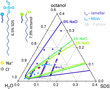
Following phase mapping by optical microscopy (Fig. S1, ESI†), the selected Lα concentration, namely 6.5% SDS, 7.9% octanol and 85.6% brine, denoted with a red star in Fig. 1, was prepared with varying salt content. First, brine solutions with concentrations of 0, 1, 5, 10, 15, 18, 20, 22 and 25 g L−1 NaCl (ACS Reagent, ≥99.0%) in D2O (Sigma-Aldrich, 99.9 atom% D) corresponding to 0, 17, 86, 171, 257, 308, 342, 376 mM and 427 mM were prepared. These concentrations will be denoted as 0, 0.1, 0.5, 1, 1.5, 1.8, 2.0, 2.2, 2.5 w/w% NaCl in the paper referring to amount of NaCl in brine solution. Following that, 0.65 g (2.25 mmol) of Sodium Dodecyl Sulphate, SDS (Sigma-Aldrich BioXtra, ≥99.0%) were dissolved in 9.52 g (427 mmol) of D2 O brine solution made of 0, 1, 5, 10, 15, 18, 20, 22 and 25 g L−1 NaCl. Dissolution was aided by heating to 30 °C until SDS had dissolved and allowed to cool to room temperature. Then, 0.790 g (6.07 mmol) of 1-octanol (Sigma-Aldrich, anhydrous, ≥99%) was added to each of the SDS/brine mixture and stirred for 2 min at 1000 rpm until fully incorporated. The resulting solutions were left to equilibrate for 48 h to mitigate any inadvertent shear effects during sample preparation. The same procedure was employed to prepare samples made for microfluidic experiments but only 1.5%, 1.8%, 2.0% and 2.2% samples were prepared, given their relatively lower viscosity (Fig. S2 (ESI†), 5000–10![[thin space (1/6-em)]](https://www.rsc.org/images/entities/char_2009.gif) 000 mPa s) and thus suitability for microfluidic flow.
000 mPa s) and thus suitability for microfluidic flow.
2.2 Static SANS and data fitting
SANS experiments were performed on the D22 spectrometer at the Institut Laue Langevin, Grenoble. Static measurements used ‘banjo’ Hellma cells (1 mm path length) with first detector and collimator distance of 5.6 m, second detector distance at 1.4 m and neutron wavelength λ = 6 Å. The measured wavevector q range was 0.01 to 0.8 Å−1 and the transmission of the samples was relatively high (>0.8) with low background values of ∼0.2 cm−1. The sample rack was kept at room temperature, 25 °C. The data were reduced with GRASP software and data fitting (of radially- and sector-averaged spectra) was performed with SasView 5.0.2, employing the random head-tail sheet with Caillé structure factor model and the fitted parameters compared for the different NaCl concentrations.2.3 Viscosity measurements
Viscosity shear sweep measurements (Fig. S2, ESI†) were performed using an Anton Paar MCR 302 rheometer equipped with cone plate cell (part no. 79040). Samples investigated were with 0, 0.5, 1.0, 1.5 and 2.0% NaCl concentrations. Each sample was kept at 25 °C, with the gap between the cone-plate set to 0.2 mm and shear sweep performed from 0.1 to 2000 s−1 with 20 points per decade, maintaining each shear rate for 20 seconds. The viscosity was measured at low 0.1 s−1 shear rate value and high 1000 s−1 shear rate.2.4 Zeta potential and conductivity
Zeta potential and conductivity measurements for micellar SDS/water solutions, and lamellar SDS/octanol/water, were collected using a Litesizer 500 and a Omega cuvette (225288) by injecting 1 mL of sample for every NaCl concentration and rinsing the cuvette in-between runs with DI water. The temperature of the cell was set to 25 °C and the sample was equilibrated for 1 min, after which 3 measurements with 20 runs were performed. The Zeta potential ζ was estimated via the Helmholtz–Smoluchowski equation38 where μ is the electrophoretic mobility measured experimentally, η is the viscosity of the solution with dielectric constant εr and ε0 is the vacuum permittivity. Conductivity of DI water with various NaCl concentrations was measured with with a Hanna instruments multimeter (HI-2020) equipped with conductivity probe (HI-763100).
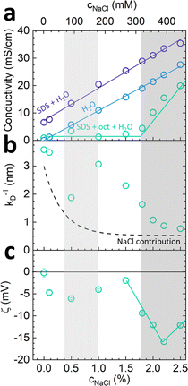
The conductivity of micellar SDS/water and water increases linearly with NaCl at all concentrations investigated, as shown in Fig. 2a. By contrast, the conductivity of the lamellar SDS/octanol/water system remains largely unchanged up to ∼1.8–2% NaCl, indicating charge condensation at the membrane surface, and then increasing linearly beyond this threshold, in agreement with the onset of demixing (Fig. 1). This behaviour is qualitatively in line with expectations from Manning theory for counterions condensation on spherical and planar geometries.39 The Debye length  , where n is the number charge density and e is the electric unit charge, was first estimated assuming that only Na+ and Cl− ions contribute to number charge density,13 yielding values between 2.32 and 0.46 nm with increasing NaCl concentration, as shown by the dashed line in Fig. 2b. A more accurate estimate utilises conductivity Kc measurements, as
  , where D is diffusion constant for Na+ and Cl− ions, D = 1.7 μm2 ms−1,40 shown as markers. The dip around 0.5–1% NaCl (shaded) coincides with the isoelectric point for this system. Zeta potential measurements are shown in Fig. 2c, approximately following the results of Fig. 2a and b. Specifically, ζ decreases around 1.8–2% NaCl, beyond which the system demixes.
2.5 Serpentine channel microfluidic setup
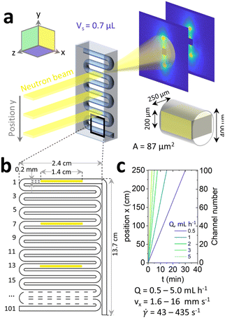
A commercially available serpentine, ∼3 m long, tubular microfluidic device etched in high optical and neutron transmittance crown glass35,41,42 (Dolomite Microfluidics, ref. 3000281) was selected for these experiments. The device was fitted with a 30 cm long inlet and outlet polytetrafluoroethylene (PTFE) tubing (Cole Parmer, ref. WZ-06406-60, i.d. = 0.79 mm). The sample was slowly poured onto the barrel of a 20 mL stainless steel syringe, and mounted on a high-pressure PHD ULTRA 4400 syringe pump (both Harvard Apparatus). The extremity of the long serpentine channel outlet was connected to the syringe (input); two of three access ports were closed and the remaining one was used as outlet and connected to a waste container. The sample was infused for 60 min to reach a steady state at 0.5–5 mL h−1 equivalent to 1.6–16 mm s−1 and wall shear rates of ∼40–400 s−1 (estimated following43 as![[small gamma, Greek, dot above]](https://www.rsc.org/images/entities/i_char_e0a2.gif) = (4Q/πReq3), where Q is volumetric flow rate and Req is the equivalent radius of an ellipsoid calculated as 2A/P with A is the cross-sectional area, 0.086 mm2, and P the perimeter, 1.08 mm). Oscillatory rheology data for the 2% NaCl reference system44 indicate a G′ and G′′ crossover at ∼0.45 s−1 corresponding to characteristic timescales of ∼2 s. The flow conditions examined can thus be considered ‘strong’, and well within the shear regime expected for MLV formation.32 Measurements were recorded for every channel section with optical microscopy and every 7th channel section for SANS. The position of the fluid on the microfluidic chip was calculated inlet length + serpentine channel section number × 24 mm (i.e., the length of each section). Flow profiles obtained by PIV of the fluid in the serpentine channel are given in Fig. S3 (ESI†) and showed plug-like flow.
= (4Q/πReq3), where Q is volumetric flow rate and Req is the equivalent radius of an ellipsoid calculated as 2A/P with A is the cross-sectional area, 0.086 mm2, and P the perimeter, 1.08 mm). Oscillatory rheology data for the 2% NaCl reference system44 indicate a G′ and G′′ crossover at ∼0.45 s−1 corresponding to characteristic timescales of ∼2 s. The flow conditions examined can thus be considered ‘strong’, and well within the shear regime expected for MLV formation.32 Measurements were recorded for every channel section with optical microscopy and every 7th channel section for SANS. The position of the fluid on the microfluidic chip was calculated inlet length + serpentine channel section number × 24 mm (i.e., the length of each section). Flow profiles obtained by PIV of the fluid in the serpentine channel are given in Fig. S3 (ESI†) and showed plug-like flow.
2.6 Microscopy
Following 60 min infusion of the sample onto the chip, the flow was stopped and microscopy images were then acquired with Olympus BX41 reflection microscope equipped with cross-polarised filters (U-AN-2 analyser and U-PO3 polariser). Image capture was done with a Basler acA2000-165um camera controlled with PylonViewer using 10×/0.25 Ach and 50×/0.50 MPlanFLN Olympus objectives under 10![[thin space (1/6-em)]](https://www.rsc.org/images/entities/char_2009.gif) 000 μs and 200
000 μs and 200![[thin space (1/6-em)]](https://www.rsc.org/images/entities/char_2009.gif) 000 μs exposure time respectively. Data were analysed with ImageJ by measuring the average light intensity and FFT for images acquired along the serpentine channel.
000 μs exposure time respectively. Data were analysed with ImageJ by measuring the average light intensity and FFT for images acquired along the serpentine channel.
2.7 Microfluidic-SANS
The microfluidic chip was mounted on a micromachined aluminium frame, thermalised to 25 °C, on the D22 spectrometer configured as described above. A neutron beam slit mask with dimensions 1.4 cm × 200 μm was used to define the beam footprint, within the bounds of the microdevice dimensions, resulting in a scattering volume of 0.7 μL (given the 0.25 mm sample pathlength, i.e. channel depth). The device was illuminated in the neutral flow direction (z in Fig. 3a), probing the xy plane. The channel was aligned with the neutron beam by iteratively scanning the empty chip and tracking the scattering and transmission signals along x and y directions until a microchannel map is resolved. Continuous microfluidic experiment was performed for 4 different NaCl concentrations (1.5, 1.8, 2.0 and 2.2%) scanning every 7th channel section, as shown in Fig. 3b. As above, the data were reduced with GRASP, sector averaged, and fitted with SasView 5.0.2 employing the random head-tail sheet with Caillé structure factor model.3 Results
3.1 The effect of salt on the Lα phase
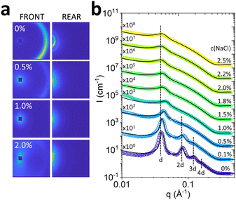
The effect of salt on the Lα phase was initially investigated under quiescent conditions with optical microscopy (Fig. 1, an Fig. S1, ESI†) and SANS. 2D scattering images (Fig. 4a, for front and rear detectors) show higher order diffraction orders for 0% NaCl that gradually disappear with increasing NaCl concentrations.The radially-averaged scattering profiles I(q) exhibit equidistant Bragg peaks (q* ≃ 0.04 Å−1, 2q* ≃ 0.08 Å−1, 3q* ≃ 0.12 Å−1 and 4q ≃ 0.16 Å−1) indicating the presence of bilayer structures characteristic of Lα phases (Fig. 4b). The higher order features45 can be disturbed by fluctuations of the Lα sheets.46,47 Indeed, we observe a decrease in membrane ordering, indicated by the disappearance of secondary, tertiary and quaternary Bragg peaks upon the addition of NaCl (Fig. 4b). The decrease in Lα ordering was accompanied by a decrease in low shear rate (0.1 s−1) viscosity, which follows a linear trend up to 1.0% NaCl addition, and then largely remains unchanged at higher salt (detailed in Fig. S2b, ESI†).
The I(q) profiles were fitted with the Caillé structure factor model, shown by the solid lines in Fig. 4b, and detailed in Fig. S4–S6 (ESI†). The Caillé parameter η was found to increase rapidly with the addition of NaCl, as shown in Fig. 5a, reaching a plateau of 1, which is the limit of the model assumptions. The solid line is an exponential rise to maximum, employed as a guide to the eye. An approximate d-spacing of 150 Å was observed across all NaCl concentrations, although varying from 156 Å at 0% NaCl, and dropping to 135 nm at 1%, near the 1![[thin space (1/6-em)]](https://www.rsc.org/images/entities/char_2009.gif) :
:![[thin space (1/6-em)]](https://www.rsc.org/images/entities/char_2009.gif) 1 molar ratio of SDS
1 molar ratio of SDS![[thin space (1/6-em)]](https://www.rsc.org/images/entities/char_2009.gif) :
:![[thin space (1/6-em)]](https://www.rsc.org/images/entities/char_2009.gif) NaCl. The bilayer thickness δ was calculated as 2(ltail + lhead) remains largely unchanged upon the addition of NaCl (Fig. 5a) indicating no appreciable swelling.
NaCl. The bilayer thickness δ was calculated as 2(ltail + lhead) remains largely unchanged upon the addition of NaCl (Fig. 5a) indicating no appreciable swelling.
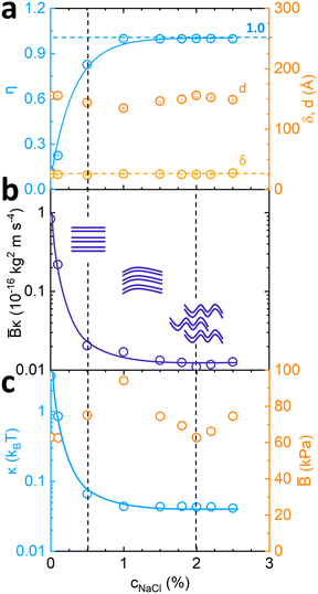 | ||
Fig. 5 Fitted parameters from Fig. 2 according to the Caillé structure factor model. (a) Caillé parameter η and Lα spacing d dependence on NaCl concentration; (b) estimated ![[B with combining macron]](https://www.rsc.org/images/entities/i_char_0042_0304.gif) κ value dependence on NaCl concentration, where κ value dependence on NaCl concentration, where ![[B with combining macron]](https://www.rsc.org/images/entities/i_char_0042_0304.gif) is the compressibility modulus and κ is membrane bending rigidity, and accompanying schematics; (c) calculated is the compressibility modulus and κ is membrane bending rigidity, and accompanying schematics; (c) calculated ![[B with combining macron]](https://www.rsc.org/images/entities/i_char_0042_0304.gif) values from values from  and corresponding κ from and corresponding κ from ![[B with combining macron]](https://www.rsc.org/images/entities/i_char_0042_0304.gif) κ model fit estimates. κ model fit estimates. | ||
From the fitted η values and eqn (2), ![[B with combining macron]](https://www.rsc.org/images/entities/i_char_0042_0304.gif) κ was estimated and found to decrease monotonically with increasing NaCl concentration, as shown in Fig. 5b. Theoretical
κ was estimated and found to decrease monotonically with increasing NaCl concentration, as shown in Fig. 5b. Theoretical ![[B with combining macron]](https://www.rsc.org/images/entities/i_char_0042_0304.gif) estimates were obtained by eqn (3) assuming only electrostatic contributions, and are plotted in Fig. 5c (including steric contributions shown in Fig. S7, ESI†). These indicate a non-monotonic behaviour upon addition of NaCl with highest value of 95 kPa when SDS
estimates were obtained by eqn (3) assuming only electrostatic contributions, and are plotted in Fig. 5c (including steric contributions shown in Fig. S7, ESI†). These indicate a non-monotonic behaviour upon addition of NaCl with highest value of 95 kPa when SDS![[thin space (1/6-em)]](https://www.rsc.org/images/entities/char_2009.gif) :
:![[thin space (1/6-em)]](https://www.rsc.org/images/entities/char_2009.gif) NaCl molar ratio is 1
NaCl molar ratio is 1![[thin space (1/6-em)]](https://www.rsc.org/images/entities/char_2009.gif) :
:![[thin space (1/6-em)]](https://www.rsc.org/images/entities/char_2009.gif) 1 (c(NaCl) = 1%) and subsequent drop in value until phase transition boundary conditions are reached around 2% NaCl (Fig. 5c). The membrane sheet schematics illustrate the decrease in stiffness and long range order induced by the salt addition. Parameter κ was estimated from model fitting results and theoretical
1 (c(NaCl) = 1%) and subsequent drop in value until phase transition boundary conditions are reached around 2% NaCl (Fig. 5c). The membrane sheet schematics illustrate the decrease in stiffness and long range order induced by the salt addition. Parameter κ was estimated from model fitting results and theoretical ![[B with combining macron]](https://www.rsc.org/images/entities/i_char_0042_0304.gif) calculations indicating an overall decrease in membrane bending rigidity (Fig. 5c) from 3.2 kBT to 0.04 kBT. This decreasing trend is consistent with that of the Debye length kD−1 (shown in Fig. 2b) indicating kD−1 ≃ 3.58 nm at low NaCl concentrations, decreasing to ≃0.78 nm at high NaCl, thus corresponding to approximately 1/4 to 1/20 of the lamellar d-spacing. A previous study of salt addition to dipalmitoylphosphatidylglycerol (DPPG)20 also reported a decrease in kD−1 with decreasing κ, as expected for reduced electrostatic repulsions.
calculations indicating an overall decrease in membrane bending rigidity (Fig. 5c) from 3.2 kBT to 0.04 kBT. This decreasing trend is consistent with that of the Debye length kD−1 (shown in Fig. 2b) indicating kD−1 ≃ 3.58 nm at low NaCl concentrations, decreasing to ≃0.78 nm at high NaCl, thus corresponding to approximately 1/4 to 1/20 of the lamellar d-spacing. A previous study of salt addition to dipalmitoylphosphatidylglycerol (DPPG)20 also reported a decrease in kD−1 with decreasing κ, as expected for reduced electrostatic repulsions.
3.2 Effect of NaCl on the lamellar phase under continuous microfluidic flow (fixed flow rate)
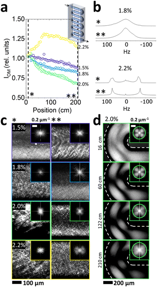
The effect of NaCl addition on the flow response of the Lα phase under continuous microfluidic flow was examined by a combination of crosspolarised optical microscopy, 2H NMR and SANS. At a fixed flow rate of 1 mL h−1, the residence time of the fluid within the microchannel length probed was ∼12 min. In general, the correspondence between position, channel section, and residence time for different flow rates is illustrated in Fig. 3c. Given the higher viscosities of low NaCl systems, the following concentrations were selected for microfluidic experiments at fixed flow rate of 1 mL h−1: 1.5, 1.8, 2.0 and 2.2% NaCl, in order to ensure the safe operation of the microdevice within a pressure operating range below 30 bar. (Pressure drop estimations are shown in Fig. S3c (ESI†), based on the Hagen–Poiseuille equation Δp = 8πμLQ/A2 where L is the channel length, Q is the volumetric flow rate, μ is dynamic viscosity and A the cross-sectional area of the channel). The system was allowed to equilibrate for ∼1 h, greatly exceeding the residence time of ∼12 min (at 1 mL h−1), at an average flow velocity ∼3.21 mm s−1. The corresponding wall shear rate is estimated43 at ≃87 s−1, within the regime in which Lα-to-MLV transformation was previously observed.32,48,49Optical birefringence measurements at the centre of each serpentine channel section (2.4 cm length) showed a decrease in (crosspolarised) light intensity along microchannel position, as shown in Fig. 6a, for NaCl concentrations between 1.5–2%, beyond which (2.2% NaCl) the trend is reversed. Given that light intensity scales approximately with feature size, the results suggest a size decrease and ordering of the characteristic fluid structures. Complementary 2H NMR data were acquired at reference start (*) and end (**) positions, illustrated for 1.8% and 2.2% NaCl in Fig. 6b. The single peak observed at 1.8% is characteristic of an isotropic fluid, contrasting with the dual peaks of 2.2%, expected for an anisotropic fluid. We thus expect the former to correspond to MLVs and the latter to an oriented lamellar sheet structure. Further the end-channel (**) data of 1.8% NaCl shows a narrowing of the peak upon microflow, expected for increasing uniformity in MLV size.
Optical images acquired at the channel entrance and at position 210 cm are indicated with * and ** in Fig. 6c, corroborating a varying degree of ordering amongst the 1.5–2.2% NaCl samples. A fine, regular texture is observed for the resulting fluid structure (**) for 1.8 and 2.0% NaCl, accompanied by FFTs exhibiting a cloverleaf pattern. Structures observed at the bends of the serpentine channel sections, shown in Fig. 6d, were of higher overall average light intensity, reflecting the additional rotational component of the shear flow. Overall, while the light intensity and MLV texture dimensions decrease along the microchannel position, these do not reach a plateau, indicating that a morphology of regularly packed onions is not attained within the experimental timescales. Employing oscillatory flow and contraction-expansion flows, enabling longer residence times of ∼2 h, we have previously observed an asymptotic optical characteristics after approximately 60 min shearing times at similar shear rate regime.36
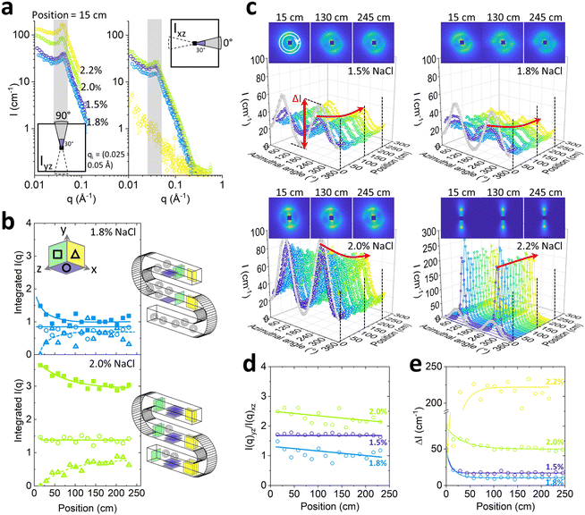
In order to resolve the nanoscale arrangement of the Lα structure, we employed microfluidic-SANS and a narrow, rectangular, beam slit (1.4 cm × 200 μm) precisely aligned along the horizontal channel sections, as shown in Fig. 3b, illuminating a 0.7 μL sample volume. Given the low illuminated volume (0.7 μL), each SANS spectrum was recorded for 20 min to acquire adequate statistics. The centre of every 7th channel section, along the y direction, was sampled, corresponding to 17 channel positions along the serpentine channel, as illustrated in Fig. 5b.
The scattering data at the start of the microchannel are generally anisotropic, as expected for aligned Lα sheets, for all NaCl concentrations. Sector analysis of I(q) reveals greater alignment along the normal (xz) direction to flow, than along the flow direction, illustrated in Fig. 7a for channel position 15 cm. The scattering varies non-monotonically with NaCl content and is lowest, and least anisotropic for 1.8% NaCl; at the highest NaCl concentration investigated, 2.2%, the anisotropy is greatest and no scattering peak is visible along the flow direction (xz). This behaviour is expected for MLVs at 1.8% and sheets a 2.2% NaCl.
Further analysis of the evolution of the alignment along the chip was carried out by integrating the scattering intensity under the Bragg peak (within 0.025 ≤ q ≤ 0.05 Å−1) as a function of channel position, as shown in Fig. 7b for 1.8% and 2.0% NaCl. The integrated intensity along the flow xz, and perpendicularly to the flow yz, is shown by ○ and Δ markers respectively. The relative fraction of sheets on xy plane cannot be measured directly, but its evolution along channel position was estimated by subtracting the sum of intensities on the yz and xz planes and subtracting their initial value, i.e. at the start of the channel. In this way, assuming that the overall scattering integral remains approximately constant within this q-range, the intensity in the ‘missing plane’ corresponding to the fraction of sheets exchanged into xy plane can be inferred, indicated by ΔIxy in terms of intensity. In the case of 1.8%, the relative sheet alignment approaches a similar end point, implying that the populations of the sheets in all principal directions are approximately equal, and this isotropic structure supports the formation of MLVs. The alignment observed for 2.0% NaCl is evidently not equal at this channel position, but gradually evolves to become more isotropic along the channel, compatible with partial MLV formation.
The evolution of the orientational order under flow for each NaCl concentration was further examined by the azimuthal analysis of the 2D scattering spectra, integrated within a narrow q range 0.035–0.045 Å−1 (Fig. 7c). In the case of 1.5% and 1.8% NaCl, anisotropy decreased rapidly along the channel position, while for 2.0% NaCl, the anisotropy decreases modestly and the lamellar sheets remain largely aligned within the microchannel length (up to ∼250 cm) and flow time (∼12 min). By contrast, the system with 2.2% NaCl content remains highly aligned throughout, as expected for lamellar sheets under shear flow; from the optical phase mapping data, this concentration corresponds to the onset of demixing.
These results corroborate the sector analysis provided in Fig. 7b, in terms of the absolute peak intensity evolution towards more isotropic structures, in particular for the 1.8% NaCl system. Fig. 7b and c show the ratio between I(q)yz and I(q)xz populations (Fig. 7d) and the maximum amplitude of the azimuthal intensity variation, termed ΔI (Fig. 7e), as a function of channel position. The results are consistent to those reported by optical microscopy in Fig. 6a, albeit the SANS data readily reach a plateau value within relatively short channel travel distances (∼25–100 cm). In terms of NaCl content, the systems can be readily ranked from iso- to anisotropic, as 1.8%, 1.5%, 2.0% and finally 2.2% NaCl. The fact that the SANS data exhibit asymptotic behaviour within short channel distances (and thus times) is expected given the nanoscale dimensions probed, while the larger, micronscale regular arrangements probed by optical microscopy evolve subsequently and refine over much longer times.36
3.3 Effect of varying microfluidic flow rate on the lamellar phase (fixed salt content)
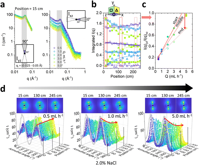
We next consider the effect of varying flow magnitude on the Lα-to-MLV transformation by investigating flow rates 0.5, 1.0, 2.0, 3.0 and 5.0 mL h−1 with microflow-SANS at a fixed 2.0% NaCl concentration, for consistency with previous work on this system. These flow rates yield wall shear rates estimates of 40–400 s−1, in the range expected for MLV formation for this system (10–1000 s−1),32 Comparing the integrated area of radially averaged I(q) sectors parallel (xz) and orthogonal (yz) to the flow, shown in Fig. 8a, follows that increasing flow rate has the dual effect of (i) inducing a greater initial lamellar sheet alignment, while also (ii) causing a more rapid decrease in anisotropy subsequently, as shown in Fig. 8b and c. The latter plots the ratio of the integrated sector intensities I(q)yz/I(q)xz, which increases approximately linearly with flow rate, and decreases with microchannel position. Direct observation of 2D scattering images, in Fig. 8d, shows that the anisotropic profiles evolve gradually along channel position, and the azimuthal analyses for 0.5, 1.0 and 5.0 mL h−1 quantify the decrease in anisotropy at the higher flow rates (1.0 and 5.0 mL h−1 shown) but exhibits virtually no change at the lowest rates of 0.5 mL h−1 (see Fig. S8 (ESI†) for 2.0 and 3.0 mL h−1). While the flow alignment of the Lα phase is expected and widely reported (e.g., ref. 35 and 50), the subsequent decrease in anisotropy under microfluidic flow indicates a gradual evolution towards MLVs, within the accessible residence time windows. Previous mechanistic studies of MLV formation suggest that lamellar sheets first align with the flow and experience a suppression of membrane undulations,4,51 eventually resulting in vesicle formation at sufficiently high shear rates and longer times.By contrast, oscillatory flows can potentially facilitate MLV-formation by selecting a different pathway.22 From a practical viewpoint, oscillatory flow fields also permit a decoupling between flow rate and residence time (which are otherwise constrained as illustrated in Fig. 3c), and thus the investigation of arbitrarily long shearing times. In Fig. S9 (ESI†), we contrast the effect of continuous (this work) and oscillatory36 flows on the Lα-to-MLV transformation on the same system. Overall, we find that the transformation rate is greater for oscillatory flow under comparable velocity and wall shear rate conditions (Fig. S9d, ESI†), highlighting the role of rotational flow components and acceleration/deceleration often found in practical flow nozzles used in MLV generation by flow processing.
4 Conclusions
We have considered the effect of salt addition (0–2.5% NaCl) on the phase behaviour and microstructure of a model Lα system, namely 6.5% SDS/7.9% octanol/85.6% brine, known to undergo a lamellar-to-MLV transition under flow. Salt addition was found to decrease Lα ordering, increase the Caillé parameter, and correspondingly decrease![[B with combining macron]](https://www.rsc.org/images/entities/i_char_0042_0304.gif) κ, the product of membrane compressibility modulus and bending rigidity, while the membrane thickness remained largely unchanged, and the d-spacing varied non-monotonically. The effect of flow was examined using a serpentine microfluidic device, consisting of a ∼3 m long tubular microchannel, operated in continuous flow, using polarised optical microscopy and SANS. Owing to operating pressure limits of the microdevice, and the high viscosity of the Lα system, NaCl content >1.5% were investigated under flow. Salt addition was found to promote MLV formation up to a crossover point between 1.8 and 2.0% NaCl.
κ, the product of membrane compressibility modulus and bending rigidity, while the membrane thickness remained largely unchanged, and the d-spacing varied non-monotonically. The effect of flow was examined using a serpentine microfluidic device, consisting of a ∼3 m long tubular microchannel, operated in continuous flow, using polarised optical microscopy and SANS. Owing to operating pressure limits of the microdevice, and the high viscosity of the Lα system, NaCl content >1.5% were investigated under flow. Salt addition was found to promote MLV formation up to a crossover point between 1.8 and 2.0% NaCl.
Fig. 9 provides an overview of our findings, in terms of the scattering observables, fitted membrane properties and accompanying lamellar schematics. Fig. 9a shows the terminal (minimum) value Imin of the cross-polarised light intensity (top), and the azimuthal intensity amplitude at Bragg peak, ΔImin, measured at the end position measured along the serpentine channel (bottom), as a function of NaCl concentration. At a fixed 2% NaCl addition, we examined the effect of increasing flow rate, which was found to increase the initial alignment of the Lα phase, and thus increase flow anisotropy, but also subsequently cause a faster decrease in anisotropy as a function of time, toward MLV formation. Fig. 9b then correlates ΔImin with the fitted ![[B with combining macron]](https://www.rsc.org/images/entities/i_char_0042_0304.gif) κ parameter obtained from quiescent SANS data, exhibiting a minimum value corresponding to the 1.8% NaCl concentration with
κ parameter obtained from quiescent SANS data, exhibiting a minimum value corresponding to the 1.8% NaCl concentration with ![[B with combining macron]](https://www.rsc.org/images/entities/i_char_0042_0304.gif) κ ≃ 0.125 × 10⁻¹⁶ kg2 ms−1; for this system, further decreasing
κ ≃ 0.125 × 10⁻¹⁶ kg2 ms−1; for this system, further decreasing ![[B with combining macron]](https://www.rsc.org/images/entities/i_char_0042_0304.gif) κ leads to the onset of demixing, and therefore does not facilitate MLV formation. The apparent inversion of the trend between 2.0 and 2.2% NaCl is likely due to the fact that the latter is within the biphasic region. An optical image taken near the channel inlet and outlet for the 1.8% NaCl concentration is included as inset, illustrating the change in optical texture and intensity effected by the microchannel flow. Our combined microfluidic SANS and optical approach is thus able to relate Lα membrane properties to continuous flow behaviour in a tubular geometry, relevant to most practical flow processing of such fluids, relating MLV formation to the effect of salt, and establishing 1.8% NaCl as an ‘optimal’ condition for this system.
κ leads to the onset of demixing, and therefore does not facilitate MLV formation. The apparent inversion of the trend between 2.0 and 2.2% NaCl is likely due to the fact that the latter is within the biphasic region. An optical image taken near the channel inlet and outlet for the 1.8% NaCl concentration is included as inset, illustrating the change in optical texture and intensity effected by the microchannel flow. Our combined microfluidic SANS and optical approach is thus able to relate Lα membrane properties to continuous flow behaviour in a tubular geometry, relevant to most practical flow processing of such fluids, relating MLV formation to the effect of salt, and establishing 1.8% NaCl as an ‘optimal’ condition for this system.
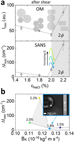 | ||
Fig. 9 Optical and SANS intensity dependence on NaCl concentration at a fixed ‘end’ channel position 245 cm. (a) Optical (top) and SANS azimuthal (bottom) intensity dependence on NaCl concentration and flow rate, with accompanying schematics. The dashed lines are guides to the eye. Qualitative effect of flow rate at a reference 2% NaCl concentration is indicated with arrows; (b) SANS azimuthal intensity ΔImin as a function of ![[B with combining macron]](https://www.rsc.org/images/entities/i_char_0042_0304.gif) κ computed from the quiescent data in Fig. 4b. κ computed from the quiescent data in Fig. 4b. | ||
Conflicts of interest
There are no conflicts to declare.Acknowledgements
We thank the Institut Laue Langevin (Grenoble) for beamtime; data available on http://doi.ill.fr/10.5291/ILL-DATA.9-10-1651 (static SANS) and http://doi.ill.fr/10.5291/ILL-DATA.9-10-1706 (flow SANS). We thank EPSRC and Imperial College London for a PhD studentship for LD. JTC acknowledges the Royal Academy of Engineering (RAEng, UK) and Procter & Gamble for funding a Research chair.References
- R. Dimova, Adv. Colloid Interface Sci., 2014, 208, 225–234 CrossRef CAS PubMed.
- M. Gradzielski, Curr. Opin. Colloid Interface Sci., 1998, 3, 478–484 CrossRef CAS.
- D. Andelman, Handb. Biol. Phys., 1995, 1, 603–642 Search PubMed.
- A. Zilman and R. Granek, Eur. Phys. J. B, 1999, 11, 593–608 CrossRef CAS.
- D. Bochicchio and L. Monticelli, Adv. Biomembr. Lipid Self-Assem., 2016, 23, 117–143 CAS.
- A. C. Rowat, P. L. Hansen and J. H. Ipsen, Europhys. Lett., 2004, 67, 144–149 CrossRef CAS.
- G. H. Sagar and J. R. Bellare, J. Phys. Chem. B, 2009, 113, 13805–13810 CrossRef CAS PubMed.
- D. Roux and C. Safinya, J. Phys., 1988, 49, 307–318 CrossRef.
- F. Nallet, R. Laversanne and D. Roux, J. Phys. II Fr., 1993, 3, 487–502 CrossRef CAS.
- R. Zhang, S. Tristram-Nagle, W. Sun, R. L. Headrick, T. C. Irving, R. M. Suter and J. F. Nagle, Biophys. J., 1996, 70, 349–357 CrossRef CAS PubMed.
- G. Brotons, M. Dubois, L. Belloni, I. Grillo, T. Narayanan and T. Zemb, J. Chem. Phys., 2005, 123, 1–18 CrossRef PubMed.
- M.-F. Ficheux, A.-M. Bellocq and F. Nallet, J. Phys. II, 1995, 5, 823–834 CrossRef CAS.
- Y. Kawabata, R. Bradbury, S. Kugizaki, K. Weigandt, Y. B. Melnichenko, K. Sadakane, N. L. Yamada, H. Endo, M. Nagao and H. Seto, J. Chem. Phys., 2017, 147, 034905 CrossRef CAS PubMed.
- V. Meklesh and P. Kékicheff, J. Colloid Interface Sci., 2021, 582, 1158–1178 CrossRef CAS PubMed.
- W. Helfrich, Z. Naturforsch., 1973, 28, 693–703 CrossRef CAS PubMed.
- M. Mell, L. H. Moleiro, Y. Hertle, P. Fouquet, R. Schweins, I. López-Montero, T. Hellweg and F. Monroy, Eur. Phys. J. E: Soft Matter Biol. Phys., 2013, 36, 75 CrossRef PubMed.
- R. Bradbury and M. Nagao, Soft Matter, 2016, 12, 9383–9390 RSC.
- H. Egger, G. H. Findenegg, O. Holderer, R. Biehl, M. Monkenbusch and T. Hellweg, Soft Matter, 2014, 10, 6926–6930 RSC.
- J. U. De Mel, S. Gupta, R. M. Perera, L. Ngo, P. Zolnierczuk, M. Bleuel, S. V. Pingali and G. J. Schneider, Langmuir, 2020, 36, 9356–9367 CrossRef CAS PubMed.
- B. S. Lu, S. P. Gupta, M. Belicka, R. Podgornik and G. Pabst, Langmuir, 2016, 32, 13546–13555 CrossRef CAS PubMed.
- O. Diat and D. Roux, J. Phys. II, 1993, 3, 9–14 CrossRef CAS.
- S. Kuczera, L. Gentile, T. I. Brox, U. Olsson, C. Schmidt and P. Galvosas, Langmuir, 2018, 34, 8314–8325 CrossRef CAS PubMed.
- L. Gentile, M. A. Behrens, S. Balog, K. Mortensen, G. A. Ranieri and U. Olsson, J. Phys. Chem. B, 2014, 118, 3622–3629 CrossRef CAS PubMed.
- Y. Kosaka, M. Ito, Y. Kawabata and T. Kato, Langmuir, 2010, 26, 3835–3842 CrossRef CAS PubMed.
- Z. Yuan, S. Dong, W. Liu and J. Hao, Langmuir, 2009, 25, 8974–8981 CrossRef CAS PubMed.
- C. Liu and J. Hao, J. Phys. Chem. B, 2011, 115, 980–989 CrossRef CAS PubMed.
- L. Coppola, L. Gentile, I. Nicotera, C. O. Rossi and G. A. Ranieri, Langmuir, 2010, 26, 19060–19065 CrossRef CAS PubMed.
- A. S. Wunenburger, A. Colin, J. Leng, A. Arnéodo and D. Roux, Phys. Rev. Lett., 2001, 86, 1374–1377 CrossRef CAS PubMed.
- C. R. Safinya, D. Roux, G. S. Smith, S. K. Sinha, P. Dimon, N. A. Clark and A. M. Bellocq, Phys. Rev. Lett., 1986, 57, 2718–2721 CrossRef CAS PubMed.
- S. Fujii, D. Mitsumasu, Y. Isono and W. Richtering, Soft Matter, 2012, 8, 5381–5390 RSC.
- A. Léon, D. Bonn, J. Meunier, A. Al-Kahwaji, O. Greffier and H. Kellay, Phys. Rev. Lett., 2000, 84, 1335–1338 CrossRef PubMed.
- P. Sierro and D. Roux, Phys. Rev. Lett., 1997, 78, 1496–1499 CrossRef CAS.
- J. B. Salmon, A. Colin and D. Roux, Phys. Rev. E: Stat., Nonlinear, Soft Matter Phys., 2002, 66, 1–13 CrossRef PubMed.
- Z. Yatabe, R. Hidema, C. Hashimoto, R. B. Pansu and H. Ushiki, Chem. Phys. Lett., 2009, 475, 101–104 CrossRef CAS.
- C. G. Lopez, T. Watanabe, A. Martel, L. Porcar and J. T. Cabral, Sci. Rep., 2015, 5, 1–7 Search PubMed.
- L. Donina, A. Rafique, S. Khodaparast, L. Porcar and J. T. Cabral, Soft Matter, 2021, 17, 10053–10062 RSC.
- C. G. Lopez, T. Watanabe, M. Adamo, A. Martel, L. Porcar and J. T. Cabral, J. Appl. Crystallogr., 2018, 51, 570–583 CrossRef CAS PubMed.
- Z. Ge and Y. Wang, J. Phys. Chem. B, 2017, 121, 3394–3402 CrossRef CAS PubMed.
- G. S. Manning, J. Phys. Chem. B, 2007, 111, 8554–8559 CrossRef CAS PubMed.
- H. A. Faizi, S. L. Frey, J. Steinkühler, R. Dimova and P. M. Vlahovska, Soft Matter, 2019, 15, 6006–6013 RSC.
- M. Adamo, A. S. Poulos, R. M. Miller, C. G. Lopez, A. Martel, L. Porcar and J. T. Cabral, Lab Chip, 2017, 17, 1559–1569 RSC.
- M. Adamo, A. S. Poulos, C. G. Lopez, A. Martel, L. Porcar and J. T. Cabral, Soft Matter, 2018, 14, 1759–1770 RSC.
- Y. Son, Polymer, 2007, 48, 632–637 CrossRef CAS.
- H. P. Martin, PhD thesis, Imperial College London, 2010.
- S. Förster, A. Timmann, C. Schellbach, A. Frömsdorf, A. Kornowski, H. Weller, S. V. Roth and P. Lindner, Nat. Mater., 2007, 6, 888–893 CrossRef PubMed.
- I. W. Hamley, Introduction to Soft Matter: Synthetic and Biological Self-Assembling Materials, 2007, pp. 1–328 Search PubMed.
- R. Hołyst, Phys. Rev. A: At., Mol., Opt. Phys., 1991, 44, 3692–3709 CrossRef.
- L. Gentile, C. Oliviero Rossi and U. Olsson, J. Colloid Interface Sci., 2012, 367, 537–539 CrossRef CAS PubMed.
- F. Nettesheim, J. Zipfel, U. Olsson, F. Renth, P. Lindner and W. Richtering, Langmuir, 2003, 19, 3603–3618 CrossRef CAS.
- L. Gentile, M. A. Behrens, L. Porcar, P. Butler, N. J. Wagner and U. Olsson, Langmuir, 2014, 30, 8316–8325 CrossRef CAS PubMed.
- A. S. Wunenburger, A. Colin, T. Colin and D. Roux, Eur. Phys. J. E: Soft Matter Biol. Phys., 2000, 2, 277–283 CrossRef CAS.
Footnote |
| † Electronic supplementary information (ESI) available. See DOI: https://doi.org/10.1039/d2sm00643j |
| This journal is © The Royal Society of Chemistry 2022 |

