 Open Access Article
Nonaqueous hybrid redox flow energy storage with a sodium–TEMPO chemistry and a single-ion solid electrolyte separator†
Xingwen
Yu
 and
Arumugam
Manthiram
 *
*
Materials Science and Engineering Program & Texas Materials Institute, The University of Texas at Austin, Austin, Texas 78712, USA. E-mail: manth@austin.utexas.edu
First published on 3rd November 2021
Abstract
There has been increasing interest in recent years in exploring and implementing organic electrode materials for electrochemical energy storage. Liquid phase electrodes with an electrochemically active organic material dissolved in a nonaqueous solvent are of particular interest for developing nonaqueous redox flow batteries (RFBs). In contrast to traditional aqueous RFBs, nonaqueous systems offer two eminent benefits in terms of being able to operate at low temperatures and being able to access a high working voltage. By incorporating an anode chemistry of sodium, we present in this study a nonaqueous hybrid flow battery (HFB) with a (2,2,6,6-tetramethylpiperidin-1-yl)oxyl (TEMPO) liquid cathode. To prevent the oxidative TEMPO species from entering the sodium anode, a sodium-based solid-electrolyte membrane, Na3Zr2Si2PO12, is incorporated as a single-ion solid electrolyte separator. The Na3Zr2Si2PO12 membrane selectively allows the transport of Na+ ions but avoids the crossover of other species between the two electrodes. At a medium current density, the nonaqueous Na–TEMPO cell delivers a high voltage of ca. 2.6 V. By managing the TEMPO catholyte with a reasonably high concentration, the cell provides a remarkable volumetric energy density of ca. 32 W h L−1.
Introduction
As an eminent electrochemical energy storage technology, lithium-ion batteries are playing an indispensable role in our everyday life as mobile small and/or medium size power sources.1 However, the increasing focus on the exploitation and utilization of clean/green energy from renewable sources has put forward a compulsory demand to develop reliable and affordable large-scale energy storage technologies.2,3 Owing to a number of inherent limitations with respect to the material abundance, cost, environmental friendliness, and safety, Li+-ion batteries are not popularly deemed as a competitive technology for the future grid-scale electricity storage.4,5 Alternative electrochemical energy storage systems with high energy capacity, affordable materials, and high reliability are urgently needed.6Owing to a number of technical merits, redox flow batteries (RFBs) have long been recognized as a promising energy storage technology for grid-scale electricity storage.7,8 The competence of RFBs lies in a long list of their advantages, such as affordable cost, technological reliability, facile scalability, ease of maintenance, and operational safety.9,10 Hitherto, most research and development efforts on RFBs have been focused on aqueous systems in which both the anolyte and catholyte are prepared with a water solvent.11,12 Limited by the freezing point of water, aqueous RFBs are not operable at temperatures below 0 °C. In addition, due to the restricted water splitting potential, aqueous RFBs are usually not able to employ high-voltage redox couples. To overcome the above two intrinsic limitations, exploration of nonaqueous RFBs has become more and more interesting in recent years.13,14 Without the concerns of water freezing and splitting, the operation of nonaqueous RFBs with organic solvents at low temperatures and at a higher cell voltage becomes feasible.15,16
Regardless of aqueous or nonaqueous systems, there exists a notorious issue – cross mixing of liquid electrode materials between negative and positive electrodes – that seriously affects the electrochemical performance of RFBs. With a NASICON-type Na-SSE (Na1+xZr3P3−xSixO12 with 0 ≤ x ≤ 3), we have previously proposed and validated the “mediator-ion” concept for the development of crossover-free RFBs.17,18 Volumetric energy density is a high-priority parameter to be considered when developing an RFB system, which is determined by the storage capacity of the active electrodes, the cell voltage of the redox couples, and the solubility of the liquid electrodes. Due to the solubility limitations of electrode materials in organic solvents, the energy density of nonaqueous RFBs is currently not able to surpass that of aqueous RFB systems.19,20 To improve the volumetric energy density/capacity, we demonstrated recently a hybrid redox flow battery by employing a solid Zn anode and a (2,2,6,6-tetramethylpiperidin-1-yl)oxyl (TEMPO) liquid cathode.21 Since the solid Zn anode can serve as a current collector (in addition to its major role as an active electrode) and the liquid electrolyte at the anode is actually not involved in scaling up the stored energy, the energy density of a hybrid flow battery (HFB) is mainly dependent on the storage capacity of the liquid TEMPO cathode. However, a Zn anode is not able to deliver a high cell voltage due to its relatively low electromotive force.
The voltage of a nonaqueous RFB can be tuned through managing the redox couples by employing either an anode that delivers a low reductive potential or a cathode that exhibits a high oxidation potential. Toward an enhancement of cell voltage, we incorporate in this study a highly active sodium anode chemistry into a nonaqueous HFB system. A NASICON-type sodium-ion conductive solid electrolyte (Na3Zr2Si2PO12) membrane is used as an ionic separator to prevent the liquid TEMPO cathode from entering the anode surface to react with the highly reductive sodium. The redox reactions at the sodium anode and TEMPO cathode are ionically linked by the shuttling of Na+-ions through the solid-electrolyte membrane. Owing to the high cell voltage of the Na–TEMPO couple and the reasonably high solubility of the TEMPO cathode, the nonaqueous Na–TEMPO RFB delivers a remarkably high energy density.
Experimental
Chemicals and materials
Materials for cell assembly include glass fiber (Merck Millipore Ltd), titanium wire (McMaster-Carr), and carbon cloth (ELTA, Fuel Cells Etc). Na3Zr2Si2PO12 pellets (421 Energy Inc.) were used as a sodium-ion solid electrolyte. The chemicals for preparing the liquid catholyte and anode electrolyte include propylene carbonate (PC, Fisher Scientific), (2,2,6,6-tetramethylpiperidin-1-yl)oxyl (TEMPO, Sigma-Aldrich), and sodium perchlorate (NaClO4, Fisher Scientific). The chemicals used for fabricating the in-house designed reference electrode are silver nitrate (AgNO3, Alfa Aesar), acetonitrile (ACN, Alfa Aesar), and tetraethylammonium tetrafluoroborate (TEABF4, Alfa Aesar).Cyclic voltammetry (CV) experiments
Cyclic voltammograms were collected on a CHI potentiostat. A glassy carbon disc (with a diameter of 3.0 mm) was employed as the working electrode. The counter electrode was a piece of Pt mesh. The reference electrode was fabricated based on a standard AgCl/Ag electrode by replacing its aqueous electrolyte with a nonaqueous ACN-solvent-based electrolyte containing 0.01 M AgNO3 and 0.1 M TEABF4. Before use, the lab-made reference electrode was calibrated with a standard saturated calomel reference electrode (SCE) via a salt bridge. The salt bridge was made with a saturated KCl solution (aqueous) dispersed into an agar gel. The CV experiments were conducted with a nonaqueous PC-solvent-based electrolyte that was prepared with 0.5 M NaClO4 and 0.1 M TEMPO. The electrolyte was degassed for 15 min with Ar before collecting CV data.Characterization of materials
The morphologies of the Na electrode, anode interlayer, positive electrode matrix, and solid electrolyte membrane were characterized using a Quanta 650 scanning electron microscope (SEM) before and after cycling. X-ray diffraction (XRD) patterns of the pristine Na3Zr2Si2PO12 pellet and the cycled solid-electrolyte membranes were characterized using a MiniFlex Rigaku X-ray diffractometer. The XRD patterns were collected with a scan rate of 0.4° min−1 and a scan step of 0.02°.Cell fabrication and performance evaluation
The Na–TEMPO cells were fabricated with an in-house designed configuration, as described in our previous publications and as shown in Fig. S1 (ESI†).22,23 To make a hermitic seal between the cell body and the ceramic solid-electrolyte pellet, a strong marine epoxy glue was applied. A piece of sodium foil (1.0 × 1.0 cm2) was used as the anode. A piece of glass fiber was inserted between the Na anode and the ceramic solid-electrolyte pellet to maintain a homogenous thin layer of liquid electrolyte (NaClO4 in PC). This thin layer of anode electrolyte ensures the ionic interface between the Na negative electrode and the Na3Zr2Si2PO12 ceramic pellet. A piece of carbon cloth was employed as the positive electrode matrix, which can provide a high surface area for the electrochemical reaction of the liquid TEMPO cathode. An Arbin BT 2000 instrument was employed for collecting the cycling performance data of the Na–TEMPO cells.Results and discussion
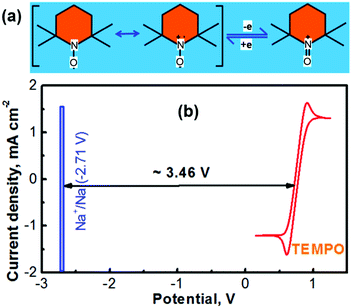
The electrochemically reversible reactions of (2,2,6,6-tetramethylpiperidin-1-yl)oxyl (TEMPO) have been well understood.24,25 As depicted in Fig. 1a, the reversible reaction between TEMPO and its oxidative species involves a one-electron charge-transfer process.26 The cationic species of TEMPO usually exists as an oxoammonium salt by combining with an anionic species in the nonaqueous electrolyte.27 According to our previous experience, propylene carbonate (PC) can serve as an ideal solvent for preparing a TEMPO catholyte (the solubility of TEMPO in PC can be up to ≈5.0 M).21 Not only a highly concentrated TEMPO solution can be accessed with the PC solvent, but also a high-concentration NaClO4 supporting electrolyte is achievable. Fig. 1b shows the cyclic voltammogram (CV) of a glassy carbon working electrode in a nonaqueous PC-solvent-based electrolyte containing 0.5 M NaClO4 and 0.1 M TEMPO. The experiments were conducted in a three-compartment cell with a lab-made Ag+/Ag nonaqueous reference electrode (RE, prepared according to our previous report18,23 and as depicted in Fig. S2 in the ESI†) and a Pt mesh counter electrode. After calibration, the Ag+/Ag RE is determined to be ∼0.45 V versus the standard hydrogen electrode (SHE).18,23 The CV profile in Fig. 1b indicates that the average reduction/oxidation potential of TEMPO is ≈0.30 V vs. the lab-made nonaqueous Ag+/Ag RE, which is ∼0.75 V vs. SHE.Battery technologies with a sodium chemistry are garnering growing attention for large-scale electrochemical energy storage owing to the merits such as the low cost and material abundance of sodium in contrast to lithium.28,29 The redox potential of sodium in a nonaqueous medium is −2.71 V vs. SHE (textbook datum, as depicted in Fig. 1b). According to the redox potentials of Na and TEMPO, an electrochemical couple of Na–TEMPO can theoretically deliver a high cell voltage of 3.46 V (Fig. 1b).
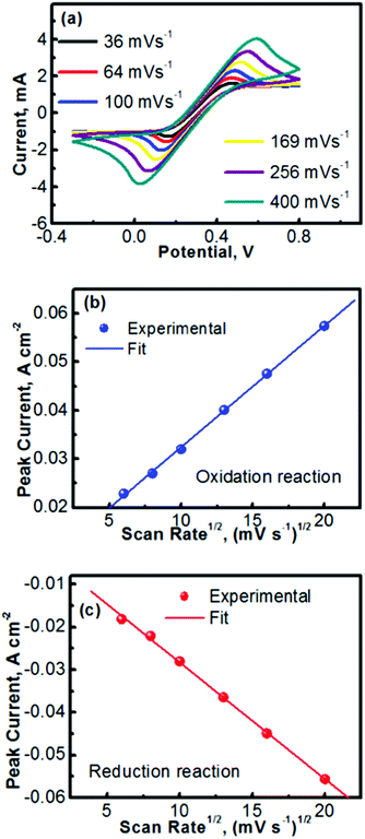
Fig. 2 summarizes the kinetics characteristics with respect to the electrochemical reactions of TEMPO and its oxidative counterpart. The CV profiles obtained at different scan rates are presented in Fig. 2a. A previous mechanistic study revealed that the electron transfer of TEMPO during the reversible reactions exhibited a rate constant of ∼0.1 cm s−1.27,30 At low scan rates, the peak separation between the oxidation and reduction waves in Fig. 2a is obvious (e.g., 0.24 V at a scan rate of 36 mV s−1), indicating the polarization of the electrode. The discrepancy between the oxidation and reduction potentials also implies that the oxidized/reduced TEMPO species may be away from equilibrium on the electrode surface. We will perform a detailed investigation in the future to further understand this phenomenon. Even with the peak separation between the oxidation and reduction reactions, the CV profiles in Fig. 2a imply that TEMPO is an ideal liquid electrode. In addition, all CV profiles exhibit a highly symmetric feature, indicating the formation of stable reduction and oxidation products during the process of reversible reactions.
Fig. 2b and c show the peak currents (ip) as a function of the square roots of scan rates (v1/2) for, respectively, the anodic and cathodic reactions of TEMPO and its oxidative counterpart (oxoammonium). A clear linear relationship is observed in both the anodic and cathodic processes, which indicates that the redox reactions are rate-determined by the mass transport of the redox species.31,32 In accord with the Randles–Sevcik equation described in Table 1,33 the diffusion coefficients of TEMPO and its oxidative species (oxoammonium cation) were analysed using the equations in Table 1 and the procedures as detailed in the Experimental section. The high diffusion coefficients of TEMPO (9.2 × 10⁻⁶ cm2 s−1) and oxoammonium cations (8.9 × 10⁻⁶ cm2 s−1), along with their excellent reversibility, reveal that TEMPO is an ideal liquid electrode for operating nonaqueous RFBs.
| I p = 2.69 × 10⁵ × A × D1/2 × n3/2 × v1/2 × C | (1) | |
| Slope = 2.69 × 10⁵ × A × D1/2 × n3/2 × C | (2) | |
| D = (Slope/(2.69 × 105 × A × n3/2× C))2 | (3) | |
| D | Diffusion coefficient | |
| C | Concentration of TEMPO | |
| n | Electron-transfer number in the reaction | |
| A | Geometric surface area of the working electrode | |
| I p | Peak current | |
| v | Scan rate | |
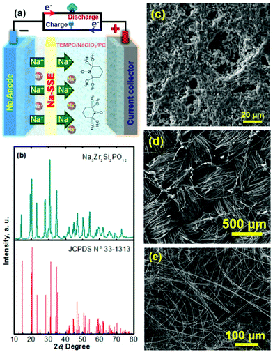
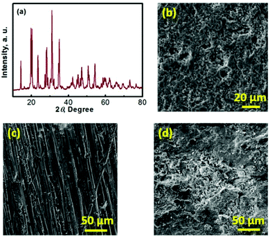
Na–TEMPO cells were assembled and tested in accord with our previously designed configuration, as schematized in Fig. 3a.17,34 A NASICON-type sodium-ion conductor, Na3Zr2Si2PO12, is incorporated to separate the Na anode and the TEMPO cathode. The Na3Zr2Si2PO12 solid-state Na+-ion electrolyte (421 Energy Inc. Ltd) exists as firm ceramic pellets, as shown in Fig. S3 in the ESI.† The purchased Na3Zr2Si2PO12 membranes have a thickness of 1.0 mm and were mechanically polished down to 0.5 mm before being used for the cell assembly. Fig. 3b and c show, respectively, an X-ray diffraction (XRD) pattern and a scanning electron microscope (SEM) image of the Na3Zr2Si2PO12 pellet. There is not a requirement for a smooth surface of the Na3Zr2Si2PO12 pellet in this study because of the facile ionic interface between the solid electrolyte and the liquid electrode.35,36 The ceramic Na3Zr2Si2PO12 pellet shows an iconic NASICON structure as reflected from the XRD pattern in Fig. 3b. The sodium-ion conductivity of the Na3Zr2Si2PO12 solid electrolyte is ∼1.0 × 10⁻³ S cm−1 at room temperature according to the information provided by the supplier.
To enhance the utilization of the liquid-phase TEMPO electrode, a highly conductive carbon cloth with a high surface area is employed as the cathode matrix. Fig. 3d shows a SEM image of the carbon cloth. To maintain a layer of liquid electrolyte between the sodium anode and the Na3Zr2Si2PO12 solid electrolyte, a piece of glass fibre is inserted in between the Na foil and the Na3Zr2Si2PO12 pellet. Fig. 3e presents a SEM image of the glass fibre. The liquid electrolyte integrated glass fibre is able to maintain a facile ionic interface.
With the PC solvent, the liquid electrolyte at the anode was prepared with 1.5 M NaClO4. The catholyte (electrode + electrolyte) was composed of 1.0 M TEMPO and 1.5 M NaClO4. The assembled Na–TEMPO cell shows an open circuit voltage of ≈3.1 V which is ∼0.36 V lower than the theoretical voltage (3.46 V as indicated in Fig. 1b) of the Na–TEMPO couple. This discrepancy might possibly be caused by the shift (relative to the standard electrode potential) of the electrochemical potential of Na metal in the nonaqueous electrolyte used in this study. Another possibility might be due to the calibration of the nonaqueous Ag/Ag+ reference electrode. As described in the Experimental section, the nonaqueous Ag/Ag+ reference electrode was calibrated against an aqueous SCE reference electrode via a salt bridge. In such a case, there might exist a junction potential between the aqueous and nonaqueous phases. We will conduct a detailed study in the future to gain a deep insight into the above issues. During the operation of the Na–TEMPO cell, the solid Na3Zr2Si2PO12 separator can prevent the liquid TEMPO catholyte from entering the surface of the Na anode. The NaClO4 salt acts as an ionic supporter to supply sodium ions to the liquid electrolytes. The electrochemical reactions at the TEMPO cathode and the sodium anode are ionically mediated by the shuttling of Na+ ions between the anode and cathode chambers through the ceramic Na3Zr2Si2PO12 solid-electrolyte separator.
The Na–TEMPO cells were operated with an excess capacity in the anode and a limited capacity in the cathode. The overall cathode capacity was maintained at 0.67 mA h (theoretical capacity) with 25 μL catholyte. The catholyte was purged with Ar before being injected into the cathode chamber. In order to evaluate the charge–discharge performance, the active catholyte material needs to be fully consumed (fully oxidized or reduced). Therefore, the cells were operated in a non-flow mode. Fig. 4a presents the charge–discharge curves of the cell cycled at various current densities. The TEMPO cathode can deliver a theoretical capacity of 171 mA h g−1, in accordance with a one-electron charge-transfer reaction. Table 2 summarizes the electrochemical cycling performance of the Na–TEMPO cell in terms of charge/discharge capacities, Coulombic efficiencies, and charge/discharge voltages. The utilization of the active TEMPO electrode is ∼80% when the cell is cycled at a relatively low current density (0.5 mA cm−2). The high working voltage (discharge voltage is >2.5 V) of the cell is attributed to the high electromotive force between the Na and TEMPO couple. With the increase of the applied current density, the cell shows remarkable polarization. By converting the gravimetric capacity to the volumetric capacity, the voltage profiles of the nonaqueous Na–TEMPO cell cycled at various current densities are presented in Fig. 4b. The volumetric capacity of the cell is ∼20 A h L−1 based on the TEMPO catholyte.
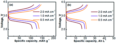 | ||
| Fig. 4 Voltage profiles of a Na–TEMPO nonaqueous cell cycled at various current densities on the basis of (a) gravimetric capacity and (b) volumetric capacity. | ||
| Current density (mA cm−2) | 0.5 | 1.0 | 2.0 |
| Charge capacity (mA h g−1) | 145.1 | 135.7 | 112.9 |
| Discharge capacity (mA h g−1) | 136.6 | 127.5 | 108.4 |
| Coulombic efficiency (%) | 94.1 | 94.0 | 96.0 |
| Charge voltage (V) | 3.26 | 3.35 | 3.45 |
| Discharge voltage (V) | 2.73 | 2.62 | 2.53 |
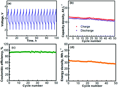
The prolonged electrochemical performance of the Na–TEMPO cell is presented in Fig. 5. The consecutive (from cycle to cycle) charge–discharge curves of the Na–TEMPO cell are displayed in Fig. 5a. The working voltage of the cell on average is at ∼2.5–2.75 V at a current density of 1.0 mA cm2. The charge and discharge capacities (volumetric) of the cell over 50 cycles are presented in Fig. 5b. Since it only needs a small amount of liquid electrolyte in the negative electrode chamber to maintain an ionic interface between sodium and the Na3Zr2Si2PO12 solid electrolyte membrane, and the liquid electrolyte at the anode is actually not involved in scaling up the storage energy, the volumetric capacity of the Na–TEMPO cell is mainly determined by the volume of the TEMPO electrode. By applying a proper approach (will be further discussed later), a facile ionic interface between the sodium anode and the Na3Zr2Si2PO12 membrane can also be possibly built without relying on a liquid electrolyte. In such a case, the Na–TEMPO cell can deliver an initial volumetric capacity of ∼19.9 A h L−1 at a current density of 1.0 mA cm2. However, with a conservative calculation by considering the influence from the anode electrolyte, the result is different from the case of only considering the volume of the catholyte. In the most conservative way assuming that all Na+ ions for the anode reaction are supplied by the anode electrolyte, it requires the consumption of 1 mole of Na+ to balance the cathodic reaction of 1 mole of TEMPO. In consideration of the solubility of NaClO4 (∼2.0 M in PC), it requires 0.5 L anode electrolyte to counter the reaction of 1.0 L of 1.0 M TEMPO. In accord with the above consideration, at a current density of 1.0 mA cm2, the Na–TEMPO cell delivers an initial volumetric capacity of ∼13 A h L−1. Then, with prolonged cycling, the capacity degrades slightly. Table 3 summarizes the capacity retention and the capacity degradation rate of the cell. Over 50 cycles, the Na–TEMPO cell retains 85.1% of its initial volumetric capacity and the capacity fades at a rate of ∼0.29% per cycle. The Coulombic efficiency of the cell during cycling is displayed in Fig. 5c. Over 50 cycles, the cell can maintain a Coulombic efficiency within the range of 91–97%. The low Coulombic efficiency implies the presence of parasitic side reactions which need to be further investigated in the future. On the other hand, the use of a large piece of sodium anode may help maintain the stable cycling of the cell even in the existence of possible side reactions. Based on the discharge capacity and the volumetric capacity, the volumetric energy density delivered by the Na–TEMPO cell is summarized in Fig. 5d. The cell can initially deliver a high energy density of ∼32 W h L−1, which slightly degrades with prolonged cycling.
| Capacity (mA h L−1) | Capacity retention (%) | Capacity fade rate (%) | |
|---|---|---|---|
| 1st cycle | 12.7 | — | — |
| 25th cycle | 12.0 | 94.5 | 0.22 |
| 50th cycle | 10.8 | 85.1 | 0.29 |
The energy density presented here was also calculated in a conservative way that had the volume of the anode electrolyte included. One of our future goals on this type of HFB includes the fabrication of a facile ionic interface between sodium metal and the Na3Zr2Si2PO12 membrane without applying a liquid electrolyte. Examples of promising approaches include (i) pressing the soft sodium metal onto the hard Na3Zr2Si2PO12 membrane and (ii) spreading the melting sodium (in a liquid phase) onto the Na3Zr2Si2PO12 membrane. Upon the success of these approaches, the energy density of such HFBs will only be determined by the volume of the catholyte.
To understand the mechanism of the capacity fade, a series of post-mortem analyses of the cycled Na–TEMPO cell were performed. Fig. 6 presents the post-mortem characterization results for each cell component of a Na–TEMPO cell upon cycling 50 times. The XRD pattern of a cycled Na3Zr2Si2PO12 membrane displayed in Fig. 6a does not show any differences from that for a fresh Na3Zr2Si2PO12 pellet (Fig. 3b). The cycled Na3Zr2Si2PO12 membrane does not show any morphological (Fig. 6b) changes as well in comparison to the fresh one (Fig. 3c). According to the information provided by the supplier, the Na3Zr2Si2PO12 ceramic electrolyte exhibits an exceptionally wide electrochemical stability window of (0–7 V, vs. Na+/Na). Based on the above facts, it is, therefore, concluded that the NASICON-type Na3Zr2Si2PO12 ceramic is both chemically and electrochemically stable under the cell operating conditions. Fig. S4 (ESI†) presents the SEM images of the glass fiber interlayer at the anode and the carbon cloth cathode matrix taken from the cycled (after 50 cycles) cell. Neither the glass fiber nor the carbon cloth shows morphological differences from the fresh samples in comparison to Fig. 3d and e, indicating the good compatibility of these two materials with the electrolyte and electrodes of the Na–TEMPO cell. Fig. 6c and d show the SEM images of a fresh Na foil and a cycled (upon 50 cycles) Na anode. There is a significant difference in the surface morphologies between the two samples. The cycled Na anode shows a severely rough feature in comparison to the pristine sample. But there is no significant Na dendrite observed. The deterioration of the anode surface is likely due to the slight leakage of the cell according to our previous experience with sodium-metal-anode batteries, which is supposed to be responsible for the capacity and energy degradation during cell cycling.37 Particularly, for the HFB designed in this study, the seal at the anode current lead (as indicated in Fig. S5 in the ESI†) tends to crack and causes an air leak with prolonged cycling of the cell. Therefore, improving the cell configuration design is one of our future efforts for the development of nonaqueous HFBs.
Although this study only demonstrates one HFB system with the Na–TEMPO couple, the nonaqueous HFB concept with the highly active sodium anode represents a versatile platform that is expected to be used for developing a broad range of nonaqueous HFBs with a variety of organic catholytes. Apart from the TEMPO cathode demonstrated in this study, many electrochemically reversible organic materials are promising candidates to be used as catholytes to couple with the sodium anode for the development of high voltage HFBs. Example catholyte candidates are Unisol Blue and its derivatives, methylphenothiazine and its derivatives, and 1,4-bis((2-(2-(2-methoxyethoxy)ethoxy)ethyl)amino)anthracene-9,10-dione (Me-TEG-DAAQ) and its derivatives.
Conclusions
By employing a sodium-ion conductive solid electrolyte, a redox half-flow cell has been developed with nonaqueous chemistries of sodium (anode) and (2,2,6,6-tetramethylpiperidin-1-yl)oxyl (TEMPO, cathode). The sodium-ion conductive Na3Zr2Si2PO12 ceramic membrane can prevent TEMPO and its oxidative product from entering the sodium anode. The internal ionic circuit of the cell is maintained by the shuttling of Na+ ions through the Na3Zr2Si2PO12 separator between the anode electrolyte and catholyte. With a liquid catholyte comprising 1.0 M TEMPO, the nonaqueous Na–TEMPO cell renders a high working voltage (>2.5 V) and delivers a remarkable volumetric energy density of ∼32 W h L−1. This research offers a new approach for the development of nonaqueous redox flow batteries with a highly active metallic anode and a single-ion solid electrolyte separator.Conflicts of interest
There are no conflicts of interest to declare.Acknowledgements
This work was supported by ExxonMobil through its membership in the University of Texas at Austin Energy Institute and the U.S. Department of Energy, Office of Basic Energy Sciences, Division of Materials Science and Engineering under award number DE-SC0005397.Notes and references
- A. Manthiram, Nat. Commun., 2020, 11, 1550 CrossRef CAS PubMed.
- Q. Schiermeier, Nature, 2016, 535, 212–213 CrossRef CAS PubMed.
- P. Fairley, Nature, 2015, 526, S102–S104 CrossRef CAS PubMed.
- W. D. Li, E. M. Erickson and A. Manthiram, Nat. Energy, 2020, 5, 26–34 CrossRef CAS.
- A. Manthiram, X. W. Yu and S. F. Wang, Nat. Rev. Mater., 2017, 2, 16103 CrossRef CAS.
- Z. G. Yang, J. L. Zhang, M. C. W. Kintner-Meyer, X. C. Lu, D. W. Choi, J. P. Lemmon and J. Liu, Chem. Rev., 2011, 111, 3577–3613 CrossRef CAS PubMed.
- G. L. Soloveichik, Chem. Rev., 2015, 115, 11533–11558 CrossRef CAS PubMed.
- C. K. Zhang, L. Y. Zhang, Y. Ding, S. S. Peng, X. L. Guo, Y. Zhao, G. H. He and G. H. Yu, Energy Storage Mater., 2018, 15, 324–350 CrossRef.
- P. Alotto, M. Guarnieri and F. Moro, Renewable Sustainable Energy Rev., 2014, 29, 325–335 CrossRef CAS.
- Q. Xu, Y. N. Ji, L. Y. Qin, P. K. Leung, F. Qiao, Y. S. Li and H. N. Su, J. Energy Storage, 2018, 16, 108–115 CrossRef.
- A. Z. Weber, M. M. Mench, J. P. Meyers, P. N. Ross, J. T. Gostick and Q. H. Liu, J. Appl. Electrochem., 2011, 41, 1137–1164 CrossRef CAS.
- R. J. Ye, D. Henkensmeier, S. J. Yoon, Z. F. Huang, D. K. Kim, Z. J. Chang, S. Kim and R. Y. Chen, J. Electrochem. Energy, 2018, 15, 010801 Search PubMed.
- K. Gong, Q. R. Fang, S. Gu, S. F. Y. Li and Y. S. Yan, Energy Environ. Sci., 2015, 8, 3515–3530 RSC.
- R. M. Darling, K. G. Gallagher, J. A. Kowalski, S. Ha and F. R. Brushett, Energy Environ. Sci., 2014, 7, 3459–3477 RSC.
- Y. Ding and G. H. Yu, Angew. Chem., Int. Ed., 2017, 56, 8614–8616 CrossRef CAS PubMed.
- Z. P. Song and H. S. Zhou, Energy Environ. Sci., 2013, 6, 2280–2301 RSC.
- X. W. Yu, M. M. Gross, S. F. Wang and A. Manthiram, Adv. Energy Mater., 2017, 7, 1602454 CrossRef.
- W. A. Y. Xingwen Yu and A. Manthiram, Small Methods, 2020, 4, 1900697 CrossRef.
- J. Winsberg, T. Hagemann, T. Janoschka, M. D. Hager and U. S. Schubert, Angew. Chem., Int. Ed., 2017, 56, 686–711 CrossRef CAS PubMed.
- S. H. Shin, S. H. Yun and S. H. Moon, RSC Adv., 2013, 3, 9095–9116 RSC.
- X. W. Yu, W. A. Yu and A. Manthiram, ACS Appl. Mater. Interfaces, 2020, 12, 48654–48661 CrossRef CAS PubMed.
- X. W. Yu, W. A. Yu and A. Manthiram, Small Methods, 2020, 4, 1900697 CrossRef CAS.
- X. W. Yu, W. A. Yu and A. Manthiram, Energy Storage Mater., 2020, 29, 266–272 CrossRef.
- J. E. Nutting, M. Rafiee and S. S. Stahl, Chem. Rev., 2018, 118, 4834–4885 CrossRef CAS PubMed.
- T. Hagemann, M. Strumpf, E. Schroter, C. Stolze, M. Grube, I. Nischang, M. D. Hager and U. S. Schubert, Chem. Mater., 2019, 31, 7987–7999 CrossRef CAS.
- J. Qu, T. Katsumata, M. Satoh, J. Wada, J. Igarashi, K. Mizoguchi and T. Masuda, Chem. – Eur. J., 2007, 13, 7965–7973 CrossRef CAS PubMed.
- Z. Li, S. Li, S. Q. Liu, K. L. Huang, D. Fang, F. C. Wang and S. Peng, Electrochem. Solid State, 2011, 14, A171–A173 CrossRef CAS.
- H. L. Pan, Y. S. Hu and L. Q. Chen, Energy Environ. Sci., 2013, 6, 2338–2360 RSC.
- A. Manthiram and X. W. Yu, Small, 2015, 11, 2108–2114 CrossRef CAS PubMed.
- K. Oyaizu, A. Hatemata, W. Choi and H. Nishide, J. Mater. Chem., 2010, 20, 5404–5410 RSC.
- M. M. Scherer, K. M. Johnson, J. C. Westall and P. G. Tratnyek, Environ. Sci. Technol., 2001, 35, 2804–2811 CrossRef CAS PubMed.
- G. J. Evans and J. R. Ling, Can. J. Chem. Eng., 2000, 78, 221–225 CrossRef CAS.
- A. M. O. Brett and C. M. A. Brett, Electrochemistry Principles, Methods and Applications, Oxford University Press, Oxford/New York, 1993 Search PubMed.
- X. W. Yu and A. Manthiram, Joule, 2017, 1, 453–462 CrossRef CAS.
- X. W. Yu and A. Manthiram, ACS Appl. Energy Mater., 2018, 1, 273–277 CrossRef CAS.
- X. W. Yu and A. Manthiram, ACS Appl. Energy Mater., 2018, 1, 2424–2428 CrossRef CAS.
- M. M. Gross and A. Manthiram, Energy Storage Mater., 2019, 19, 346–351 CrossRef.
Footnote |
| † Electronic supplementary information (ESI) available: Cell parts and the assembly of a nonaqueous HFB, schematic of the assembly of an in-house designed nonaqueous Ag+/Ag reference electrode, image of Na3Zr2Si2PO12 solid electrolyte pellets, SEM images of a cycled carbon cloth electrode matrix and a cycled glass fiber interlayer, the possible location where the leakage occurs during the operation of HFB, Fig. S1–S5. See DOI: 10.1039/d1ya00010a |
| This journal is © The Royal Society of Chemistry 2022 |

