 Open Access Article
Design of three-dimensional electrocatalytic all-in-one electrodes by leveraging electrospinning and calcination approaches†
Yaovi
Holade
 *a,
Zahra
Hagheh Kavousi
ab,
Massomeh
Ghorbanloo
 b,
Nathalie
Masquelez
a,
Sophie
Tingry
 b and
David
Cornu
 *a
*a
aInstitut Européen des Membranes, IEM, UMR 5635, Univ Montpellier, ENSCM, CNRS, 34090 Montpellier, France. E-mail: yaovi.holade@enscm.fr; david.cornu@umontpellier.fr
bDepartment of Chemistry, Faculty of Sciences, University of Zanjan, Zanjan, Iran
First published on 25th November 2022
Abstract
We report the combination of electrospinning and calcination to synthesize many free-standing electrocatalytic electrodes made of nanostructured nickel particles (active sites) and three-dimensional carbon microfibers (support). Precisely, we have used five different nickel precursors to elucidate the nitrogen origin (polyacrylonitrile or metal salts) and the impact on the electrocatalytic properties.
Electrospinning is a versatile technique that allows the generation of micro to nanoscale fibers with diverse compositions, structures and properties for uses ranging from biological to catalytic.1–6 Specifically, any metallic particle can be added on the surface and inside the fibers by using single or coaxial electrospinning setups,4–10 which offers an edge over atomic layer deposition (ALD, we do not have available precursors for all metals and multimetallic compositions),11,12 and standard calcination methods.13–18
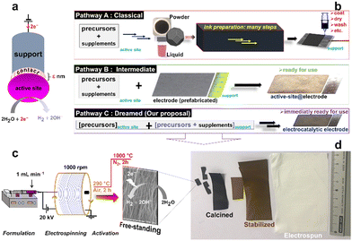
Despite the recent progress regarding the synthesis of electrospun fibers for various applications, the implementation in electrocatalysis does not fully exploit the true potential as electrode materials in which the support and the active sites are connected (Fig. 1a). Indeed, to be used in electrocatalysis, for example for electrochemically green H2 production by water electrolysis (the hydrogen or oxygen evolution reaction (HER/OER)), electrocatalysts from electrospun mats after calcination are conventionally immobilized onto electron conducting supports such as glassy carbon, metal foams, carbon paper, etc.7–9,19,20 Given the real end-use conditions, a drawback is material milling to obtain a catalytic ink (catalyst + additives (Nafion ionomer, etc.): Fig. 1b (pathway A)) and to drop-cast it onto a support, which often results in the use of high metal loading, etc. Very few studies have focused on the synthesis of free-standing electrocatalysts by combining electrospinning (to have a non-conducting mat) and calcination (to have an electron conducting support).10,21 Li et al. synthesized free-standing electrodes made of high-entropy alloy catalysts and carbon fibers with an OER overpotential of 0.407 V at 50 mA cm−2 in 0.1 M KOH.21
As shown in Fig. 1b (pathway C), electrospinning represents an alternative method to circumvent the synthetic problems of multiple steps by using the precursors of the support and the active sites as starting materials. On this basis, it should be possible to simultaneously create the support and the active sites (metal (nano)particles) to strengthen the connections between them compared to traditional methodologies (pathways A and B in Fig. 1b). It is well-known that, for supported electrocatalysts, the physicochemical interactions between the electrocatalytic (nano)particles and the support can critically affect the weight loading, surface area, activity, and stability of the electrodes under operational conditions.17 However, the systematic combination of electrospinning and calcination strategies to yield free-standing electrodes is missing (Table S1, ESI†).
Furthermore, nickel is the model electrocatalyst for HER and OER in alkaline electrolytes for sustainable H2 production.18 To synthesize Ni-based electrocatalysts, Ni(NO3)2 is the commonly used precursor. Because polyacrylonitrile (PAN) is the most used polymer for the preparation of electrospun fibers,1,22,23 the origin of the nitrogen that dopes the carbon fibers has become a debate because the few available studies are discordant.7,20 Also, the improvement of the electrocatalytic properties is sometimes attributed to the nitrogen of the pristine PAN and sometimes to that of the nitrates resulting from metal salts.7,20 So, controlled syntheses with different nickel precursors needs to be performed to elucidate not only the origin of the nitrogen but also a possible impact on the electrocatalytic properties.
Herein, with nickel as a proof of concept, we address the above challenges by using five different Ni(II) precursors during electrospinning: nitrate [Ni(NO3)2], acetate [Ni(CH3COO)2], sulphate (NiSO4), phosphate [Ni3(PO4)2] and acetylacetonate [Ni(acac)2 or Ni(C4H7COO)2]. The present study offers concrete strategies for improving the synthetic protocols of free-standing electrocatalytic electrodes made of the support and the active sites. Using a variety of physicochemical (TGA-DSC, XRD, SEM, EDX, XPS) and electrochemical (CV, LSV, EIS) characterizations, we scrutinized the physical and electrocatalytic properties.
The different steps of the synthesis are sketched in Fig. 1c (see the ESI† for the detailed description and Fig. S1 for the home-made electrospinning setup) by controlling the formation of electron-conducting materials through a two-stage calcination (Fig. 1d).
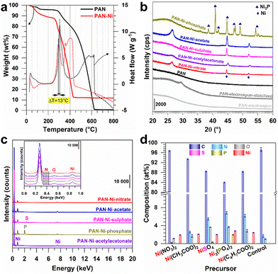
Aiming to determine a suitable temperature for the cross-linking (also referred to as the stabilization, the consolidation or the reticulation) of the constituting polymer of the electrospun mat, we performed thermogravimetric analysis (TGA) and differential scanning calorimetry (DSC) analysis of PAN and PAN–Ni. In Fig. 2a, the process below 200 °C was attributed to the removal of solvent and the surface adsorbed water molecules. The presence of nickel species decreases the reticulation (ΔT = 13 °C) similar to Fe–Co–Ni catalyst precursors when combined with PAN (peak downshift from 266 °C to 218 °C).24 The peaks found at 305 °C for PAN and at 292 °C for PAN–Ni are in agreement with the 220–300 °C range that is sufficient to trigger the processes of cyclization, dehydrogenation and oxidation, which are associated with the stabilization (Fig. S2, ESI†).7,10,19–26Fig. 2a also shows that nickel catalyses the polymer degradation where the combustion ends at 420 °C for PAN–Ni (final: 11.7 wt%) in comparison to PAN at 615 °C (final: 0.5 wt%). The final nickel content of 11.7 wt% is in agreement with our expectation of 10–12 wt% of nickel content in the final material (ESI†).
Based on these results, the electrospun mats were stabilized at 290 °C under air and then carbonized at 1000 °C under inert gas (nitrogen) to create electrical conducting carbon electrodes. Fig. S2 (ESI†) reports the different chemical processes, resulting in a colour change from white to brown and then to black as shown in Fig. 1d. We next used energy-dispersive X-ray spectroscopy (EDX) to monitor the evolution of the C/N atomic ratio during the three steps, i.e., electrospinning, stabilization and calcination. The results of Fig. S3 (ESI†) show a C/N ratio of ca. 3 for the electrospun and stabilized samples and a C/N ratio of 58 after calcination. Such results were expected because the cross-linking reaction (stabilization step) does not remove nitrogen from the PAN structure (3 carbons for 1 nitrogen), while the calcination eliminates significant amount of volatile chemical species (Fig. S2, ESI†).
We next used X-ray diffraction (XRD) to characterize the different materials derived from electrospun mats. In addition to PAN (blank), the materials were referred to as PAN–Ni-nitrate, PAN–Ni-acetate, PAN–Ni-sulphate, PAN–Ni-phosphate and PAN–Ni-acetylacetonate for the corresponding Ni(II) salts. Fig. 2b shows the obtained XRD patterns. After stabilization at 290 °C under air, a diffraction peak appears at 29.4° for (110) of the PAN fibers, and a broad peak was expected at 17° (out of range) for the PAN orthorhombic chain packing of (100).25,27 After carbonization at 1000 °C under N2, the broad peak around 26° belongs to (002) of graphite and indicates the formation of graphitic domains.22,25 PAN–Ni-X (X = nitrate, acetate, sulphate, acetylacetonate) has two peaks at 45° and 52° for the face-centred-cubic phase of Ni (JCPDS 04-0850). For PAN–Ni-phosphate, different peaks are observed at 38°, 41°, 42°, 45°, 47°, 49°, 54°, and 55° for the hexagonal Ni2P structure (JCPDS 74-1385). These results shows that the phosphate counter-anion triggers the formation of nickel phosphide, while the conditions are not sufficient to produce nickel sulphides such as Ni3S2, NiS2 and NiS with the sulphate counter-anion because many diffraction peaks would have been seen below 44°.16,28
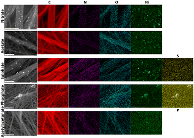
To quantify the different elements, we next combined EDX and scanning electron microscopy (SEM). Fig. 2c and d and Table S2 (ESI†) show the EDX data. Backscattered SEM images and EDX mapping are displayed in Fig. 3. As expected, the identified elements are C (0.277 keV), Ni (7.478, 8.265, 0.851, 0.762, 0.743 keV), O (0.525 keV) and N (0.392 keV) for all samples, while S (2.308, 2.464 keV) appears for PAN–Ni-sulphate and P (2.139, 2.014 keV) is characteristic of PAN–Ni-phosphate. The nickel content of 9–12 wt% confirms the theoretical expectation. The nitrogen content is N (wt%) = 0.2 ± 0.1 (PAN–Ni-nitrate), 2.6 ± 0.2 (PAN–Ni-acetate), 5.5 ± 0.3 (PAN–Ni-sulphate), 6.8 ± 0.3 (PAN–Ni-phosphate), 6.2 ± 0.3 (PAN–Ni-acetylacetonate), and 1.7 ± 0.3 (PAN). These findings allow us to decipher the debated origin of the nitrogen that dopes the carbonized carbon fibers7,20 for electrospun PAN.1,22,23 Indeed, PAN–Ni-nitrate has the lowest N content, meaning that only the nitrogen from PAN is maintained after calcination; the nitrates are mineralized and eliminated as NH3, N2 or NOx (Fig. S2, ESI†). Furthermore, the regions of high Ni and P intensities overlap for PAN–Ni-phosphate, while S is equally distributed instead of being concentrated in the Ni domains for PAN–Ni-sulphate. This proves that Ni–P particles were formed for PAN–Ni-phosphate, and for PAN–Ni-sulphate, the carbon fibers with the nickel particles have just been doped with S, which corroborates the previous XRD results. Quantitatively, P (at%) = 1.9 ± 0.1 while Ni (at%) = 2.8 ± 0.1 (initially, Ni/P = 1.5), which means that a Ni2P phase was formed (XRD), and the surplus of P comes from the doping phosphorus of the carbon fibers.
 | ||
| Fig. 3 Backscattered SEM images and the corresponding EDX mapping of the different materials derived from different precursors of Ni(+II). Scale bar = 5 μm. | ||
For the morphological characterization, SEM was performed at different magnifications and the results are gathered in Fig. S4–S9 (ESI†). Depending on the electrospun material before the calcination, the fibers have a diameter of 200–600 nm. Nickel particles have a monodispersed size for PAN–Ni-acetylacetonate and PAN–Ni-acetate. PAN–Ni-nitrate, PAN–Ni-sulphate and PAN–Ni-phosphate have a heterogeneous size distribution, which means that the synthesis condition needs further optimization. Taken together, these characterizations show that the nature of the counter-anion dramatically affects the structure, the composition and likely the physicochemical properties of the materials derived from electrospun mats after calcination.
Having demonstrated that electrospun PAN–Ni mats based on different Ni (II) precursors produce diverse materials, we next sought to interrogate the electrochemical properties. We were interested in knowing whether the electron transfer ability is affected. To this end, as aforementioned (Fig. 1), we took advantage of the free-standing nature to prepare the working electrode by cutting the parent material into an L-shape of 0.5 cm high and 0.5 cm width (geometric area of 0.5 cm2, not taking into account the 3D structure) and enough space on the top for an electrical connection with a gold wire.
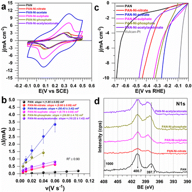
In 0.5 M KNO3 + 5 mM K3[Fe(CN)6], the objective was to evaluate the reversibility of the redox probe Fe(CN)63−/Fe(CN)64− and to determine the uncompensated ohmic resistance (RΩ). In 1 M KOH, the objective was to evaluate the electrochemically active surface area (ECSA), RΩ and HER/OER efficiencies. RΩ resulted from EIS (electrochemical impedance spectroscopy, Fig. S10, ESI†) and includes contribution from the connections, the electrolyte, and the working electrode. In neutral media, RΩ(Ω) = 15, 30, 17, 27, 40, and 32 for 0.5 cm2 electrodes derived from PAN, PAN–Ni-nitrate, PAN–Ni-acetate, PAN–Ni-sulphate, PAN–Ni-phosphate, and PAN–Ni-acetylacetonate, respectively. In addition, in 1 M KOH electrolyte, RΩ(Ω) = 8, 28, 7, 10, 50, and 19 for the same order. The higher value for PAN–Ni-phosphate could be explained by the fact that nickel phosphides have a lower electrical conductivity than pure nickel. Overall, these results suggest that there is an additional ohmic resistance from the electrocatalytic material and one can observe from Fig. 4a that the peak-to-peak potential difference of the reversibility was impacted (a large value is indicative of a low charge transfer rate). Furthermore, the determined double-layer capacitances (Fig. 4b and Fig. S11, ESI†) were Cdl = 1.8 ± 0.1, 9.8 ± 0.7, 50.4 ± 3.4, 8.8 ± 0.8, 24.7 ± 4.7, and 20.2 ± 1.4 mF for PAN, PAN–Ni-nitrate, PAN–Ni-acetate, PAN–Ni-sulphate, PAN–Ni-phosphate, and PAN–Ni-acetylacetonate, respectively. So, PAN–Ni-nitrate and PAN–Ni-sulphate have the lowest ECSA (Fig. S12, ESI†); ECSA = Cdl/Cs; Cs = 40 μF cm−2 (see ESI†). To evaluate whether this discrepancy in ECSA affects the electrocatalytic performance, we tested the HER (Fig. 4c and S13, ESI†) and OER (Fig. S14, ESI†). We finally compare these with the reported relevant electrocatalysts, synthesized by combining electrospinning and calcination (Table S1, ESI†). The performance trend from the linear sweep voltammetry (LSV) method for HER was PAN–Ni-acetate > PAN–Ni-phosphate > PAN–Ni-sulphate > PAN–Ni-nitrate > PAN–Ni-acetylacetonate. It is clear that the initial presence of nitrogen in Ni(NO3)2 does not lead to a better electrocatalytic performance. At 10 mA cm−2, the lowest HER overpotential of 0.26 V and OER overpotential of 0.37 V for PAN–Ni-acetate (the best catalyst) is analogous to the literature where catalytic inks were prepared.7–9,19,20 We point out that the present results are only preliminary results since during stability tests by chronoamperometry, the electrodes failed because of the gas accumulation in the 3D material which led to the electrodes swelling and then their delamination. Thus, these electrodes must be reinforced before considering their real use.
We finally used X-ray photoelectron spectroscopy (XPS) for the surface analysis. Fig. 4d shows the high-resolution spectrum of N 1s, those of C 1s and Ni 2p are reported in Fig. S15 (ESI†). The atomic composition in Fig. S16 and S17 (ESI†) is consistent with EDX analysis and confirms that Ni(NO3)2 does not lead to a higher nitrogen doping. The graphitic nitrogen is the main component (33–50%). Based on our previous detailed XPS analysis of Ni 2p,16 the binding energy shift of 1.5 eV in Fig. S15b (ESI†) suggests that the nature of Ni(II) precursor during the initial step of electrospinning subsequently affects the interaction between the Ni particles and the nitrogen doped carbon fibers.
In conclusion, we have demonstrated how controlled electrospinning and thermal treatments can result in the design of centimeter scale electrocatalytic electrodes made of nanostructured nickel particles embedded in a 3D network of nitrogen-doped carbon fibers. The nature of the nickel(II) precursor during the electrospinning affects the structure, composition and properties of the calcined materials. We found different electron transfer and electrocatalytic properties as revealed by the Fe(CN)63−/Fe(CN)64− redox probe and the electrocatalytic hydrogen/oxygen evolution reaction (HER/OER). However, the gas evolution provokes electrode swelling so that the electrodes have a lower stability. Nevertheless, our findings can be transferred to other metals of interest to synthesize free-standing electrocatalytic electrodes after optimizations.
This work was funded by LabEx CheMISyst (ANR-10-LABX-05-01) and by the CNRS Energy unit (PEPS19-ELECTROFUEL). We thank D. Cot and B. Rebiere for the SEM-EDX assistance.
Conflicts of interest
There are no conflicts to declare.Notes and references
- J. Xue, T. Wu, Y. Dai and Y. Xia, Chem. Rev., 2019, 119, 5298–5415 CrossRef CAS.
- S. Cavaliere, S. Subianto, I. Savych, D. J. Jones and J. Roziere, Energy Environ. Sci., 2011, 4, 4761–4785 RSC.
- A. Saleh, E. Marhuenda, C. Fabre, Z. Hassani, J. D. Weille, H. Boukhaddaoui, S. Guelfi, I. L. Maldonado, J.-P. Hugnot, H. Duffau, L. Bauchet, D. Cornu and N. Bakalara, Sci. Rep., 2019, 9, 14612 CrossRef.
- J. Hao, Z. Zhuang, J. Hao, K. Cao, Y. Hu, W. Wu, S. Lu, C. Wang, N. Zhang and D. Wang, ACS Nano, 2022, 16, 3251–3263 CrossRef CAS PubMed.
- J. Hao, Z. Zhuang, K. Cao, G. Gao, C. Wang, F. Lai, S. Lu, P. Ma, W. Dong and T. Liu, Nat. Commun., 2022, 13, 1–13 Search PubMed.
- Y. Wen, Z. Zhuang, H. Zhu, J. Hao, K. Chu, F. Lai, W. Zong, C. Wang, P. Ma and W. Dong, Adv. Energy Mater., 2021, 11, 2102138 CrossRef CAS.
- X. Wang, Y. Li, T. Jin, J. Meng, L. Jiao, M. Zhu and J. Chen, Nano Lett., 2017, 17, 7989–7994 CrossRef CAS PubMed.
- J. Li, S. Sun, Y. Yang, Y. Dai, B. Zhang and L. Feng, Chem. Commun., 2022, 58, 9552–9555 RSC.
- F. Qiang, J. Feng, H. Wang, J. Yu, J. Shi, M. Huang, Z. Shi, S. Liu, P. Li and L. Dong, ACS Catal., 2022, 12, 4002–4015 CrossRef CAS.
- A. Both Engel, M. Bechelany, O. Fontaine, A. Cherifi, D. Cornu and S. Tingry, ChemElectroChem, 2016, 3, 629–637 CrossRef CAS.
- N. Cheng, Y. Shao, J. Liu and X. Sun, Nano Energy, 2016, 29, 220–242 CrossRef CAS.
- M. Weber, N. Tuleushova, J. Zgheib, C. Lamboux, I. Iatsunskyi, E. Coy, V. Flaud, S. Tingry, D. Cornu, P. Miele, M. Bechelany and Y. Holade, Appl. Catal., B, 2019, 257, 117917 CrossRef CAS.
- X. Chen, S. Zhang, X. Qian, Z. Liang, Y. Xue, X. Zhang, J. Tian, Y. Han and M. Shao, Appl. Catal., B, 2022, 310, 121277 CrossRef CAS.
- X. Chen, C. Ma, Z. Tan, X. Wang, X. Qian, X. Zhang, J. Tian, S. Yan and M. Shao, Chem. Eng. J., 2022, 433, 134504 CrossRef CAS.
- C.-H. Yang, F. Nosheen and Z.-C. Zhang, Rare Met., 2021, 40, 1412–1430 CrossRef CAS.
- R. Djara, Y. Holade, A. Merzouki, M.-A. Lacour, N. Masquelez, V. Flaud, D. Cot, B. Rebiere, A. van der Lee, J. Cambedouzou, P. Huguet, S. Tingry and D. Cornu, Front. Chem., 2020, 8, 385 CrossRef CAS PubMed.
- H. P. Tran, H. N. Nong, H.-S. Oh, M. Klingenhof, M. Kroschel, B. Paul, J. Hübner, D. Teschner and P. Strasser, Chem. Mater., 2022, 34, 9350–9363 CrossRef CAS.
- M. Chatenet, B. G. Pollet, D. R. Dekel, F. Dionigi, J. Deseure, P. Millet, R. D. Braatz, M. Z. Bazant, M. Eikerling and I. Staffell, Chem. Soc. Rev., 2022, 51, 4583–4762 RSC.
- M. Li, H. Wang, W. Zhu, W. Li, C. Wang and X. Lu, Adv. Sci., 2020, 7, 1901833 CrossRef CAS.
- Y. Zhao, J. Zhang, K. Li, Z. Ao, C. Wang, H. Liu, K. Sun and G. Wang, J. Mater. Chem. A, 2016, 4, 12818–12824 RSC.
- H. Li, H. Zhu, S. Sun, J. Hao, Z. Zhu, F. Xu, S. Lu, F. Duan and M. Du, Chem. Commun., 2021, 57, 10027–10030 RSC.
- B. Zhang, Y. Yu, Z.-L. Xu, S. Abouali, M. Akbari, Y.-B. He, F. Kang and J.-K. Kim, Adv. Energy Mater., 2014, 4, 1301448 CrossRef.
- K. Badii, J. S. Church, G. Golkarnarenji, M. Naebe and H. Khayyam, Polym. Degrad. Stab., 2016, 131, 53–61 CrossRef CAS.
- C. Tekmen, Y. Tsunekawa and H. Nakanishi, J. Mater. Process. Technol., 2010, 210, 451–455 CrossRef CAS.
- M. Wu, Q. Wang, K. Li, Y. Wu and H. Liu, Polym. Degrad. Stab., 2012, 97, 1511–1519 CrossRef CAS.
- M. Coronas, Y. Holade and D. Cornu, Materials, 2022, 15, 4336 CrossRef CAS PubMed.
- H. F. Moafi, A. Fallah Shojaie and M. Ali Zanjanchi, J. Chil. Chem. Soc., 2011, 56, 610–615 CrossRef CAS.
- N. Jiang, Q. Tang, M. Sheng, B. You, D.-E. Jiang and Y. Sun, Catal. Sci. Technol., 2016, 6, 1077–1084 RSC.
Footnote |
| † Electronic supplementary information (ESI) available: Experimental details; extended characterization. See DOI: https://doi.org/10.1039/d2cc05873a |
| This journal is © The Royal Society of Chemistry 2023 |


