 Open Access Article
Equilibrium unconstrained low-temperature CO2 conversion on doped gallium oxides by chemical looping†
Keke
Kang
,
Sota
Kakihara
,
Takuma
Higo
 ,
Hiroshi
Sampei
 ,
Koki
Saegusa
and
Yasushi
Sekine
 *
*
Department of Applied Chemistry, Waseda University, 3-4-1, Okubo, Shinjuku, Tokyo, 169-8555, Japan. E-mail: ysekine@waseda.jp
First published on 21st August 2023
Abstract
Reverse water gas shift (RWGS) can convert CO2 into CO by using renewable hydrogen. However, this important reaction is endothermic and equilibrium constrained, and thus traditionally performed at 900 K or higher temperatures using solid catalysts. In this work, we found that RWGS can be carried out at low temperatures without equilibrium constraints using a redox method called chemical looping (CL), which uses the reduction and oxidation of solid oxide surfaces. When using our developed MGa2Ox (M = Ni, Cu, Co) materials, the reaction can proceed with almost 100% CO2 conversion even at temperatures as low as 673 K. This allows RWGS to proceed without equilibrium constraints at low temperatures and greatly decreases the cost for the separation of unreacted CO2 and produced CO. Our novel gallium-based material is the first material that can achieve high conversion rates at low temperatures in reverse water gas shift using chemical looping (RWGS-CL). Ni outperformed Cu and Co as a dopant, and the redox mechanism of NiGa2Ox is a phase change due to the redox of Ga during the RWGS-CL process. This major finding is a big step forward for the effective utilization of CO2 in the future.
As a greenhouse gas, carbon dioxide (CO2) is emitted excessively from fossil fuel combustion, causing severe environmental difficulties.1,2 Therefore, to achieve carbon neutrality, developing CO2 capture and utilization (CCU) technologies that can accommodate sustainable recycling3–6 is pivotally important. The reverse water gas shift (RWGS) reaction (eqn (1)) is a promising catalytic method to achieve “CO2-to-CO” conversion using renewable H2 as a reductant. The produced CO can be used flexibly for both methanol (MeOH) synthesis and downstream Fischer–Tropsch (F–T) processes to produce various liquid chemicals and fuels.7,8 However, conventional RWGS is an endothermic and reversible reaction associated with shortcomings such as high operating temperature, equilibrium constraints, unwanted side reactions of methanation (eqn (2) and (3)) and complicated separation of gaseous products.3
| H2 + CO2 ↔ H2O + CO ΔrHθ (298 K) = 41.2 kJ mol−1 | (1) |
| CO2 + 4H2 ↔ CH4 + 2H2O ΔrHθ (298 K) = −165.0 kJ mol−1 | (2) |
| CO + 3H2 ↔ CH4 + H2O ΔrHθ (298 K) = −206.2 kJ mol−1 | (3) |
| Reduction step: MOx + δH2 → MOx−δ + δH2O | (4) |
| Oxidation step: MOx−δ + δCO2 ↔ MOx + δCO | (5) |
The redox performance of OSMs is crucially important for RWGS-CL. Recently, much progress has been made to develop OSMs with excellent RWGS-CL performance, such as perovskite-structured oxides,8,11–18 spinel-structured oxides,19–21 Fe-based oxides,19–22 and In-based oxides.23,24 Although experimental conditions such as H2 or CO2 feed gas concentrations and detection methods are not all the same in those studies, a recent report described that Co–In oxide showed the best CO2 splitting rate of 0.28 mmol min−1 g−1 and a redox amount of 3.25 mmol g−1 at 773 K in comparison to other reported materials.24 However, in practice, the low CO2 equilibrium conversion of the oxidation step leads to a low concentration of the produced CO (the ratio of (CO/CO + CO2)), increasing the cost of separating CO from CO2 in the overall route with RWGS-CL (highlighted red box in Fig. S1, ESI†). Therefore, it is necessary to find proper OSMs that can make the oxidation step proceed forward rapidly even with a high CO concentration. Nevertheless, no study reported to date has particularly addressed this matter. Reportedly, the CO2 oxidation step can proceed forward on Co–In2O3 with a 70–80% concentration of CO in the medium temperature region, but CO was not introduced simultaneously when evaluating the RWGS-CL performance.24
In this work, novel MGa2O4 (M = Ni, Cu, Co) spinel structured oxides were developed as OSMs with almost 100% CO2 conversion even at lower temperature and Ni outperforms Cu and Co as a dopant in the redox amount and CO2 splitting rate. The method for measuring the maximum CO2 conversion of the oxidation step, the procedure for the RWGS-CL cycling test and the related definitions for evaluating the performance are also described in the ESI† text.
To elucidate the reaction mechanisms of the NiGa2Ox material, powder X-ray diffraction (XRD), transmission electron microscopy with energy-dispersive X-ray spectroscopy (STEM-EDX), Brunauer–Emmett–Teller (BET) measurement and in situ X-ray absorption fine structure (in situ XAFS) were conducted to characterize the structural features. Moreover, the redox behaviors of the MGa2Ox (M = Ni, Cu, Co) oxides were characterized by H2 temperature-programmed reduction (H2-TPR) and CO2 temperature-programmed oxidation (CO2-TPO). Kinetics analysis was also conducted to elucidate the oxidation behavior of NiGa2Ox with 90% CO–10% CO2 when using the Ozawa–Flynn–Wall (OFW) method (details in the ESI†).
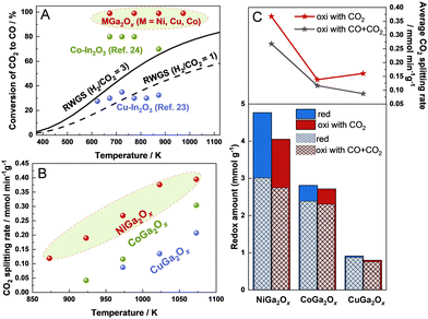
Comparison between the maximum CO2 conversion of MGa2Ox (M = Ni, Cu, Co) and earlier reported In-based materials for RWGS-CL and the equilibrium conversion of conventional RWGS is presented in Fig. 1A, and the experimentally obtained data for MGa2Ox are presented, respectively, in the ESI† text and in Fig. S2–S5 (ESI†). Ga metal is known to have a very low melting point (302.8 K) on its own when reduced, but in this study Ga always remained in a composite (alloyed) state with other metals, and no melting or volatilization was observed before or after H2 reduction. Actually, Cu–In2O3 and Co–In2O3 were both reported to show superior fast kinetics at medium temperatures. However, Cu–In2O3 showed no advantage for CO2 conversion compared with the conventional RWGS.25 Although Co–In2O3 displayed a maximum CO2 conversion of 70–80% in the medium temperature region, which is higher than that of conventional RWGS, there is some room for improving it to conserve energy and decrease costs. Regarding MGa2Ox (M = Ni, Cu, Co), they showed a maximum CO2 conversion of 99% at temperatures in the range of 673–973 K, which is much higher than the equilibrium conversion of conventional RWGS and the materials reported earlier. This result indicates MGa2Ox (M = Ni, Cu, Co) as promising RWGS-CL materials with superior thermodynamical advantages.
The redox amounts and CO2 splitting rates of NiGa2Ox and CuGa2Ox were all measured after sufficient H2 pretreatment at 973 K until the following cycles became stable, but it is difficult for CoGa2Ox to reach a stable state, even when pretreated at a higher temperature for its low reduction rate, as confirmed by the combination of redox amounts and XRD (related descriptions are presented in Fig. S6 and S7, ESI†). Deeper pre-reduction at high temperatures will aggregate the particles and shrink the surface area (the results of BET are presented in Table S1, ESI†), consequently deteriorating the RWGS-CL performance. Therefore, we infer CoGa2Ox as an unsuitable material for RWGS-CL. However, the performance data of CoGa2Ox without reaching a stable state will still be presented as a comparison for the following discussion. The CO2 splitting rates of MGa2Ox (M = Ni, Cu, Co) with 90% CO–10% CO2 at different temperatures are shown in Fig. 1B. NiGa2Ox shows high average CO2 splitting rates of 0.12, 0.19, 0.27, 0.38, and 0.39 mmol min−1 g−1 at 873, 923, 973, 1023, and 1073 K, respectively, even under a 90% concentration of CO, which is markedly higher than those of CoGa2Ox and CuGa2Ox.
The CO2 splitting rates and redox amounts of MGa2Ox (M = Ni, Cu, Co) at 973 K under different oxidation conditions (10% CO2; 90% CO–10% CO2) are presented in Fig. 1C. Generally, oxidation with CO + CO2 decreases both the redox amounts and the CO2 splitting rate compared with oxidation with only CO2 because of the backward progress of the reverse reaction. Ni is a better dopant than Co and Cu in terms of the redox amount and CO2 splitting rate under both CO2 and CO + CO2 oxidation conditions. The experimental results (Fig. S8 and ESI† text) indicate no by-product formation and negligible carbon deposition using a fixed bed reactor equipped with a quadrupole mass spectrometer (Q-MS), which show the reliability and repeatability of our method. Moreover, comparisons of the CO2 splitting rates and CO yields of the OSMs for RWGS-CL in the present work (with 10% CO2) and in the literature are presented in Fig. S9 (ESI†). Actually, NiGa2Ox shows a relatively high CO2 splitting rate and CO yield compared to those of the other reported OSMs.8,11,13,16,19–21,26–28 In summary, NiGa2Ox showed high potential for RWGS-CL and was therefore selected for further study. The stability results of NiGa2Ox over 10 cycles at 973 K are shown in Fig. S10 (ESI†), exhibiting a slow decrease in the oxidation amounts and CO2 splitting rates during cycling, which is partially attributable to the deep pre-reduction and repetitive cycles leading to partial shrinkage of the surface area of the material. The STEM-EDS results in Fig. S11 and BET results in Table S1 confirm the structure stability even after 10 cycles of reaction (details in the ESI†).
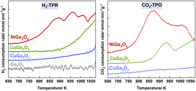
H2-TPR measurements were conducted on different metal oxide samples for RWGS-CL analysis (Fig. 2A). Ga2O3 shows almost no reduction in the tested temperature range, the dopants of Ni, Co and Cu improve the reducibility of Ga2O3 to a different extent. NiGa2Ox exhibited a significantly higher H2 consumption amount which started at a much lower temperature compared to CoGa2Ox or CuGa2Ox, indicating the dopant of Ni outperforms Cu or Co in reducibility. Similarly, CO2-TPO measurements (Fig. 2B) confirmed that the Ni dopant also outperforms Cu or Co in the oxidation ability. NiGa2Ox also shows a much higher surface area both after reduction and after oxidation than CoGa2Ox or CuGa2Ox according to the BET results (Table S1, ESI†). A larger surface area provides more reaction sites, allowing more reactant molecules to participate in the reaction simultaneously, leading to a better reaction rate for NiGa2Ox. Moreover, the results of density functional theory (DFT) calculations show that the Ni-doping material displays a better CO adsorption ability than the other two, which is beneficial for Ni outperforming Cu and Co as a dopant (details in Fig. S12–S14 and Table S2 and ESI† text).
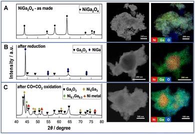
Structural and electronic properties were investigated using XRD, STEM-EDX, BET, and in situ XAFS. From the XRD spectra in Fig. 3A (left), the as-prepared sample shows only peaks of the NiGa2O4 spinel, manifesting the successful preparation of the target material. From the STEM-EDX images of the as-prepared NiGa2O4 (Fig. 3A (right), details in Fig. S15, ESI†), tens of nanometers of polycrystalline particles are observed. The Ni and Ga species are all dispersed uniformly. Regarding the reduced NiGa2Ox, the XRD profile exhibits peaks for the NiGa alloy and Ga2O3. Also, STEM-EDX images (Fig. 3B (right)) show aggregated Ni species during uniform dispersion of the Ga species. Moreover, the surface area is markedly reduced after the reduction because of the alloy formation. These findings manifest that all NiO and part of Ga2O3 are reduced to form the NiGa alloy, thus leaving part of the Ga2O3 unreduced. For the CO + CO2 oxidized NiGa2Ox, polycrystalline particles with a size of tens of nanometers are observed from STEM images, indicating that the particles will aggregate to larger ones after reduction and reoxidation by CO + CO2 processing, thereby leading to a decreased surface area as shown in Table S1 (ESI†). Moreover, the XRD patterns display the peaks of Ga2O3, Ni metal and Ni–Ga alloy (Ni5Ga3 and Ni0.7Ga0.3). STEM-EDX images (Fig. 3C (right)) show consistent results of the partial aggregation of Ni species to form the Ni–Ga alloy during uniform dispersion of Ga species and the remaining part of Ni species. These illustrate that only part of the Ga species in the NiGa alloy are re-oxidized to Ga2O3 by CO + CO2, whereas Ni species remain in a metallic state, acting as a part of the alloy or an individual element throughout the RWGS-CL process. Additionally, from the XRD results of the CO2-only oxidized NiGa2Ox shown in Fig. S16 (ESI†), only Ni metal and Ga2O3 peaks were observed, with no peaks of the Ni–Ga alloy compared with the XRD results of CO + CO2 oxidized NiGa2Ox. This finding illustrates that the presence of CO influences the amount of the Ni–Ga alloy which can be re-oxidized in the oxidation step.
 | ||
| Fig. 3 XRD profiles (left) and STEM-EDX images (right) of NiGa2Ox (A) as-prepared, (B) after reduction and (C) after CO + CO2 oxidation. | ||
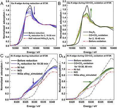
The in situ XAFS results of NiGa2Ox at 973 K are presented in Fig. 4. The XANES spectra on the Ga K-edge shift negatively to the spectrum of the pre-prepared half-reduced NiGa2O4 sample during the reduction and shift positively to the Ga2O3 spectrum during the CO + CO2 reoxidation (Fig. 4A and B). These regular changes on the Ga K-edge during the RWGS-CL process provide evidence of the successful redox cycle of gallium. From the spectra of NiGa2Ox during CO2 re-oxidation shown in Fig. S17A (ESI†), it is apparent that the spectra shift faster and finally become closer to that of Ga2O3 than that during CO + CO2 reoxidation, indicating that the presence of CO in the oxidation step can be expected to restrain the progress of the oxidation of Ga.
 | ||
| Fig. 4 XANES spectra of NiGa2Ox during (A) H2 reduction and (B) CO + CO2 oxidation on the Ga K-edge, and (C) H2 reduction and (D) CO + CO2 oxidation on the Ni K-edge. | ||
From another perspective, Ni K-edge XANES spectra shift negatively toward the direction of the Ni spectrum with a slightly different peak shape during reduction (Fig. 4C) and very similar peak shapes to the simulated NiGa alloy spectrum obtained by calculation (calculation details in the ESI† text), thereby manifesting the formation of the NiGa alloy, except for Ni metal. During CO + CO2 reoxidation, the spectra shift slowly to the Ni spectrum (Fig. 4D), manifesting that Ni metals are partially decomposed from the Ni–Ga alloy. Furthermore, the peak shapes are very different from those of NiO, indicating that no NiO was produced during the oxidation. Regarding the spectra of NiGa2Ox during CO2 reoxidation in Fig. S17B (ESI†), the spectra shift faster and finally become closer to the Ni spectrum than those during CO + CO2 reoxidation. This manifests that the presence of CO in the oxidation step can be expected to restrain the degree of decomposition of the Ni–Ga alloy.
Based on the analyses of structural and electronic properties, the proposed redox mechanism of NiGa2Ox during the RWGS-CL process in the presence of a high concentration of CO is shown in Fig. S18 (ESI†). Specifically, the Ni–Ga alloy is formed on Ga2O3 by H2 reduction, with formation of oxygen vacancies. Then CO2 is adsorbed and dissociated on the Ni–Ga alloy with progress of the oxidation step, thereby re-filling the oxygen vacancies. It is worth noting that the presence of CO in the oxidation step influences the NiGa2Ox performance by restraining the oxygen re-filling, leading to smaller amounts of Ga species for the key phase-change process.
In situ XAFS measurements were performed at the beamline BL14B2 of SPring-8 (Proposal No. 2022B1775). MEXT Project (Grant No. JPMXS0440500022; JPMXS0440500023), supercomputer system at Hokkaido University (Sapporo, Japan) and China Scholarship Council (Grant No. 202104910057) are acknowledged.
Conflicts of interest
The authors have no conflicts of interest.References
- IPCC AR6: Climate Change 2021.
- K. Tucki, O. Orynycz and M. Mitoraj-Wojtanek, Energies, 2020, 13, 4127 CrossRef CAS
.
- J. Artz, T. E. Müller, K. Thenert, J. Kleinekorte, R. Meys, A. Sternberg, A. Bardow and W. Leitner, Chem. Rev., 2018, 118, 434–504 CrossRef CAS PubMed
.
- F. V. Vázquez, J. Koponen, V. Ruuskanen, C. Bajamundi, A. Kosonen, P. Simell, J. Ahola, C. Frilund, J. Elfving, M. Reinikainen, N. Heikkinen, J. Kauppinen and P. Piermartini, J. CO2 Util., 2018, 28, 235–246 CrossRef
.
- C. Hepburn, E. Adlen, J. Beddington, E. A. Carter, S. Fuss, N. Mac Dowell, J. C. Minx, P. Smith and C. K. Williams, Nature, 2019, 575, 87–97 CrossRef CAS PubMed
.
- H.-H. Qiu and L.-G. Liu, Energies, 2018, 11, 1103 CrossRef
.
- G. Centi, E. A. Quadrelli and S. Perathoner, Energy Environ. Sci., 2013, 6, 1711–1731 RSC
.
- D. Maiti, B. J. Hare, Y. A. Daza, A. E. Ramos, J. N. Kuhn and V. R. Bhethanabotla, Energy Environ. Sci., 2018, 11, 648–659 RSC
.
- M. Wenzel, L. Rihko-Struckmann and K. Sundmacher, AIChE J., 2017, 63, 15–22 CrossRef CAS
.
- S. Y. Tee, K. Y. Win, W. S. Teo, L.-D. Koh, S. Liu, C. P. Teng and M.-Y. Han, Adv. Sci., 2017, 4, 1600337 CrossRef PubMed
.
- Y. A. Daza, D. Maiti, R. A. Kent, V. R. Bhethanabotla and J. N. Kuhn, Catal. Today, 2015, 258, 691–698 CrossRef CAS
.
- B. J. Hare, D. Maiti, S. Ramani, A. E. Ramos, V. R. Bhethanabotla and J. N. Kuhn, Catal. Today, 2019, 323, 225–232 CrossRef CAS
.
- A. E. Ramos, D. Maiti, Y. A. Daza, J. N. Kuhn and V. R. Bhethanabotla, Catal. Today, 2019, 338, 52–59 CrossRef CAS
.
- J. C. Brower, B. J. Hare, V. R. Bhethanabotla and J. N. Kuhn, ChemCatChem, 2020, 12, 6317–6328 CrossRef CAS
.
- Y. A. Daza, R. A. Kent, M. M. Yung and J. N. Kuhn, Ind. Eng. Chem. Res., 2014, 53, 5828–5837 CrossRef CAS
.
- A. Jo, Y. Kim, H. S. Lim, M. Lee, D. Kang and J. W. Lee, J. CO2 Util., 2022, 56, 101845 CrossRef CAS
.
- H. Z. Shi, V. R. Bhethanabotla and J. N. Kuhn, J. CO2 Util., 2021, 51, 101638 CrossRef CAS
.
- Y. A. Daza, D. Maiti, B. J. Hare, V. R. Bhethanabotla and J. N. Kuhn, Surf. Sci., 2016, 648, 92–99 CrossRef CAS
.
- J. Rojas, E. Sun, G. Wan, J. Oh, R. Randall, V. Haribal, I.-H. Jung, R. Gupta and A. Majumdar, ACS Sustainable Chem. Eng., 2022, 10, 12252–12261 CrossRef CAS
.
- L. Ma, Y. Qiu, M. Li, D. Cui, S. Zhang, D. Zeng and R. Xiao, Ind. Eng. Chem. Res., 2020, 59, 6924–6930 CrossRef CAS
.
- Y. Qiu, L. Ma, D. Zeng, M. Li, D. Cui, Y. Lv, S. Zhang and R. Xiao, J. Energy Chem., 2020, 46, 123–132 CrossRef
.
- D. Zeng, Y. Qiu, L. Ma, M. Li, D. Cui, S. Zhang and R. Xiao, Environ. Sci. Technol., 2020, 54, 12467–12475 CrossRef CAS PubMed
.
- J. I. Makiura, T. Higo, Y. Kurosawa, K. Murakami, S. Ogo, H. Tsuneki, Y. Hashimoto, Y. Sato and Y. Sekine, Chem. Sci., 2020, 12, 2108–2113 RSC
.
- J. I. Makiura, S. Kakihara, T. Higo, N. Ito, Y. Hirano and Y. Sekine, Chem. Commun., 2022, 58, 4837–4840 RSC
.
- X. Cui and S. K. Kær, Ind. Eng. Chem. Res., 2019, 58, 10559–10569 CrossRef CAS
.
- F. J. Pomiro, G. G. Fouga, A. E. Bohé and G. De Micco, J. Alloys Compd., 2023, 938, 168671 CrossRef CAS
.
- H. S. Lim, Y. Kim, D. Kang, M. Lee, A. Jo and J. W. Lee, ACS Catal., 2021, 11, 12220–12231 CrossRef CAS
.
- H. Shi, V. R. Bhethanabotla and J. N. Kuhn, J. Ind. Eng. Chem., 2023, 118, 44–52 CrossRef CAS
.
Footnote |
| † Electronic supplementary information (ESI) available. See DOI: https://doi.org/10.1039/d3cc02399k |
| This journal is © The Royal Society of Chemistry 2023 |


