 Open Access Article
Creative Commons Attribution 3.0 Unported Licence
Spark plasma sintered catalytic nickel–copper alloy and carbon nanotube electrodes for the hydrogen evolution reaction†
Jean-Félix
Boué
ab,
Cédric
Espinet
a,
Simon
Amigues
a,
David
Mesguich
b,
David
Cornu
bc,
Yaovi
Holade
 *ac,
Julien
Cambedouzou
 *ac and
Christophe
Laurent
*b
aInstitut Institut Européen des Membranes, IEM, UMR 5635, Univ Montpellier, ENSCM, CNRS, Montpellier 34090, France. E-mail: yaovi.holade@enscm.fr; julien.cambedouzou@enscm.fr
bCIRIMAT, Université Toulouse 3 Paul Sabatier, CNRS, Université de Toulouse, 118 Route de Narbonne, Toulouse cedex 9 31062, France. E-mail: christophe.laurent@univ-tlse3.fr
cFrench Research Network on Hydrogen (FRH2), Research Federation No. 2044 CNRS, BP 32229, Nantes CEDEX 3 44322, France Web: https://frh2.cnrs.fr/
First published on 23rd October 2023
Abstract
We report the proof-of-concept of spark plasma sintered (SPS) consolidated mesoporous composite catalytic electrodes based on nickel–copper alloys and carbon nanotubes for the electrocatalytic hydrogen evolution reaction (HER) in alkaline media. The optimized electrode (203 m2 g−1, 5 wt% Ni75Cu25) operated at −0.1 A cm−2 (current of −0.15 A) for 24 h with a stable overpotential of about 0.3 V. This newly described freestanding SPS approach allows the rational control of specific surface area, metal loading, and electrocatalytic performance, thus opening a new route to catalytic electrodes with controllable physical and catalytic properties.
Hydrogen (H2) is expected to be one of the cornerstones as a feedstock and energy carrier for next generation industrial processes with minimal CO2 footprint; however, producing the needed millions of tons of H2 remains a challenge.1–3 While a growing enthusiasm surrounds the “white H2” (the so-called geologic, or native H2),4,5 there are currently no facilities capable of providing a large supply. So the water electrolysis [2H2O → 2H2 + O2, ΔE0 =1.23 V, ΔG0 = +237 kJ mol(H2)−1] remains the only likely green alternative to fossil fuels for artificially synthesizing high-purity H2 in large amounts.1,3,6 For such a power-to-H2 scenario, electrolysis offers an undeniable lead, that is, the diversity of renewable energy sources (solar, wind, hydro, etc.), and therefore the possibility of energy storage to bypass intermittency. However, the kinetic limitations (both electron transfer and mass transport) at electrodes [the hydrogen evolution reaction (HER, 2H2O + 2e− → H2 + 2HO−: cathode) and the oxygen evolution reaction (OER, 4HO− → O2 + 2H2O + 4e−: anode)] lead to high electricity input of at least 53 kW h kg(H2)−1 per unit cell under standard conditions, which prevents mass deployment. The decrease of that energy input relies on the development of efficient electrocatalysts to speed up the kinetics.
Carbon-based electrodes with small amounts of catalytic metals could reduce both the kinetics and the cost compared with nickel-coated perforated stainless steel in alkaline water electrolysis (AWE), industrialized for a century now (ESI†).3,7,8 We note that bulk Ni is seminally the standard in AWE; however, achieving a high specific surface area remains costly and AWE technology faces some drawbacks (discussed in the ESI†). Hence, hydroxide anion exchange membrane water electrolyzer (AEMWE) could be a solution where Ni promotes the key step of the water dissociation,3,6 while Ni100−xCux (x = 20–50 at%) alloy has a near-optimal hydrogen binding energy9–12 due to surface oxophilicity.13 To date, electrocatalysts for AEMWE, are often made as powders before, most frequently, using ultra-sonication14 to prepare catalytic inks and drop-casting on substrates (carbon, metal foams, etc.), which can result in low durability and lack of reproducibility. Porous free-standing electrocatalysts can help to mitigate these limitations while accelerating both the electron transfer and the mass transport kinetics.3,15,16 In fact, active and durable catalysts for HER require a well-defined porosity (H2 gas management), a mechanically stable structure and a relatively high electrical conductivity. Although electrospinning,17 electrodeposition,18 and atomic layer deposition19 are possible methods for free-standing Ni-based electrocatalyst preparation, spark plasma sintering (SPS) appears to have been scarcely explored.20–22
To date, SPS has been used to prepare electrodes for HER.20–22 Hitherto, Ni-based electrodes for the HER were prepared by SPS in the bulk form. By contrast, we aim to investigate Ni100−xCux nanoparticles (x = 25 at%, the range of 20–50 at% has a near-optimal hydrogen binding energy9–12) dispersed within a porous scaffold of carbon nanotubes (CNTs). The latter are relatively light, show high specific surface area and electrical conductivity and can be shaped into free-standing mesoporous electrodes by SPS.23–25 One of the key advantage of SPS for this work is that it will simultaneously provide the consolidation of the CNT scaffold into an electrode and the in situ reduction of the NiO–CuO precursors into the nanostructured and active metallic alloy of Ni–Cu. The rapidly produced electrodes with tuneable characteristics (surface area, porosity, etc.), will allow a better control of mass transport and electron transfer. The results show that we successfully synthesized a library of CNT-based electrodes containing different loadings of Ni75Cu25 (referred to Ni–Cu hereafter), formed in situ during the SPS run. Electrocatalytic tests for HER in 1 M NaOH electrolyte showed that the electrode containing 5 wt% Ni–Cu is the best compromise in terms of geometric current density (mA cm−2) and mass density (A g−1), while exhibiting a high stability as demonstrated by chronopotentiometry at −100 mA cm−2 (24 h). The SPS methodology provides future guidance for porous carbon electrodes with a small amount of catalytic metals to produce electrodes of different thicknesses for AWE or AEMWE systems if the electrodes are sufficiently thin (less than mm).
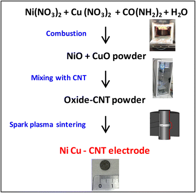
The developed methodology is sketched in Fig. 1 (detailed in the ESI† and Fig. S1): (i) combustion synthesis of a powder made up of an intimate mixture of NiO and CuO, (ii) ball-milling, mixing with CNTs and lyophilization, and (iii) consolidation by SPS with in situ formation of the metallic Ni–Cu nanoparticles.
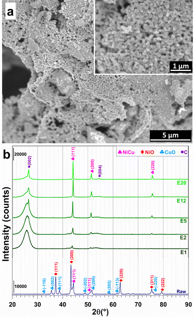
The raw powder was prepared by the nitrate-urea combustion route,26,27 in a furnace preheated at 700 °C for 15 min, using 5 times the so-called stoichiometric fuel (urea) proportion. Scanning electron microscopy (SEM) images (Fig. 2a) reveal the presence of primary grains 50–200 nm in size forming large agglomerates. The X-ray diffraction (XRD) pattern (pattern “raw” in Fig. 2b) reveals the peak characteristics of NiO, CuO and some Ni–Cu alloy, in line with the aforementioned reducing (fuel-rich) conditions. Less than 1 wt% of residual carbon was found by CHNS analysis. Energy-dispersive X-ray spectroscopy (EDS) confirms the expected Ni/Cu and O/(Ni + Cu) atomic ratios of 3.7 ± 0.5 and 0.7 ± 0.2 (Fig. S2, ESI†). The raw powder was ball-milled in order to break the agglomerates and was divided in several batches, which were mixed with the CNTs [Nanocyl, Belgium (specific surface area: 242 m2 g−1; average number of CNT walls: 8; average CNT external diameter: 10 nm; maximum CNT length: 1.5 μm)27], using sonication in water, before lyophilization. Five (5) metal oxide-CNT powders were prepared (1.2, 2.4, 6, 15, and 25 wt% metal oxide).
 | ||
| Fig. 2 (a) SEM image of the raw powder (inset is a higher-magnification image). (b) XRD patterns of the raw powder and the electrodes prepared by SPS. | ||
The above powders underwent a SPS run in a vacuum (residual cell pressure < 12 Pa): (i) heating at 300 °C min−1 from room temperature to 600 °C (1 min dwell) with a charge of 100 MPa on the pellet, and (ii) heating at 100 °C min−1 to 1300 °C (3 min dwell). These conditions were found to be appropriate for CNT monoliths.20,25 The final cylindrical pellets (Fig. 1, bottom image) are 8 mm in diameter and 1.25 ± 0.25 mm thick. They will be referred to as E1, E2, E5, E12 and E20 (Eo, o = metal proportion in wt%) in the following.
The XRD patterns of the electrodes (Fig. 2b) display the characteristic (002) and (004) diffraction peaks of multi-walled CNTs at 25.5°–26.5° and 54.5°, respectively.28 XRD patterns reveal the (111), (200) and (220) peaks of a face-centred cubic Ni–Cu alloy.9–12 This result shows that the combination of high temperature and the reductive conditions in the SPS cell are sufficient to trigger the reduction of NiO and CuO into the metallic state. The formation of alloy particles (with probably some composition distribution, which may warrant further studies), as opposed to separate Ni and Cu particles, confirms that the raw oxide powder was an intimate mixture of NiO and CuO. A further analysis of the XRD patterns reveals a shift of the Ni–Cu diffraction peaks to higher values with increasing metal content, which suggests a strong metal–carbon interaction, which is known to positively contribute to the electrocatalytic activity and stability by modulating the adsorption of reactants and intermediates.29–32 The relative density of the electrodes is (63 ± 1)%, in good agreement with the values found for CNT monoliths (56–60%).24 The corresponding volumetric metal loadings are 13.5, 30.8, 63.3, 204.6, and 324.6 mg cm−3. Hence, this wide range of metal contents will allow the rationalization of the study of textural and electrocatalytic properties.
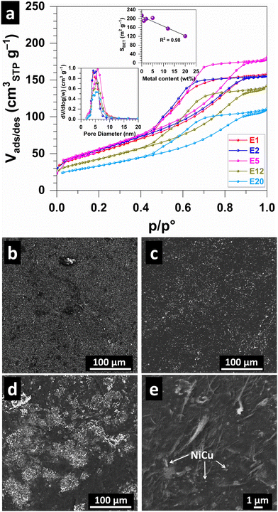
Fig. 3a shows the N2 adsorption–desorption isotherms, which are characteristic of the type IV(a) isotherm found for mesoporous materials.33 The pore size distribution (Fig. 3a and Table S1, ESI†) shows a peak at 4–5 nm. The calculated (BET specific surface area SBET (Fig. 3a and Table S1, ESI†) is 190, 198, 203, 155 and 121 m2 g−1 for E1, E2, E5, E12 and E20, respectively, compared to 214 m2 g−1 for the metal-free CNT monolith,24 reflects the increase in metal content in the sample. This could indicate that the consolidation of the CNT scaffold was unaffected by the presence of the Ni–Cu alloy nanoparticles. The specific pore volume [Barrett–Joyner–Halenda (BJH) method using the desorption branch of the isotherm] follows a similar decreasing trend, i.e., 0.234, 0.232, 0.265, 0.217, 0.178 cm3 g−1 for E1, E2, E5, E12 and E20, respectively. We next sought to study the surface of the electrodes. SEM images for E1 (Fig. 3b), E5 (Fig. 3c and Fig. S3, ESI†) electrodes show a homogeneous distribution of Ni–Cu particles (white on the images) while agglomerates are observed in E12 (Fig. 3d), which may suggest overloading for higher metal contents. A higher-magnification image (Fig. 3e) shows Ni–Cu particles dispersed in the porous CNT network.
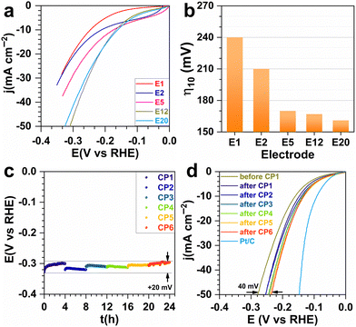
Having validated the ability to synthesize a library of electrodes with different characteristics, we then sought to study their catalytic activity for the HER. For each investigated metal content, several electrodes were prepared to verify the reproducibility of our results. Fig. 4a and b show the catalytic tests when the current was normalized by the estimated geometric surface area for each metal proportion (in wt%). The decrease in overpotential with increasing metal content reflects an improvement in electron transfer capability. The trend for the specific mass current density (Fig. S4, ESI†) could be attributed to the Ni–Cu particle agglomeration as well as to the decrease of the porous volume. They affect the availability of active sites and the evacuation of H2 bubbles, which can form a physical barrier between the electrolyte and the active sites.34 The Tafel slope of 232–313 mV dec−1 (Fig. S5, ESI†) indicates the electron transfer limitation by the Volmer reaction (H2O(l) + e− → H(ads) + HO−(aq)) with mass transfer interference.35 Based on these promising tests, the most efficient electrode (E5) was aged in order to study the durability. Chronopotentiometry at the metric current density of −0.1 A cm−2 was done for 24 h. The overpotential at −50 mA cm−2 went from 280 to 235 mV showing an even better performance after the ageing, probably because of better metal–carbon interaction.31,32 This result is comparable to the Ni–Cu based catalysts and is very promising (Table S2, ESI†).10–12,16
In conclusion, we have demonstrated for the first time that spark plasma sintering (SPS) can be used to reduce NiO and CuO to Ni75Cu25 nanoparticles while consolidating carbon nanotubes into a scaffold supporting them. The so-obtained electrodes show an appreciable catalytic activity for the hydrogen evolution reaction (HER). We highlight the tuneable properties (specific surface area from 208 to 121 m2 g−1, pore volume from 0.255 to 0.178 cm3 g−1, total metal content from 1 to 20 wt%) and electrocatalytic performance towards the HER in 1 M NaOH. The electrode operated at −0.1 A cm−2 (current of −0.15 A) for 24 h which resulted in an improved overpotential of about 235 mV.
This work was supported by Institut Carnot Chimie Balard Cirimat PhD Grant's program (J.-F.B.) and Région Occitanie/FEDER REACT H2VERT-NEPH program (C.E. and S.A.). The authors thank G. Chevallier (CIRIMAT and National CNRS SPS Platform) and M.-C. Barthélémy (CIRIMAT) for their help with SPS and N2 adsorption–desorption, respectively.
Conflicts of interest
There are no conflicts to declare.Notes and references
- J. M. Ogden, Phys. Today, 2002, 55, 69–75 CrossRef CAS.
- B. G. Pollet, S. S. Kocha and I. Staffell, Curr. Opin. Electrochim, 2019, 16, 90–95 CrossRef CAS.
- M. Chatenet, B. G. Pollet, D. R. Dekel, F. Dionigi, J. Deseure, P. Millet, R. D. Braatz, M. Z. Bazant, M. Eikerling and I. Staffell, Chem. Soc. Rev., 2022, 51, 4583–4762 RSC.
- V. Zgonnik, Earth-Sci. Rev., 2020, 203, 103140 CrossRef CAS.
- E. Hand, Science, 2023, 379, 630–636 CrossRef PubMed.
- V. R. Stamenkovic, D. Strmcnik, P. P. Lopes and N. M. Markovic, Nat. Mater., 2017, 16, 57–69 CrossRef CAS PubMed.
- W. Kreuter and H. Hofmann, Int. J. Hydrogen Energy, 1998, 23, 661–666 CrossRef CAS.
- K. Zeng and D. Zhang, Prog. Energy Combust. Sci., 2010, 36, 307–326 CrossRef CAS.
- M. A. Ahsan, A. R. Puente Santiago, Y. Hong, N. Zhang, M. Cano, E. Rodriguez-Castellon, L. Echegoyen, S. T. Sreenivasan and J. C. Noveron, J. Am. Chem. Soc., 2020, 142, 14688–14701 CrossRef CAS PubMed.
- C. Wei, Y. Sun, G. G. Scherer, A. C. Fisher, M. Sherburne, J. W. Ager and Z. J. Xu, J. Am. Chem. Soc., 2020, 142, 7765–7775 CrossRef CAS PubMed.
- Y. Shen, Y. Zhou, D. Wang, X. Wu, J. Li and J. Xi, Adv. Energy Mater., 2018, 8, 1701759 CrossRef.
- B. Liu, H.-Q. Peng, J. Cheng, K. Zhang, D. Chen, D. Shen, S. Wu, T. Jiao, X. Kong, Q. Gao, S. Bu, C.-S. Lee and W. Zhang, Small, 2019, 15, 1901545 CrossRef CAS PubMed.
- P. Farinazzo Bergamo Dias Martins, P. Papa Lopes, E. A. Ticianelli, V. R. Stamenkovic, N. M. Markovic and D. Strmcnik, Electrochem. Commun., 2019, 100, 30–33 CrossRef.
- B. G. Pollet and S. S. Kocha, Johnson Matthey Technol. Rev., 2022, 66, 61–76 CrossRef CAS.
- W. Zhu, X. Yue, W. Zhang, S. Yu, Y. Zhang, J. Wang and J. Wang, Chem. Commun., 2016, 52, 1486–1489 RSC.
- X. Zhang, J. Wang, J. Wang, J. Wang, C. Wang and C. Lu, J. Phys. Chem. Lett., 2021, 12, 11135–11142 CrossRef CAS PubMed.
- Y. Holade, Z. H. Kavousi, M. Ghorbanloo, N. Masquelez, S. Tingry and D. Cornu, Chem. Commun., 2023, 59, 47–50 RSC.
- Z. Li, S. Xin, Y. Zhang, Z. Zhang, C. Li, C. Li, R. Bao, J. Yi, M. Xu and J. Wang, Chem. Eng. J., 2023, 451, 138540 CrossRef CAS.
- Z. Zhang, L. Deng, Z. Zhao, Y. Zhao, J. Yang, J. Jiang, G. Huang and Y. Mei, J. Mater. Chem. A, 2020, 8, 3499–3508 RSC.
- S. D. De la Torre, D. Oleszak, A. Kakitsuji, K. Miyamoto, H. Miyamoto, R. Martínez-S, F. Almeraya-C, A. Martínez-V and D. Rios-J, Mater. Sci. Eng. A, 2000, 276, 226–235 CrossRef.
- P. Ma, M. Zhao, L. Zhang, H. Wang, J. Gu, Y. Sun, W. Ji and Z. Fu, J. Materiomics, 2020, 6, 736–742 CrossRef.
- S. J. Sitler, K. S. Raja and I. Charit, J. Electrochem. Soc., 2016, 163, H1069 CrossRef CAS.
- B. Daffos, G. Chevallier, C. Estournès and P. Simon, J. Power Sources, 2011, 196, 1620–1625 CrossRef CAS.
- C. Laurent, T. M. Dinh, M. C. Barthélémy, G. Chevallier and A. Weibel, J. Mater. Sci., 2018, 53, 3225–3238 CrossRef CAS.
- J. Gurt Santanach, C. Estournès, A. Weibel, A. Peigney, G. Chevallier and C. Laurent, Scr. Mater., 2009, 60, 195–198 CrossRef.
- K. C. Patil, Bull. Mater. Sci., 1993, 16, 533–541 CrossRef CAS.
- P. Coquay, E. De Grave, A. Peigney, R. E. Vandenberghe and C. Laurent, J. Phys. Chem. B, 2002, 106, 13186–13198 CrossRef CAS.
- J. Cambedouzou, M. Chorro, R. Almairac, L. Noé, E. Flahaut, S. Rols, M. Monthioux and P. Launois, Phys. Rev. B: Condens. Matter Mater. Phys., 2009, 79, 195423 CrossRef.
- H. P. Tran, H. N. Nong, H.-S. Oh, M. Klingenhof, M. Kroschel, B. Paul, J. Hübner, D. Teschner and P. Strasser, Chem. Mater., 2022, 34, 9350–9363 CrossRef CAS.
- J. Ma, A. Habrioux, C. Morais, A. Lewera, W. Vogel, Y. Verde-Gómez, G. Ramos-Sanchez, P. B. Balbuena and N. Alonso-Vante, ACS Catal., 2013, 3, 1940–1950 CrossRef CAS.
- Y. Liu, Q. Feng, W. Liu, Q. Li, Y. Wang, B. Liu, L. Zheng, W. Wang, L. Huang, L. Chen, X. Xiong and Y. Lei, Nano Energy, 2021, 81, 105641 CrossRef CAS.
- C. Lei, W. Zhou, Q. Feng, Y. Lei, Y. Zhang, Y. Chen and J. Qin, Nano-Micro Lett., 2019, 11, 45 CrossRef CAS PubMed.
- M. Thommes, K. Kaneko, A. V. Neimark, J. P. Olivier, F. Rodriguez-Reinoso, J. Rouquerol and K. S. W. Sing, Pure Appl. Chem., 2015, 87, 1051–1069 CrossRef CAS.
- L. Wang, X. Huang, S. Jiang, M. Li, K. Zhang, Y. Yan, H. Zhang and J. M. Xue, ACS Appl. Mater. Interfaces, 2017, 9, 40281–40289 CrossRef CAS PubMed.
- M. Chatenet, J. Benziger, M. Inaba, S. Kjelstrup, T. Zawodzinski and R. Raccichini, J. Power Sources, 2020, 451, 227635 CrossRef CAS.
Footnote |
| † Electronic supplementary information (ESI) available: Experimental details; extended characterization. See DOI: https://doi.org/10.1039/d3cc04472f |
| This journal is © The Royal Society of Chemistry 2023 |


